
 English
 中文简体
中文简体 English
 Русский
 Español
 Português
 Türkçe
 العربية
 Deutsch
 Polski
 Italiano
 Français
 한국어
한국어 ไทย
ไทย Tiếng Việt
 日本語
日本語





























Low Temperature Tensile Testing
User's Manual
Applicable LISUN models: LS-B40
1. Basic Understanding of Equipment
1.1 Key Parameters
1.1.1 Equipment Technical Specifications
| Parameters | Note |
| Displacement Measurement | Digital display, resolution 0.1 mm |
| Chuck Types | Non-self-tightening |
| Tensile Speed | 25 ± 5 mm/min |
| Specimen Specifications | No. I and No. II Dumbbell Plates |
1.1.2 Applicable Standards
The LS-B40 Low Temperature Tensile Testing Machine strictly complies with GB/T 2951.14-2008″General Test Methods for Insulation and Sheathing Materials of Cables and Optical Fiber Cables—Part 14: General Test Methods—Low-Temperature Tensile Test” (IEC 60811-505:2012), specifically clauses 8.3 and 8.4.
It is primarily used in electrical product quality inspection laboratories, the quality control departments of manufacturers of flexible cables and electrical accessories, third-party testing organizations, and for import and export product inspections.
1.2 Equipment Configuration Verification
1.2.1 Unpacking
When unpacking the device, handle it gently to avoid scratching the outer casing with sharp tools. After unpacking, first inspect the exterior of the device to ensure there is no obvious deformation or dents, and that the buttons are not damaged or loose. If you notice any abnormalities with the device or its accessories, do not turn it on. Please contact us immediately.
1.2.2 Main Unit and Accessories
| Number | Note |
| ① | LS-B40 Main Unit |
| ② | Power Cord |
1.2.3 Downloading Electronic Documents
We have already sent the download links for the electronic user manual, calibration certificate, warranty card, and other documents via email at the time of shipment. Please download them promptly. If you have not received the email, please contact us to request the download links again.
2. Safety Precautions
2.1 Electrical Safety
Before connecting the power cord, verify that the supply voltage is AC 220 V ±10% and the frequency is 50 Hz or 60 Hz. You must use a three-prong outlet with a protective ground, and the protective ground resistance must be ≤4 Ω. Do not cut or disconnect the protective ground wire under any circumstances, as doing so poses a risk of electric shock.
2.2 Operating Procedures
During the test loading process, do not reach with your hands or body into the area of the clamps or the tensile transmission mechanism to prevent injuries from pinching or falling objects; the test specimen must be securely clamped to prevent it from falling out during the test; setting non-standard test speeds is strictly prohibited; and disassembling the machine without authorization is strictly prohibited.
3. Equipment Overview
3.1 Physical Composition of the Equipment
See Figure 3-1.
| Number | Note |
| ① | Power Switch |
| ② | Touchscreen |
| ③ | Buzzer alarm: The buzzer sounds when the movable chuck reaches the limit position. |
| ④ | Motor |
| ⑤ | Specimen chucks (two in total); the one on the left is the fixed chuck, and the one on the right is the movable chuck. |
| ⑥ | Limit switches—two in total (one on the left and one on the right) |
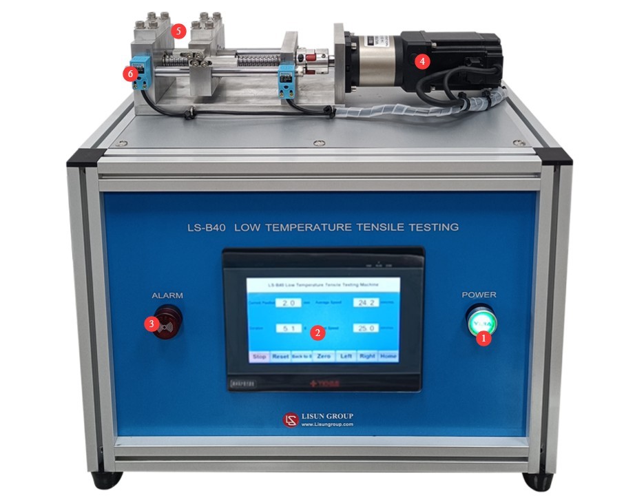
Figure 3-1
3.2 Touchscreen Program Interface
3.2.1 Initial Screen
See Figure 3-2.
| Number | Note |
| ① | Go to the Test Interface |
| ② | Go to the Help screen |

Figure 3-2
3.2.2 Test Interface
See Figure 3-3.
| Number | Note |
| ① | Current Displacement |
| ② | Average displacement velocity for this test |
| ③ | Current Test Duration |
| ④ | Set the test speed; the default setting is 25 mm/min (see Section 1.1.2 for applicable standards). Note: Setting a non-standard test speed is strictly prohibited. If you have other requirements, please confirm them with us first. |
| ⑤ | Start/Stop Test |
| ⑥ | Reset: Clears test data (including current displacement, average displacement speed for the current test, and current test duration) and clears the buzzer alarm. |
| ⑦ | Click to return the movable chuck to the 0 position |
| ⑧ | Click to set the current moving chuck position to position 0 |
| ⑨⑩ | Click to move the movable chuck to the left or right |
| ⑪ | Return to the Home Screen |
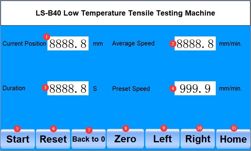
Figure 3-3
4. Low-Temperature Tensile Test
4.1 Sample Preparation
Two test specimens of appropriate length shall be taken from each test conductor and test jacket. The test specimens shall have a thickness of not less than 0.8 mm and not more than 2 mm. They shall then be stored at an ambient temperature of 23 °C ± 5 °C for at least 16 hours, after which two dumbbell-shaped test pieces, as shown in Figures 1 and 2 (if necessary) of Figure 4-1, shall be punched out along the axial direction of the test specimen.
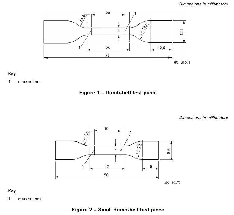
Figure 4-1
4.2 Pre-cooling Treatment
As shown in Figure 4-2, remove the device’s chuck assembly and place it in the low-temperature test chamber together with the test specimen to pre-cool for 4 hours.
Figure 4-2
Next, place the Low Temperature Tensile Testing machine inside the low-temperature test chamber and reinstall the pre-cooled jaws onto the machine.
Note: The specific low-temperature test temperature should be determined by referring to the requirements for low-temperature performance in the relevant standards for different types of cables.
4.3 Sample Installation and Commissioning
Turn on the device. Based on the dimensions of the test specimen, click “Move Left” or “Move Right” to move the movable chuck, then secure both ends of the test specimen to the two chucks, and click to set the current position of the movable chuck to the zero position.
4.4 Start-up Test
Set the test speed preset to 25 mm/min. Then click “Start Test.”
If the specimen breaks during the tensile test, click “Stop Test” as soon as the break occurs. The touchscreen interface displays the current displacement, which is the tensile distance.
If the test specimen does not break at any point during the tensile test, the machine will sound an alarm when the jaws reach the stop. This indicates that the test specimen meets the standard requirements; click the “Reset” button to clear the buzzer alarm.
4.5 Evaluation of Test Results
Calculate the elongation according to the standard. Unless otherwise specified, valid test results must not be less than 20 percent.
4.6 Post-Test Procedures
4.6.1 Device Reset
After the test is complete, remove the main unit from the low-temperature test chamber; do not leave the main unit inside the low-temperature test chamber for extended periods of time.
4.6.2 Sample Preparation
Separate the samples that passed and failed the test, label them clearly, and avoid confusion.
5. Daily Maintenance and Care of Equipment
5.1 Daily Maintenance After Shutdown
At the end of each day’s testing, clean dust and sample debris from the equipment surfaces, and keep the chucks and slide rails clean and free of debris; use a dedicated screen-cleaning cloth to clean the touchscreen; check that the chucks are not loose or deformed.
5.2 Weekly Routine Maintenance
Apply a small amount of special-purpose lubricating grease to the equipment’s guide rails and drive screws to ensure smooth, jam-free operation.
5.3 Maintenance During Long-Term Storage
After powering down the equipment for cleaning and completing routine maintenance, cover the entire unit with a dust cover and store it in a dry, well-ventilated warehouse; power it on for 30 minutes each month to prevent components from becoming damaged due to moisture.
5.4 Calibration Interval Requirements
To ensure the measurement accuracy and operational reliability of the equipment, it is recommended that it be sent periodically to a qualified third-party metrology laboratory for calibration. The recommended calibration interval is 12 months. The specific calibration interval may be determined by the user based on frequency of use, environmental conditions, and quality system requirements.
6. Troubleshooting and Resolving Common Problems
| Fault Symptoms | Possible Causes | Procedure |
| Touchscreen lags; taps don’t register | Screen surface smudges causing interference; program crashes | Turn off the device, clean the screen, then restart it and try again. |