
 English
 中文简体
中文简体 English
 Русский
 Español
 Português
 Türkçe
 العربية
 Deutsch
 Polski
 Italiano
 Français
 한국어
한국어 ไทย
ไทย Tiếng Việt
 日本語
日本語





























Solid Insulation Electric Strength Test Device
User's Manual
Applicable LISUN models: LS-B25
1. Basic Understanding of Equipment
1.1 Scope Of Application Of the Equipment
Suitable for testing the dielectric strength, breakdown voltage, and voltage withstand performance of sheet-like, block-like, and plate-like solid insulating specimens made of plastics, rubber, resins, insulating paperboard, composite solid insulating materials, and similar materials.
Widely used for compliance testing of solid insulating materials in industries such as electronics and electrical appliances, electrical insulation, new energy, building materials, scientific research laboratories, and quality inspection agencies.
1.2 Applicable Standards
Strictly complies with Figure 29 of Clause 5.4.9 of GB/T 4943.1-2022, Figure 29 of Clause 5.4.9 of IEC 62368-1:2023, andand the solid insulation withstand voltage test requirements specified in Section 40.2 of UL 1310-2022, fully conforming to the standards’ requirements for electrode configuration, specimen clamping, and test conditions.
2. Safety Precautions
2.1 Operating Environment Safety Requirements
The test apparatus must be placed on a stable, level surface and kept out of direct sunlight;
The test site must be kept dry and free of flammable or explosive materials, and the environment must be free of conductive dust and corrosive gases;
Keep away from equipment that emits strong electromagnetic interference.
2.2 Safety Guidelines for the Testing Process
Operators must wear rubber insulated gloves, and warning signs must be posted in high-voltage areas;
Operators must have dry hands and must not wear any metal jewelry; eating or drinking is prohibited during testing to prevent accidents caused by electric shock;
Do not touch the electrodes or the test specimen under any circumstances during the test;
Before replacing the test specimen, you must first stop the test;
When multiple people are involved, clearly define roles and responsibilities, and confirm them with each other before starting the test to avoid errors.
3. Equipment Overview
3.1 Standard Diagram
See Figure 3-1 (taken from the IEC standard).
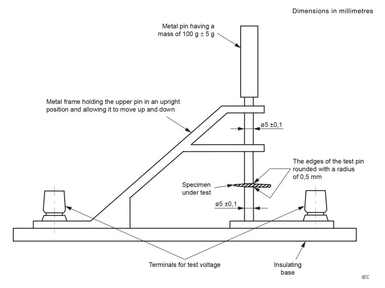
Figure 3-1
3.2 Product Photos
See Figure 3-2.
| Number | Note |
| ① | 100g metal rod electrode, compliant with GB and IEC standards |
| ② | 50g metal rod electrode, compliant with UL standards |
| ③④ | The point where the upper and lower electrodes meet is where the specimen is mounted. Lift the metal rod electrode to place the specimen, then slowly lower the electrode into position. |
| ⑤⑥ | Test Voltage Terminals |
| ⑦ | Insulated Base |
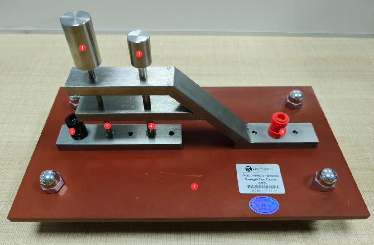
Figure 3-2
4. Dielectric Strength Test for Solid Insulation
4.1 Sample Preparation and Treatment
Cut into neat square or round pieces in accordance with the standard requirements; the pieces should be of uniform thickness and free of burrs, cracks, or dents.
Wipe the top and bottom surfaces of the specimen with anhydrous ethanol to remove dust, grease, and impurities, then allow it to air dry for 5 minutes.
4.2 Setting of Test Parameters
Verify the test criteria and conduct the test in accordance with the specified test voltage, voltage-rise rate, voltage-holding time, overcurrent protection, and other requirements.
4.3 Breakdown Criteria
If the test specimen exhibits perforations, carbonization, spalling, or sustained arcing, it is deemed to have failed the insulation breakdown test.
Non-destructive, transient, and minor flashovers are exempted in accordance with the standard; sustained creepage and arc flashovers are deemed to fail the flashover test.
If there is no breakdown, no sustained flashover, and no physical damage, the dielectric strength is deemed to meet the requirements.
5. Post-Test Procedures
5.1 Removal and Storage of Test Specimens
After the test, the electrodes will retain residual heat; wait 2–3 minutes for them to cool before removing the test specimen.
Gently lift the metal rod electrode, remove the sample, and place it in a dry storage container for safekeeping.
Non-conforming specimens must be stored separately and labeled with the test number, test date, and type of non-conformity; they must not be stored together with conforming specimens under any circumstances.
5.2 Organizing the Test Site
Wipe down the test apparatus and electrode surfaces with a lint-free cloth to remove sample debris and dust.
Return the specimen-cutting tools, cleaning reagents, and auxiliary fixtures to their designated locations.
After confirming that the equipment is completely de-energized and there are no high-voltage hazards, remove the test isolation warning signs.
6. Daily Maintenance and Care of Equipment (Electrodes)
6.1 Weekly Routine Maintenance
Inspect the surface of the standard electrode for scratches, oxidation, or deformation. If there is minor oxidation, gently polish it with special metal polishing cotton, then wipe it clean with anhydrous ethanol.
6.2 Rust Protection for Electrodes
After cleaning, place the item in a dry, airtight storage container with a desiccant and store it in a dry, dark place to prevent moisture and oxidation.
6.3 Electrode Replacement and Maintenance
If the electrode surface is worn, deformed, or no longer ensures a concentric fit, it must be replaced with a genuine, standard electrode replacement part.