
 English
 中文简体
中文简体 English
 Русский
 Español
 Português
 Türkçe
 العربية
 Deutsch
 Polski
 Italiano
 Français
 한국어
한국어 ไทย
ไทย Tiếng Việt
 日本語
日本語





























HBM/MM ESD Simulator
User's Manual
Applicable LISUN models: ESD-883D、ESD-883D/ESD-CDM
1. Important Notes
This instrument is a precision high-voltage device. To ensure the safety of users and extend the instrument’s service life, please observe the following precautions when using it:
Please use this instrument in an environment with a relative humidity of 10% to 70%;
The instrument’s F. G. terminal must be properly grounded;
After the instrument is powered on, do not touch the discharge electrode with your hands to avoid electric shock;
When plugging in or unplugging high-voltage connectors or switching test modules, ensure that the instrument is in the STOP state to prevent electric shock;
When replacing the resistor-capacitor kit, do not push or pull it forcefully to avoid damaging it;
Before turning off the power to the main unit, make sure the instrument is in the “STOP” state.
Laboratory Test Conditions:
In air discharge mode, climatic conditions should fall within the following ranges:
Ambient temperature: 15°C to 35°C
Relative humidity: 30%–60%
Atmospheric pressure: 68–106 kPa
In addition, the electromagnetic environment in the laboratory should not affect the test results.
Direct discharge onto the test equipment:
The test shall be conducted on points and surfaces of the equipment under test that an operator might touch during normal operation. The test voltage shall be gradually increased from a low level to a high level, ultimately reaching the selected severity level.
2. Equipment Overview
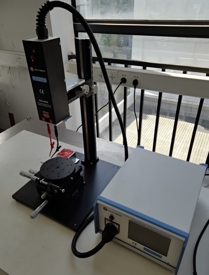
The ESD-883D Semiconductor Electrostatic Discharge Simulator (hereinafter referred to as the ESD-883D), also known as a semiconductor electrostatic discharge immunity tester, can simulate electrostatic discharge caused by a charged human body or device to test the ESD performance of electronic components.
This instrument complies with the ANSI/ESD STM5.1, ANSI/ESD STM5.2, EIA/JESD22-A114-B, and EIA/JESD22-A115-A standards. Its output electrostatic voltage range is 100 V to 8 kV, covering all electrostatic test levels required by the standards.
The instrument has two operating modes: Human Body Model (HBM) and Machine Model (MM). The discharge count range is 1 to 999, which is sufficient to meet the electrostatic discharge testing requirements for most electrical and electronic devices.
1. Description of Front Panel Functions
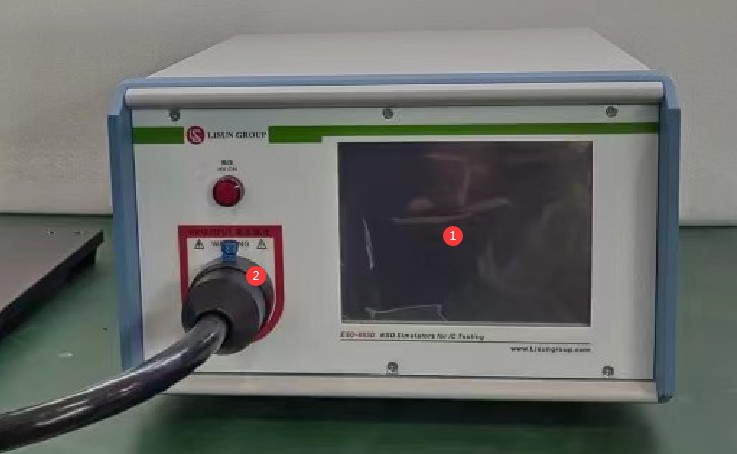
Schematic Diagram of the Front Panel of the ESD-883D Electrostatic Discharge Immunity Tester
= 1 * GB3① Touchscreen LCD for setting and controlling discharge parameters.
= 2 * GB3② High-Voltage Socket: The discharge gun’s high-voltage cable and control wires are connected to the main unit via the high-voltage socket. The high-voltage socket assembly must be properly connected before turning on the instrument’s power. When inserting the high-voltage plug into the high-voltage socket, align it with the socket’s positioning pins, then gently insert it all the way and tighten the retaining cap. Note: Forcibly inserting the plug without aligning it with the positioning pin will damage the fine copper pins inside the high-voltage plug.
2. Description of the Functions of the Instrument’s Front and Rear Panels
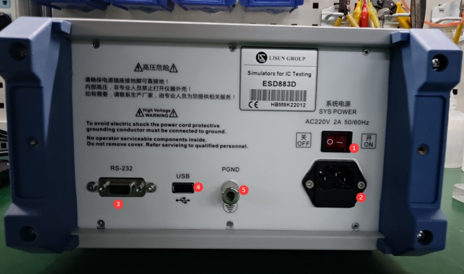
Schematic Diagram of the Rear Panel of the ESD-883D Electrostatic Discharge Immunity Tester
= 1 * GB3① Instrument power switch.
= 2 * GB3② Instrument power outlet, with built-in fuse.
= 3 * GB3③ RS232/RS485 communication ports, spare
= 4 * GB3④ USB ports for connecting USB flash drives, mice, and other devices.
= 5 * GB3⑤ Grounding Terminal. This port must be properly grounded when the device is powered on.
3. Discharge Tower
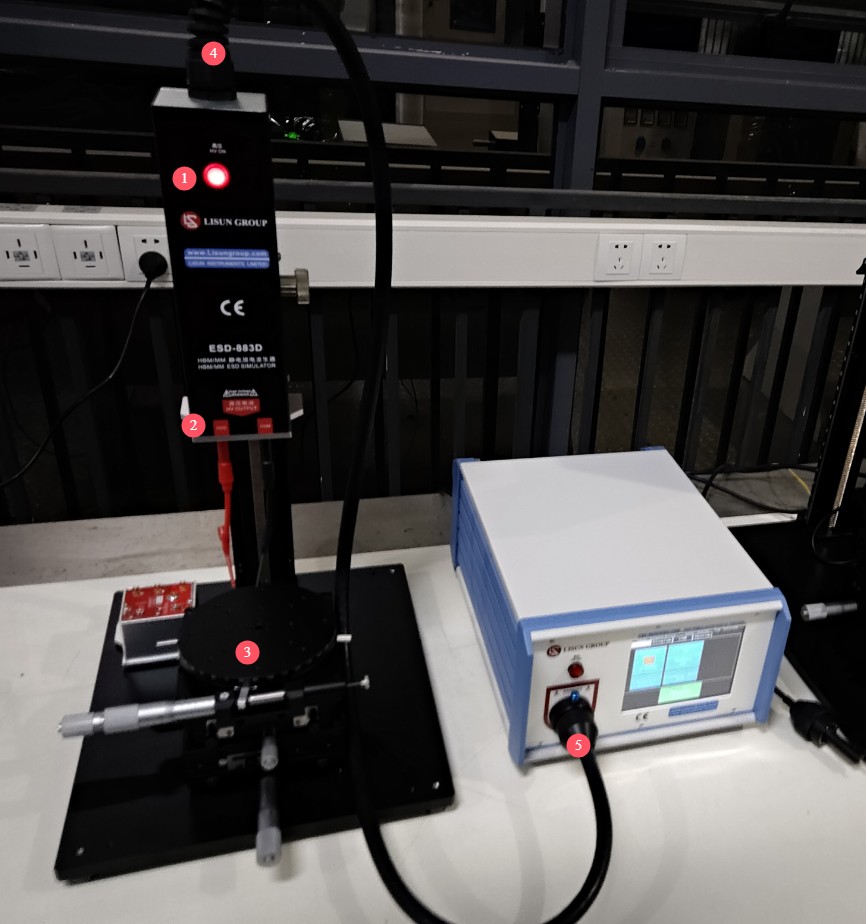
Discharge Tower
The functions of the various parts shown in the figure are as follows:
= 1 * GB3① High-Voltage Indicator: The high-voltage indicator is an operational indicator that lights up once the instrument’s high voltage is activated.
= 2 * GB3② High-Voltage Output Ports: During testing, simply connect the red and black ports to the test specimen.
= 3 * GB3③ Test Socket: During testing, the test item must be placed on the test socket and connected to the output port.
= 4 * GB3④ High-voltage composite cable: Connects the discharge gun to the main unit.
= 5 * GB3⑤ High-Voltage Connector: Used to secure the connection between the high-voltage composite cable and the main unit. Note: When inserting the high-voltage connector, align it precisely with the connector port, then gently push it into the port, and finally press down on the latch. Never force the connector into the port, as this may damage the pins. Do not pull or push the high-voltage cable with force; instead, hold the retaining cap when inserting or removing it.
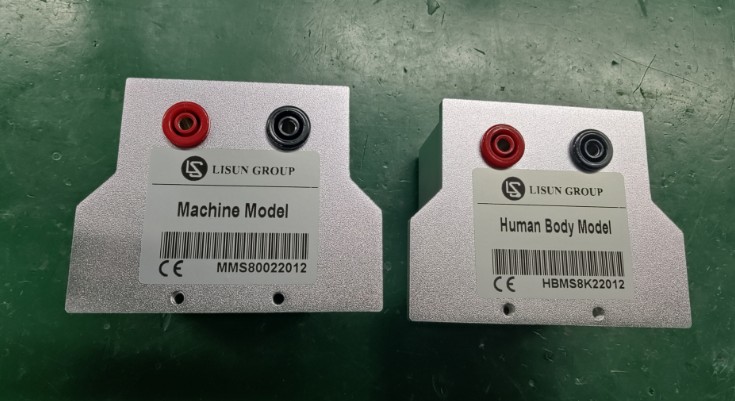
4. Human Body Model (HBM) and Machine Model (MM) RC kits:
3. Equipment Operation
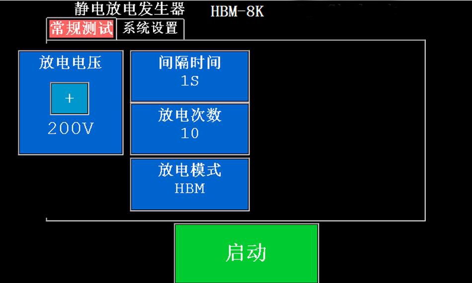
Schematic Diagram of the ESD-883D Electrostatic Discharge Parameter Settings Interface
1. Discharge Voltage Setting
Click the “Discharge Voltage” button on the parameter settings screen to open the voltage settings screen, as shown below:
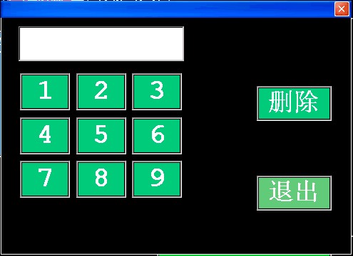
Discharge Voltage Settings Screen
On the settings screen, simply tap the number buttons to enter the desired discharge voltage; the voltage setting range is 100 V to 8 kV.
The “Delete” button is used to delete the digit or decimal point at the cursor’s position;
The “Confirm” button is used to confirm the value in the edit box; tapping it closes the numeric keypad window;
The “Exit” button closes the numeric keypad window, and the value in the text box is discarded.
2. Setting the Discharge Interval
Click the “Interval” button on the parameter settings screen to open the settings screen, as shown below:
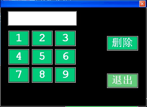
Interval Settings Screen
As shown in Figure 5, simply enter the desired discharge interval time; the discharge interval can be set within the range of 1 to 99 seconds;
The “Delete” button is used to delete the digit or decimal point at the cursor’s current position;
The “Confirm” button is used to confirm the value in the edit box; tapping it closes the numeric keypad window;
The “Exit” button closes the numeric keypad window, and the value in the text box is discarded.
3. Number of Discharge Cycles Setting
Click the “Discharge Count” button on the parameter settings screen to open the settings screen, as shown below:
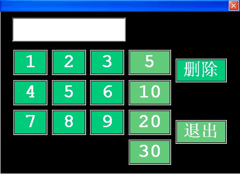
Discharge Count Settings Screen
Simply click the number buttons to enter the desired number of discharge cycles; the setting range is 1 to 999 cycles;
The “Delete” button is used to delete the digit or decimal point at the cursor’s current position;
The “Confirm” button is used to confirm the value in the edit box; tapping it closes the numeric keypad window;
The “Exit” button closes the numeric keypad window, and the value in the edit box is discarded.
4. Selection of Discharge Trigger Mode
The discharge mode does not require manual configuration; it is automatically detected based on the installed RC kit. Below are photos of the RC kit and a screenshot of the mode display on the instrument.
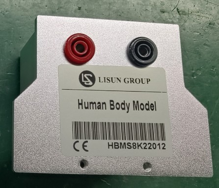
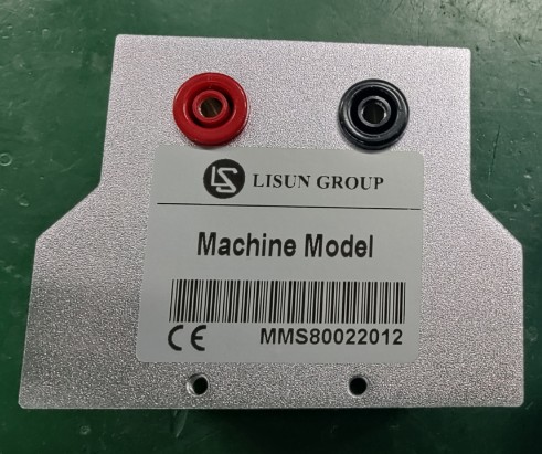
Human Body Model (HBM) Machine Model (MM)
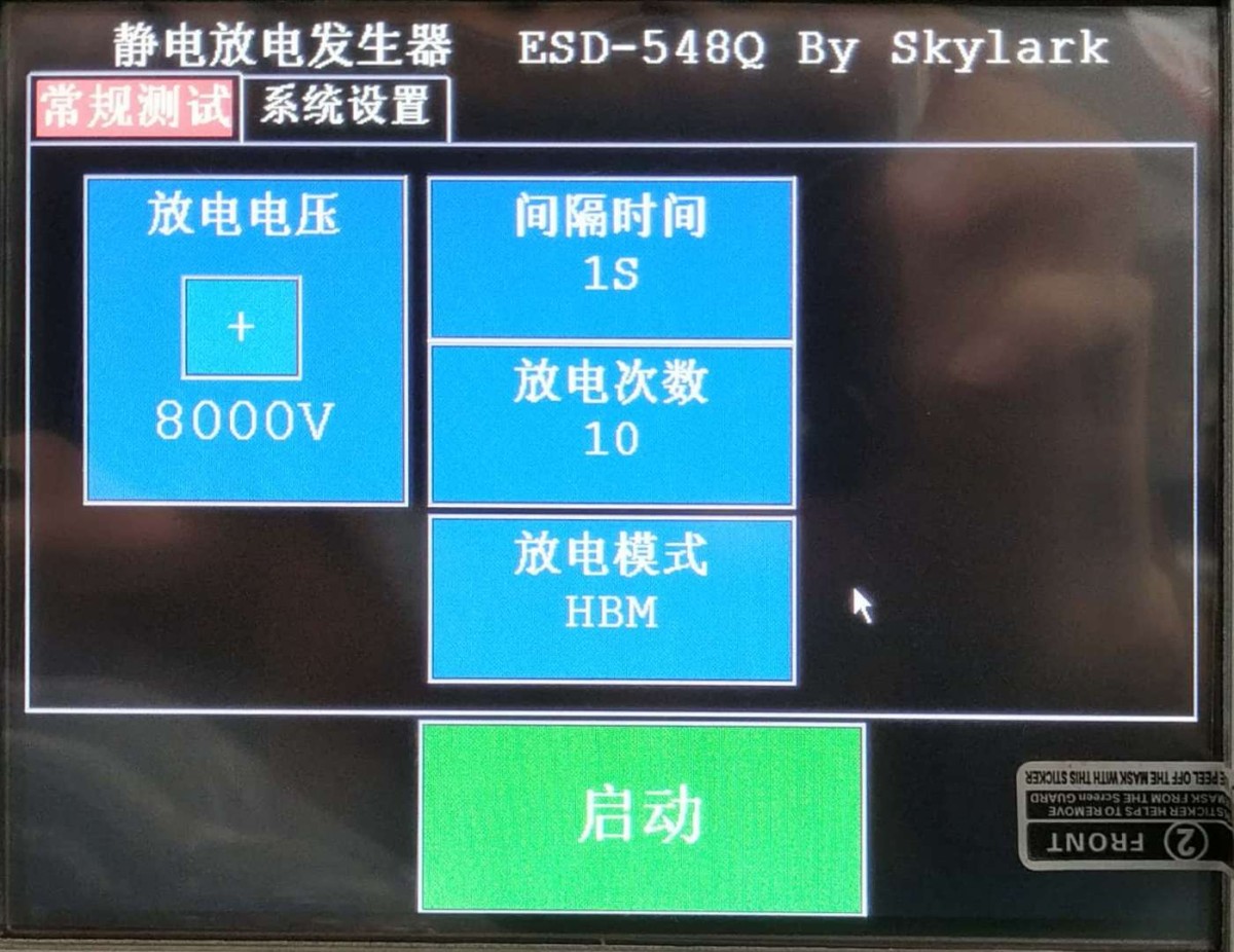
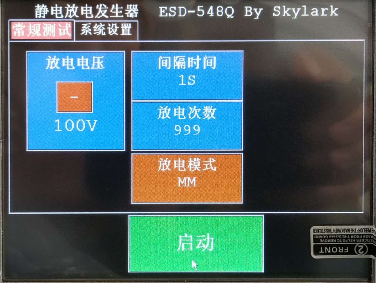
Human Body Model (HBM) Recognition Chart Machine Model (MM) Recognition Chart
5. Test Procedure
Plug in the discharge device;
Plug in the instrument’s power cord;
Turn on the power to the Electrostatic Discharge Simulator and wait for the instrument to start up and enter the operating interface;
Set the discharge voltage;
Set the discharge interval;
Set the number of discharge cycles;
View the discharge mode;
Tap the “Start” button to enter the discharge-ready state; at this point, the “Start” button changes to a “Stop” button;
Align the discharge device with the discharge site; once proper contact is established, press “Start Test” to begin the discharge test;
Each time a discharge occurs, the counter increments by 1 until the set number of discharges is reached, at which point the system exits the discharge and pending discharge states.
6. Evaluation of Experimental Results
Test results must be recorded separately based on the operating conditions and functional requirements of the equipment under test, so that both the equipment manufacturer and the user can evaluate the equipment. For example:
1. Under specified conditions, the equipment operates normally;
2. During the test, the equipment experiences a temporary decline in performance or loss of function, but subsequently recovers on its own;
3. Temporary performance degradation or loss of functionality in the equipment can only be resolved through operator intervention or a system reset;
4. Irreversible performance degradation or loss of functionality of the equipment due to damage to components, software issues, or data loss.
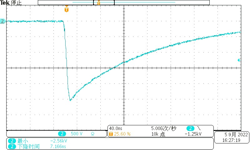
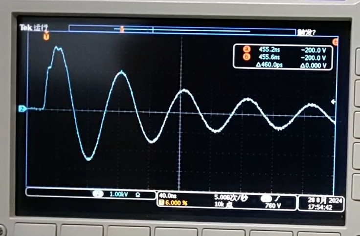
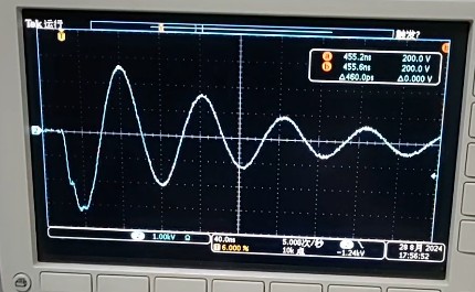
4. Equipment Discharge Waveform Diagram
HBM Module Discharge Waveform Diagram
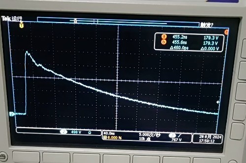
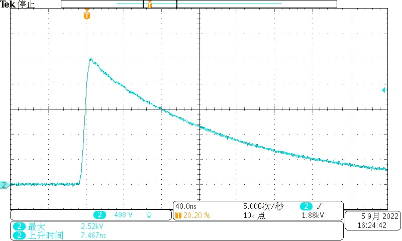
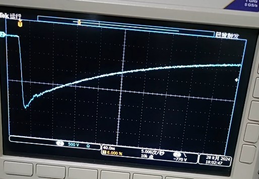
MM Module Discharge Waveform Diagram
5. Packing List
| 1 | ESD-883D Main Unit | 1 |
| 2 | Power Cord | 1 |
| 3 | High-Voltage Test Cables and Brackets | 1 |
| 4 | MM Modules and HBM Modules | 1 each |
| 5 | User Manual | 1 |
| 6 | Factory Calibration Certificate | 1 |
| 7 | Warranty Card | 1 |
Note: Items 5, 6, and 7 may be download links for the digital version.
LED Luminaires and LED Power Driver Test Solution
Goniophotometer System: LSG-6000, LSG-1890B, or LSG-1700
Spectroradiometer & Integrating Sphere Test System: LPCE-2 or LPCE-3
LED Life Maintains a Test System in Accordance with LM-80: LEDLM-80PL
Waterproof Test for IPX5 and IPX6 Testing: JL-56
Dustproof Testing Machine for IP5X and IP6X Testing: SC-015
LED Power Driver Testers: LS2090 (for the lab) and ATE-2 (for the production line)
Electrical Safety Tester: LS9955
CFL and Electronic Ballast Test Solution
Goniophotometer System: LSG-1890B or LSG-1700
Integrating Sphere and Spectrophotometer Test System: LPCE-2 or LPCE-3
Adjustable Reference Ballast: DYJ-50HZ, HCS-109A, and DYJ-HID
Electric Ballast Tester: WT5000 (for the lab) and ATE-1 (for the production line)
Digital Torsion Meter and Multiway Life Tester: CH338 and CH316
Electrical Safety Testers: LS9923, ZRS-3H, ZY-3
EMC and EMI Test Solutions for CFL and LED Luminaires
EMI Test System: EMI-9KB or EMI-9KA
Electrostatic Discharge Simulator: ESD61000-2
EFT Immunity Measurement: EFT61000-4
Surge Generator: SG61000-5
Voltage Dips and Interruptions Generator: CSS61000-11
Ring Wave Generator: RWG61000-12

www. Lisungroup.com
Patents Filed
All Rights Reserved by Lisun Group
Subject to Change Without Notice