
 English
 中文简体
中文简体 English
 Русский
 Español
 Português
 Türkçe
 العربية
 Deutsch
 Polski
 Italiano
 Français
 한국어
한국어 ไทย
ไทย Tiếng Việt
 日本語
日本語





























RoHS Testing Equipment
User's Manual
Applicable LISUN models: EDX-2A、EDX-2AB、EDX-2ABC、EDX-2AC、EDX-2T
1. Basic Understanding of Equipment
1.1 Key Parameters
1.1.1 Model Classification
| Specifications/Model Numbers | EDX-2A | EDX-2AC | EDX-2AB | EDX-2ABC | EDX-2T |
| Type | Non-vacuum desktop model | Benchtop Vacuum Pump | |||
| Sample Chamber Dimensions | 610 × 320 × 100 mm (L × W × H) | Atmospheric: 510 × 310 × 120 mm; Vacuum: Φ100 × 70 mm |
|||
| Test Environment | Atmosphere | Atmosphere, Vacuum | |||
| Types of Test Samples | Solids, liquids, powders | Atmospheric: solids, liquids, powders ; Vacuum: solids |
|||
| Test Items | RoHS | RoHS+ Coating Testing | RoHS+ Alloy Analysis | RoHS + Alloy Analysis + Plating Testing | |
| Test Range for Alloying Elements | N/A | Alloy analysis can be performed on all elements in the periodic table from sulfur (16-S) to uranium (92-U) (including iron, copper, stainless steel, gold, platinum, etc.). | Vacuum analysis can be performed on all elements in the periodic table, from 11-Na (sodium) to 92-U (uranium), for alloy analysis (magnesium-aluminum alloys, ore compositions, iron, copper, stainless steel, gold, platinum, etc.). | ||
Note: When using the EDX-2T, the vacuum function is required only for alloy analysis to obtain more accurate and comprehensive test results.
1.1.2 Introduction to RoHS
RoHS is a mandatory standard established by European Union legislation; its full name is Restriction of Hazardous Substances. Its purpose is to eliminate six substances—lead (Pb), mercury (Hg), cadmium (Cd), hexavalent chromium (CrVI), polybrominated biphenyls (PBBs), and polybrominated diphenyl ethers (PBDEs)—from electrical and electronic products. Specifically, for RoHS 1.0, the EDX-2 series can measure the content of chlorine (Cl), lead (Pb), mercury (Hg), cadmium (Cd), hexavalent chromium (CrVI), and bromine (Br).
Note: The standard testing method measures the total bromine (Br) content; if the total content does not exceed the limit, then neither polybrominated biphenyls (PBBs) nor polybrominated diphenyl ethers (PBDEs) will exceed the limit; If you need to distinguish between polybrominated biphenyls (PBBs) and polybrominated diphenyl ethers (PBDEs) and test the levels of both substances, additional equipment is required; please contact us.
The new directive adds four phthalates—di(2-ethylhexyl) phthalate (DEHP), butyl benzyl phthalate (BBP), dibutyl phthalate (DBP), and diisobutyl phthalate (DIBP). This is known as RoHS 2.0 (2011/65/EU), and testing must be performed using the LISUN EDX-4 device.
1.2 Equipment Configuration Verification
1.2.1 Unpacking
When unpacking the device, handle it gently to avoid scratching the outer casing with sharp tools. After unpacking, first inspect the exterior of the main unit to ensure there is no visible deformation or dents, and that the buttons are not damaged or loose. If you notice any abnormalities with the device or its accessories, do not power it on. Please contact us immediately. The system primarily consists of the following components, as shown in Figure 1-1.
| Number | Note |
| ① | EDX-2 Series Spectrometer Main Unit |
| ② | Printer |
| ③ | All-in-One PC |
| ④ | Vacuum pump (included only with the EDX-2T) |
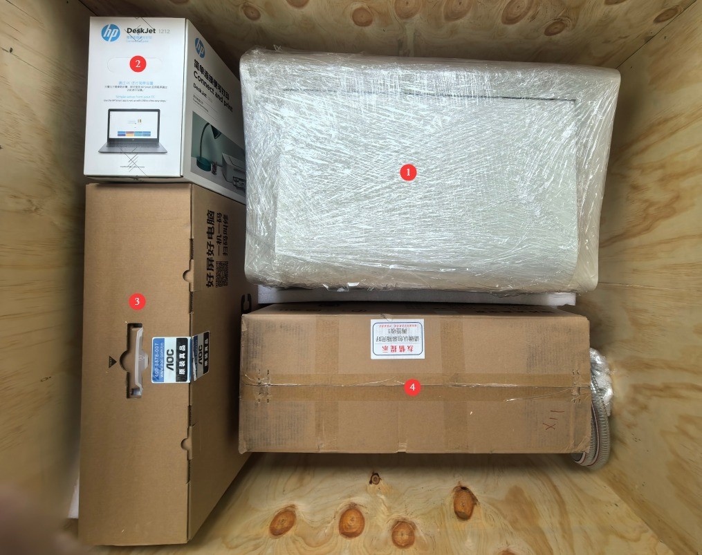
Figure 1-1
1.2.2 Other Major Components
See Figures 1-2. Open the main unit cover; the remaining major components were stored inside the test chamber during shipping. Please remove all components. Note: The arrow points to the vacuum chamber, which is included only with the EDX-2T.
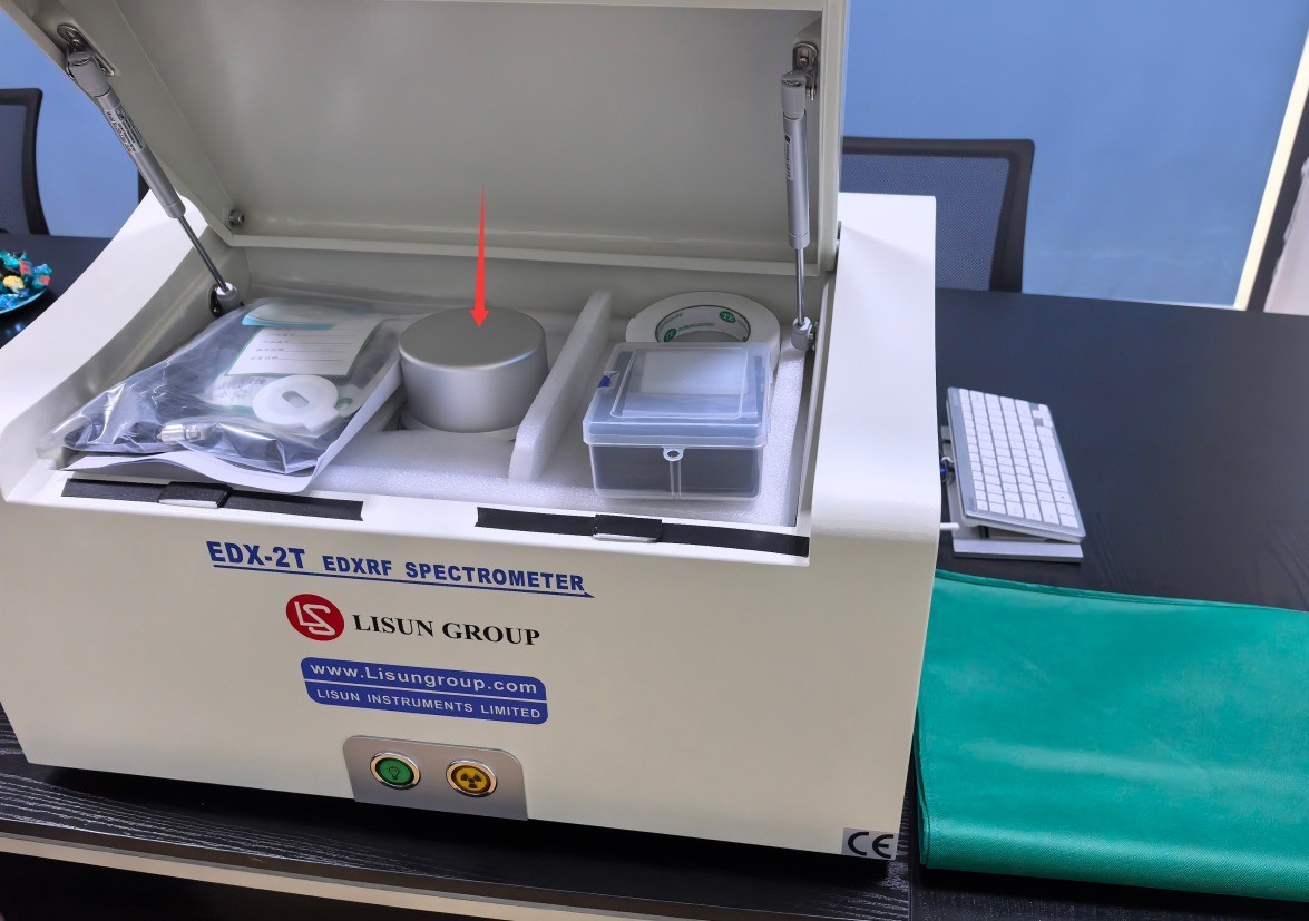
Figures 1–2
1.2.3 Downloading Electronic Documents
We have already sent the download links for the digital user manual, warranty card, and other documents via email at the time of shipment. Please download them as soon as possible. If you missed the email, you can contact us to request the download links again.
2. Safety Precautions
2.1 Electrical Safety
Before connecting the power cord, verify that the supply voltage is AC 220 V ±10% and the frequency is 50 Hz or 60 Hz. You must use a three-prong outlet with a protective ground, and the protective ground resistance must be ≤4 Ω. Never cut or disconnect the protective ground wire, as doing so poses a risk of electric shock.
2.2 Personal Safety Protection
Do not disassemble the instrument without authorization. The equipment is equipped with radiation shielding; disassembly will result in X-ray leakage, which poses a risk to human health.
Designate a specific person to operate the instrument on a full-time basis; unauthorized personnel are prohibited from touching, moving, or operating the equipment.
Before performing any maintenance or cleaning on any component, you must disconnect the main power supply to the host unit to prevent electric shock and damage caused by high voltage.
2.3 Equipment Safety Standards
Do not update the computer’s original operating system or change the system language, as doing so may cause the software to malfunction and become unusable.
If the test film is soiled, it should be replaced promptly. When replacing the film, do not allow your hands or any objects to come into contact with the device’s sensor to prevent damage to critical components;
Do not allow any objects to fall into the device or come into contact with the detector;
The dongle must remain plugged into the computer at all times; the software will not start without it.
2.4 Environmental Safety Requirements
If the temperature of the light tube inside the instrument exceeds 35°C, the software will trigger an alarm; if it exceeds 45°C, the test will automatically stop. It is recommended to keep the room temperature below 25°C.
The work surface on which the instrument is placed must be level, stable, and free of wobble to avoid affecting measurement accuracy.
When the equipment is not in use, cover it with a protective cover to prevent dust from entering; keep the ambient humidity between 40% and 60%.
3. Equipment Assembly
3.1 Vacuum Pump Assembly and Connection (included only with the EDX-2T)
Connect and secure the suction tubing as shown in Figures 3-1 and 3-2.
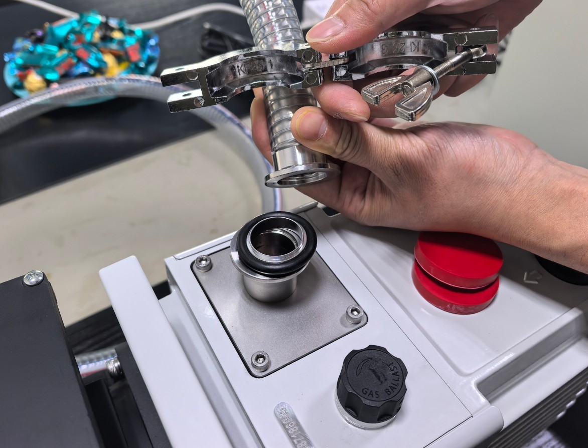
Figure 3-1
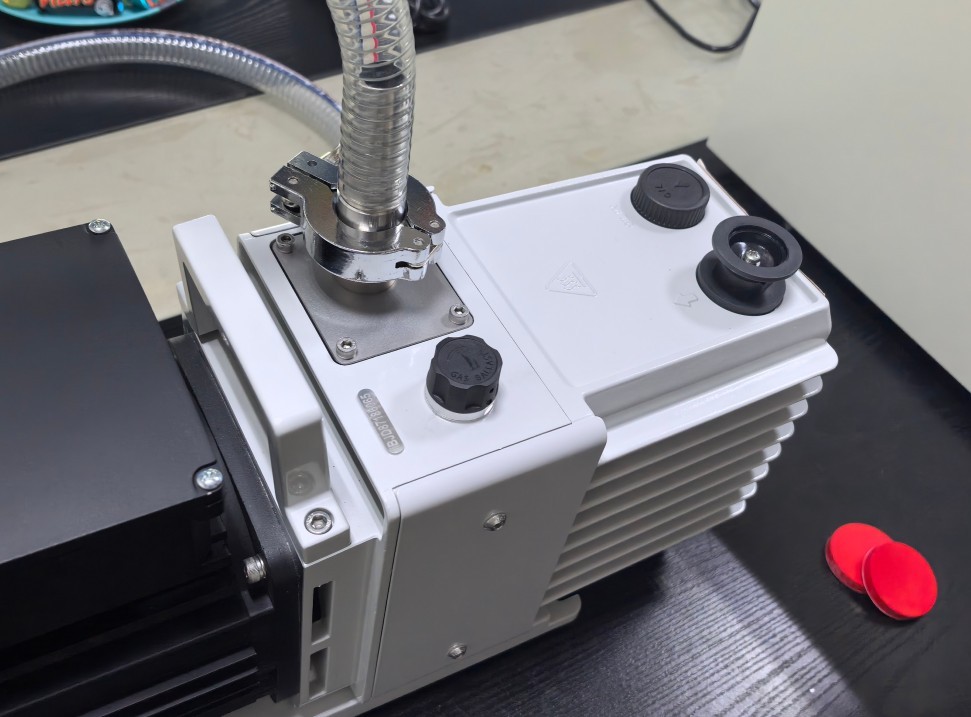
Figure 3-2
Filter connection: Connect and secure the filter as shown in Figures 3-3 and 3-4.
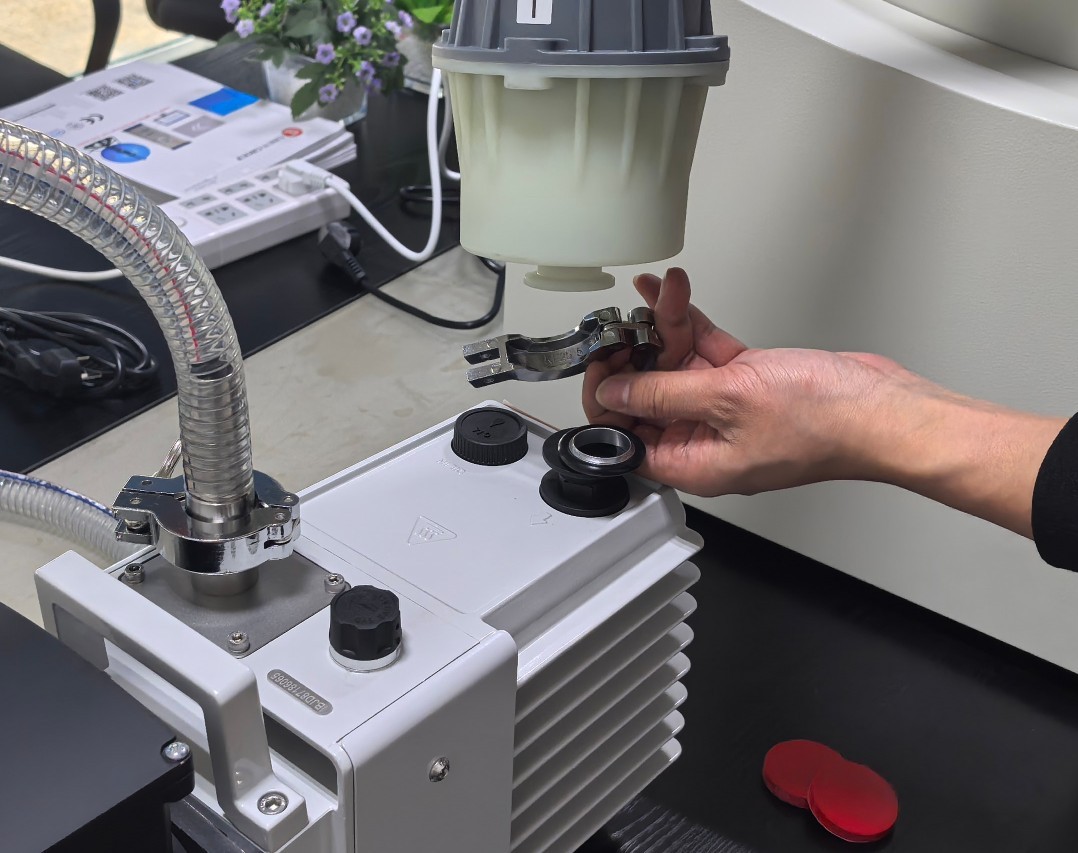
Figure 3-3
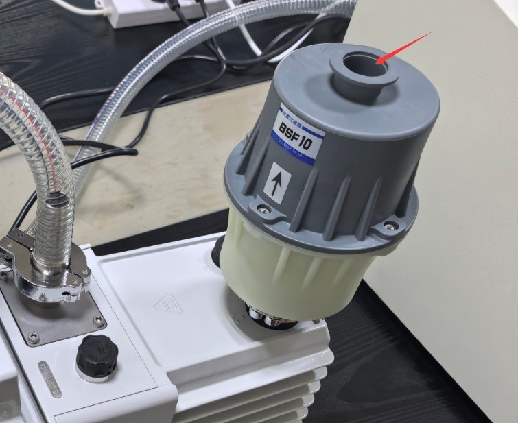
Figure 3-4
Note: See Figures 3–4. Remove the red seal cap when using the device, and replace it when not in use to prevent dust from entering.
Fill with vacuum pump oil, as shown in Figure 3-5.
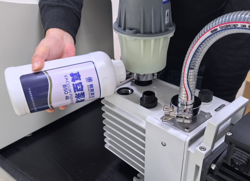
Figure 3-5
Please ensure that the oil level is between the low and high level marks, as shown in Figure 3-6. Add oil to the vacuum pump regularly; do not allow the pump to run dry.
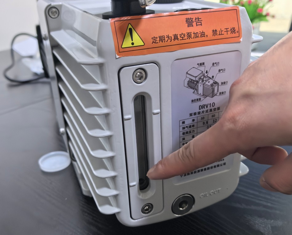
Figure 3-6
For wiring and setup, see Figures 3–7.
| Number | Note |
| ① | Use the special dual-ended power cord: plug one end into a 220V power outlet and connect the other end to the EDX-2T main unit. |
| ② | Power switch: Simply set it to the “I” (On) position; its operating status will be controlled by the EDX-2T software. |
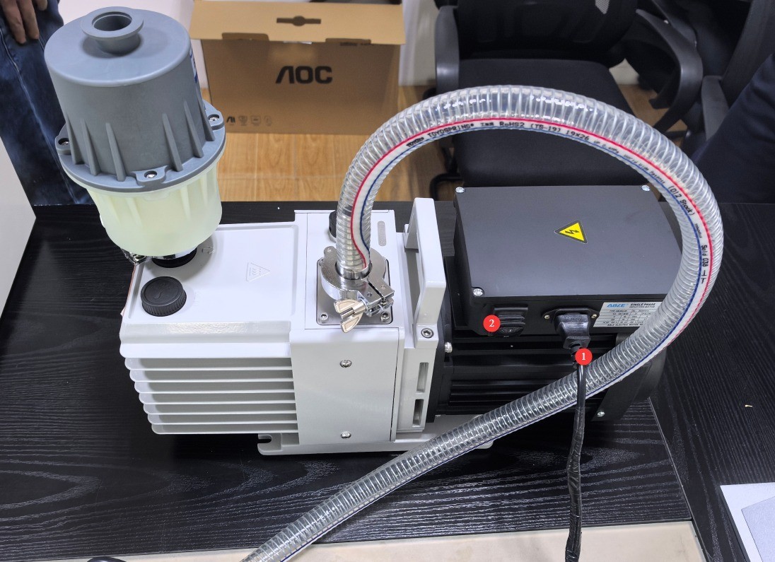
Figure 3-7
3.2 Introduction to and Wiring of the EDX-2 Series Main Unit Rear Panel
See Figures 3–8.
| Number | Note |
| ① | Power Switch |
| ② | Power cord connector: Follow the instructions on the nameplate to connect the device to a 220V power source. |
| ③ | Special dual-end power cord; the other end connects to the vacuum pump. Note: Included only with the EDX-2T. |
| ④ | Vacuum hose connection. Note: Included only with the EDX-2T. |
| ⑤ | USB ports: Please use the standard USB cables provided to connect all devices to the computer. |
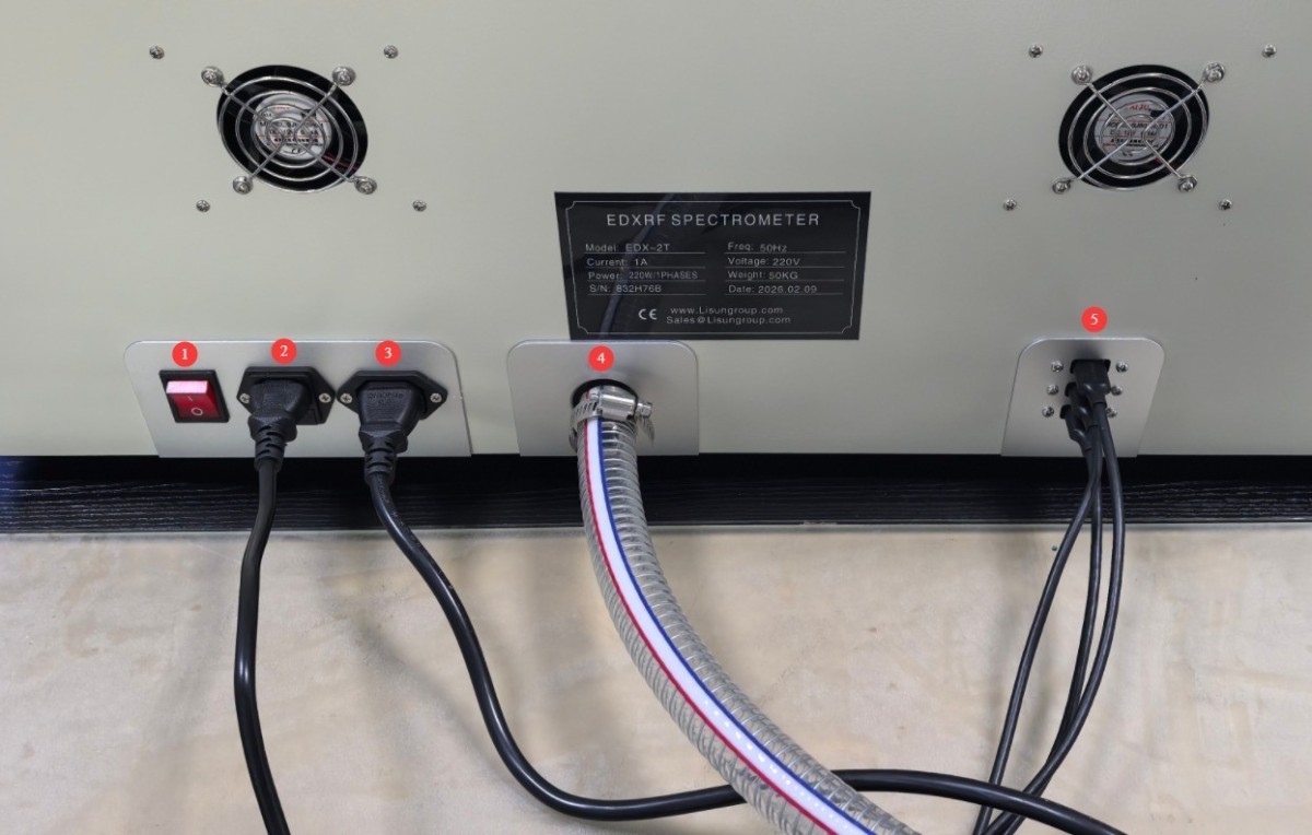
Figure 3-8
3.3 Computer and Printer Assembly
3.3.1 Assembly
For computers and printers, simply follow the instructions in the included manual to assemble and power them on.
3.3.2 Dongle
Please locate the dongle at the position indicated in Figure 3-9 and plug it into a USB port on your computer, as shown in Figure 3-10.
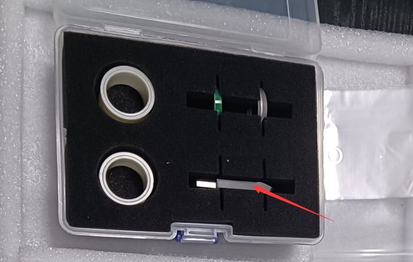
Figure 3-9
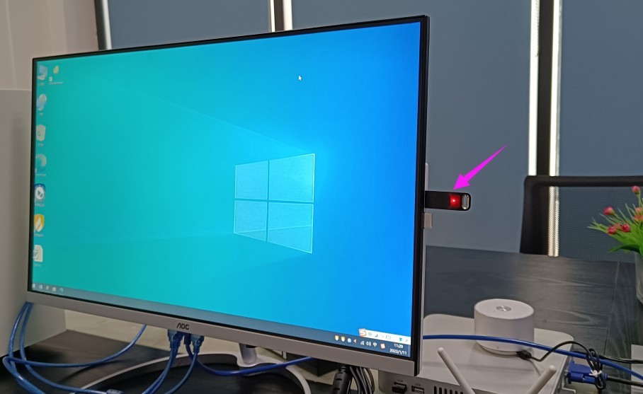
Figure 3-10
3.3.3 Principles for Opening Software
The EDX-2 series devices can have up to three software programs installed, but only one program can run at a time; that is, if you need to run another program, you must first close the program currently running.
4. RoHS Testing Procedure
4.1 Warm-up at Startup
Two minutes after the host computer starts up, double-click the desktop icon (see Figure 4-1) to open the RoHS testing software.
Figure 4-1
If the equipment has been turned off for more than half an hour, it will need to be warmed up before being turned back on; see Figure 4-2.
| Number | Note |
| ① | Click “Preheat,” then wait for the preheating to finish. Preheating takes about half an hour. |
| ② | Displays the software’s current status and a countdown |
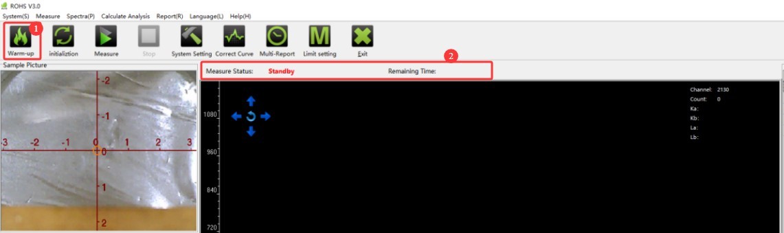
Figure 4-2
4.2 Initialization
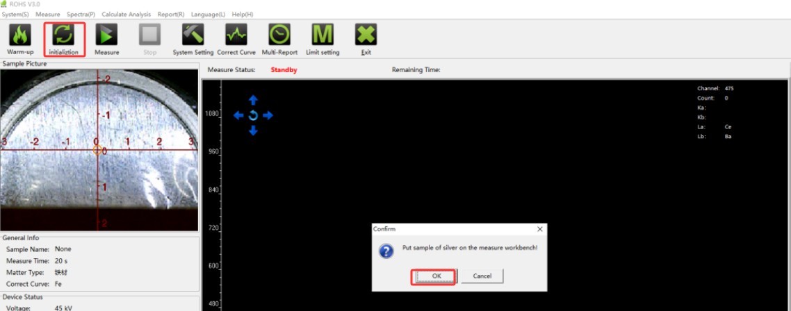
You must run the initialization once after each warm-up; you should also run the initialization once before each test, if possible, to obtain more accurate test results. Refer to Figure 4-3 to locate the silver plate.
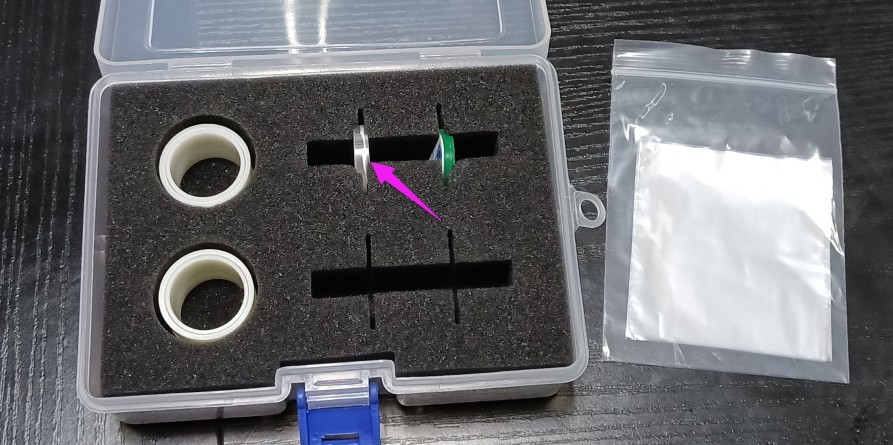
Figure 4-3
Place the sample with the silver side facing down on the test film in the test well, as shown in Figure 4-4, and then close the cover of the EDX-2 series main unit.
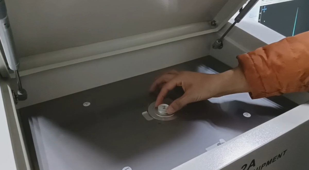
Figure 4-4
See Figures 4 and 5, then click “Initialize” and wait for the initialization to complete. Initialization takes about 10 seconds.
Figures 4–5
4.3 Validation of the EC681M Reference Standard
4.3.1 Testing of Reference Standards
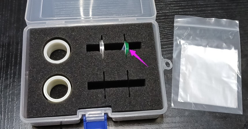
Conduct validation tests using reference samples on a regular basis to confirm that the device’s test results are accurate. As shown in Figures 4–6, remove the reference sample.
Figures 4–6
Place the film with the green side facing down and the printed side facing up on the test film in the test well, as shown in Figure 4-7.
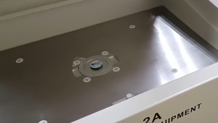
Fig. 4-7
Next, close the cover of the EDX-2 series main unit, then start the test (see Figure 4-8).
| Number | Note |
| ① | Click “Test” |
| ② | Select “PE.” Note: If testing other samples, please select the correct sample material. |
| ③ | Click OK to start the test; the test will end after 200 seconds. |
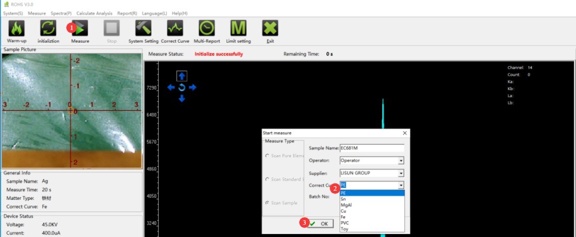
Figure 4-8
The test results confirm this, as shown in Figure 4-9.
| Number | Note |
| ① | Click “Set Limits” |
| ② | You can set limits for each substance. The software has already set default limits in accordance with the standards; however, if you have specific requirements, you can adjust these limits. |
| ③ | If necessary, limit values for total chlorine (Cl) and total bromine (Br) may also be established. |
| ④ | Click to Save |
| ⑤ | The test results show that the units are ppm |
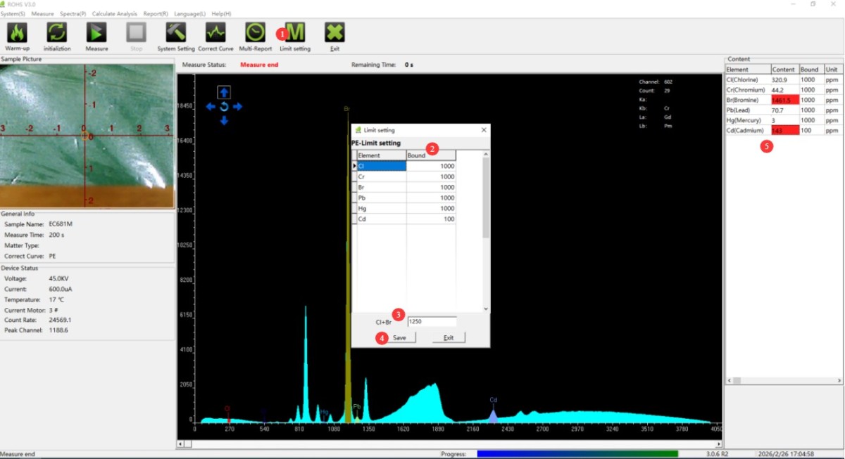
Figure 4-9
Note: Setting the thresholds does not affect the actual test data; it only affects the pass/fail determination. A red display indicates a failure.
To save or print a test report separately, refer to Figure 4-10.
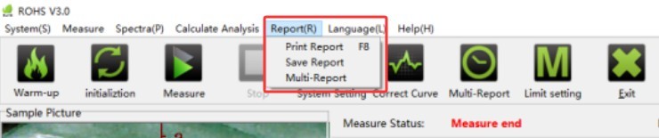
Figure 4-10
4.3.2 Data Comparison
The accessories include a data sheet with test results for the reference standards; see Figure 4-11. The units in the data sheet are 1 mg/kg (equivalent to 1 ppm) and 1 g/kg (equivalent to 1000 ppm); you must convert the units before making comparisons.
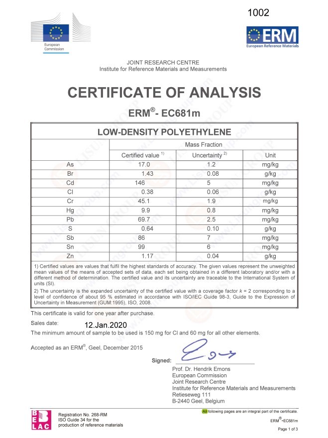
Figure 4-11
Compare the test data with this data table and use the following table of permissible error ranges to determine whether the equipment test results are within normal limits.
| Number | Note |
| Lead (Pb) | Is the content within the range of 69.7 ± 15 ppm? |
| Chromium (Cr) | Is the content within the range of 45.1 ± 10 ppm? |
| Cadmium (Cd) | Is the concentration within the range of 146 ± 21.9 ppm? |
| Mercury (Hg) | Is the concentration between 9.9 and 10 ppm? |
| Bromine (Br) | Is the concentration between 1430 and 219 ppm? |
| Chlorine (Cl) | Is the content within the range of 380 ± 76 ppm? |
Note: The data for our reference samples may vary from batch to batch; please refer to the test data sheet you actually receive. You may still use the table above as a reference for the measurement error range.
4.4 RoHS Sample Testing
4.4.1 Sample Placement
Place the sample on the test window film. Note: If the sample is too small, place multiple samples to completely cover the test window, and then close the EDX-2 Series main unit cover.
If the sample is a powder or liquid, you can use the accessories shown in Figure 4-12 to make your own sample pouch, and then place the pouch in the test window.
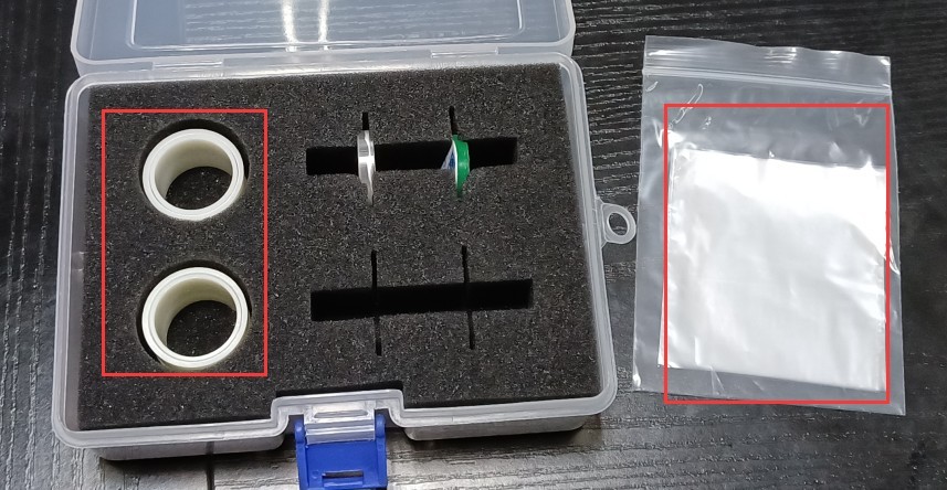
Figure 4-12
4.4.2 Sample Testing
Follow the same procedure as for the reference sample; see Section 4.3.1.
4.4.3 Test Film Replacement
If the test film is stained, replace it promptly. You can remove the metal ring to replace the test film; see Figure 4-13.
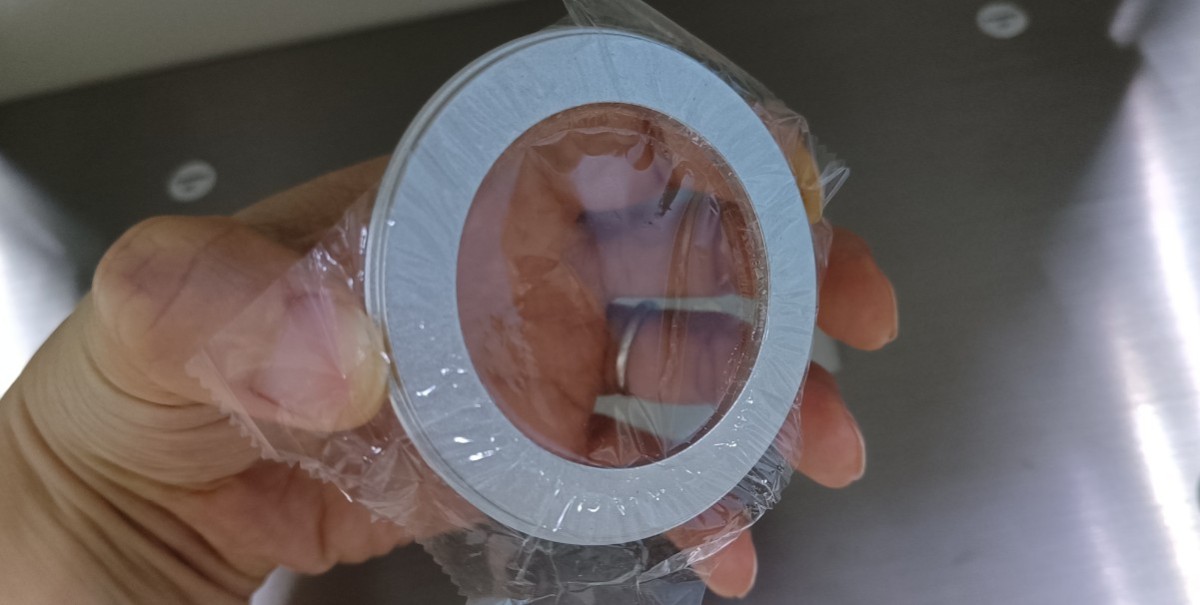
Figure 4-13
Note: When replacing the film, do not allow any objects to fall inside the device, and do not touch the internal sensors.
5. Procedural Steps for Elemental Analysis Testing
5.1 Replacing Test Window Components
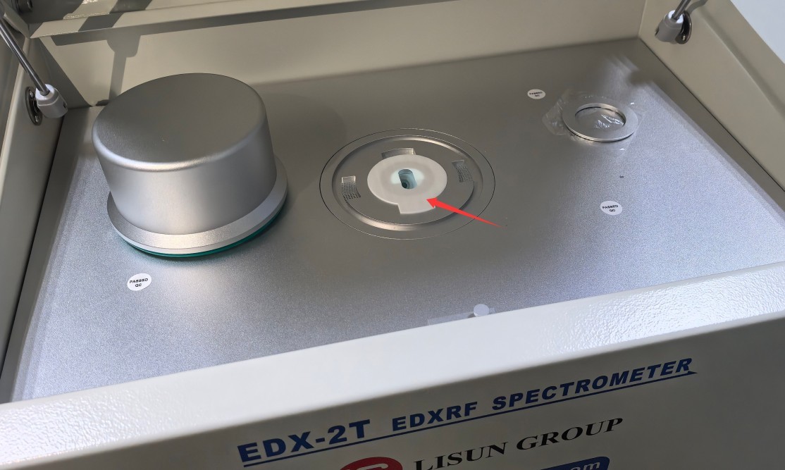
Figure 5-1
Note: The white chuck has an open design; take care to prevent any objects from falling into the device during use.
5.2 Preheating
Turn on the host computer. After 2 minutes, double-click the desktop icon (see Figure 5-2) to open the element testing software.
Figure 5-2
If the device has already been turned on and has completed the warm-up process, you may skip directly to section 5.3.
If the device has been turned off for more than half an hour, it will need to warm up before being turned on again; see Figure 5-3.
| Number | Note |
| ① | Click “Preheat,” then wait for the preheating to finish. Preheating takes about half an hour. |
| ② | Displays the software’s current status and a countdown |
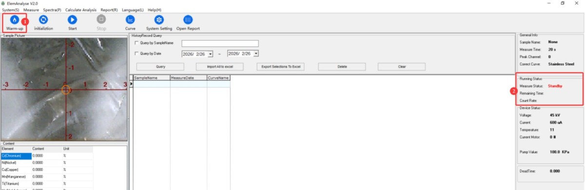
Figure 5-3
5.3 Initialization
An initialization must be performed after each warm-up; an initialization must also be performed each time you switch between different software programs; and, whenever possible, an initialization should be performed before each test to ensure more accurate test results. See Figure 5-4.
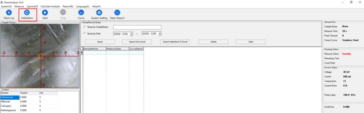
Figure 5-4
The procedure is the same as in Section 4.2.
5.4 Elemental Analysis Testing
5.4.1 Sample Placement
If your device model is EDX-2T, place the sample in the opening of the white chuck, as shown in Figure 5-5.
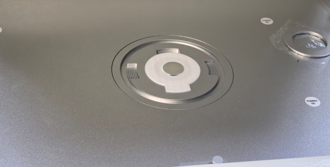
Figure 5-5
Then secure it with the vacuum cover, as shown in Figures 5-6.
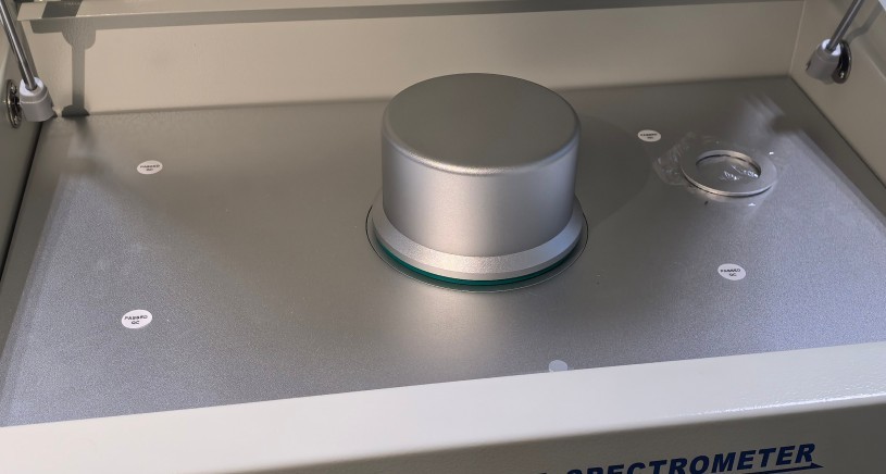
Figures 5–6
Then close the device cover.
If your device model is not EDX-2T, follow the sample placement procedure described in Section 4.4.1.
5.4.2 Sample Testing
See Figures 5–7.
| Number | Note |
| ① | Click “Test” |
| ② | Selecting the Correct Measurement Calibration Curve for the Sample |
| ③ | Check the “Vacuum Pump” box. During testing, the software will automatically control the vacuum pump to perform the test under vacuum conditions. Note: Only the EDX-2T includes this feature; the vacuum is automatically established during testing and automatically released upon completion. Do not release the vacuum manually. |
| ④ | Click OK to start the test |
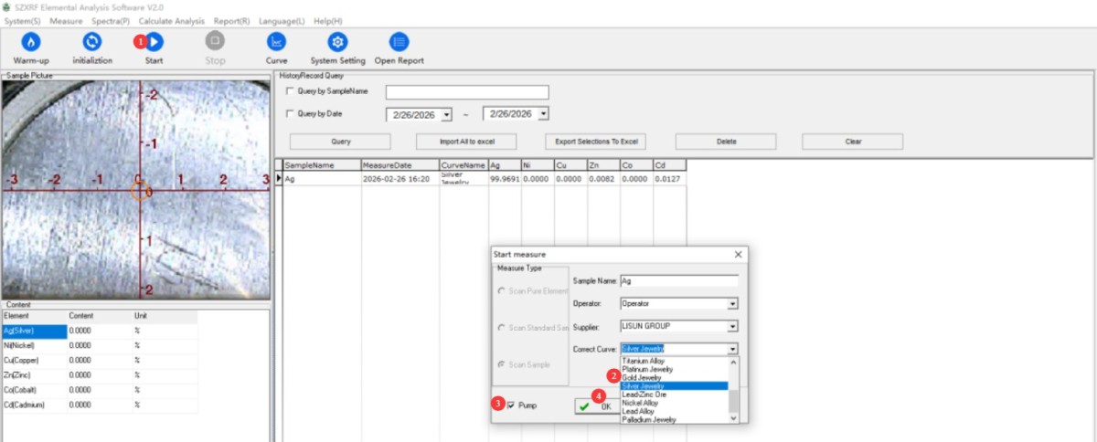
Figure 5-7
To save or print a test report individually, refer to Figures 5–8.
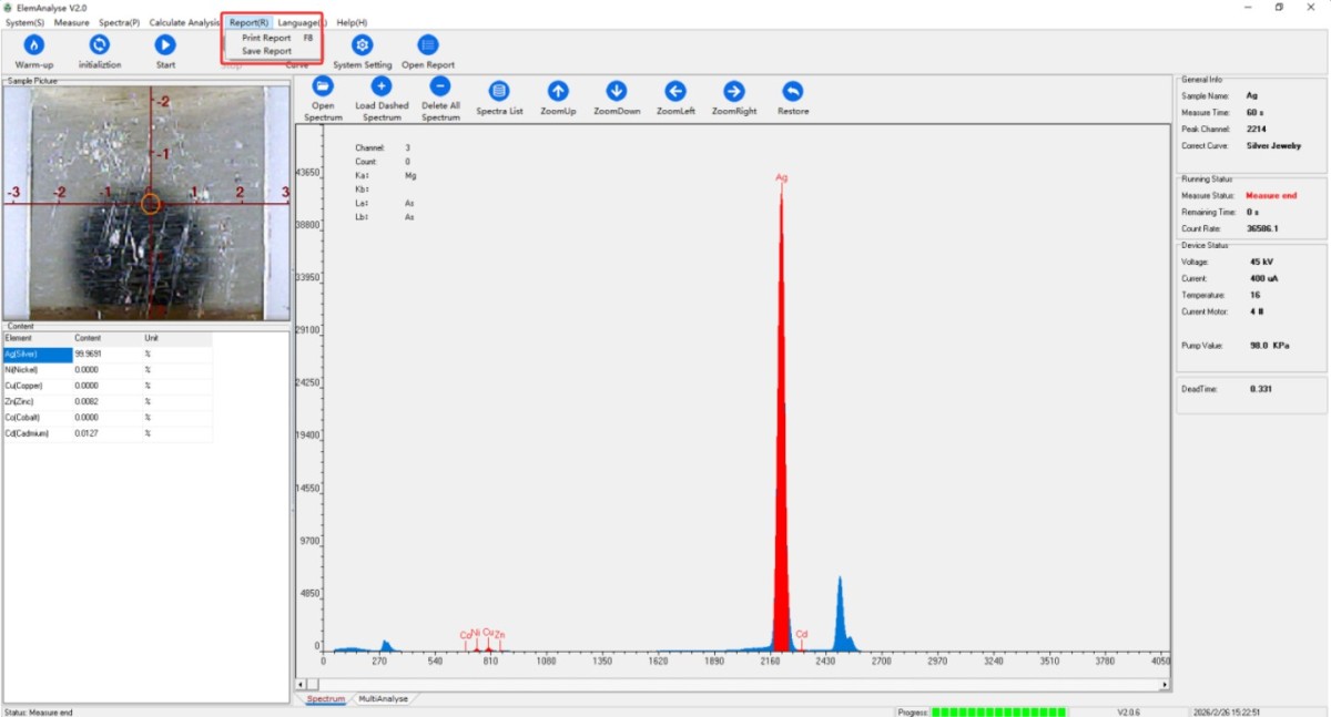
Figure 5-8
6. Operating Procedures for Coating Thickness Analysis and Testing
6.1 Preheating
Follow the same procedure as in Section 5.2. Double-click the desktop icon (see Figure 6-1) to open the coating thickness analysis software.
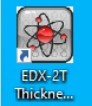
Figure 6-1
See Figure 6-2.
| Number | Note |
| ① | Click “Preheat,” then wait for the preheating to finish. Preheating takes about half an hour. |
| ② | Displays the software’s current status and a countdown |
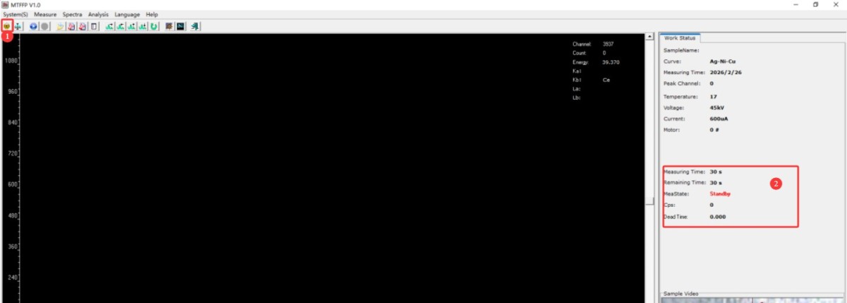
Figure 6-2
6.2 Initialization
Follow the same procedure as in Section 5.3. See Figure 6-3.
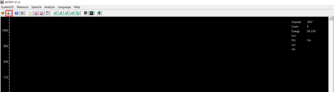
Figure 6-3
6.3 Analysis and Testing of Coating Thickness
6.3.1 Sample Placement
Follow the procedure described in Section 4.4.1.
6.3.2 Sample Testing
See Figure 6.4.
| Number | Note |
| ① | Click “Test” |
| ② | Select the correct measurement calibration curve for the sample. Example: “Ni-Cu” indicates a nickel-plated copper substrate; the same applies to other materials. |
| ③ | Click OK to start the test |
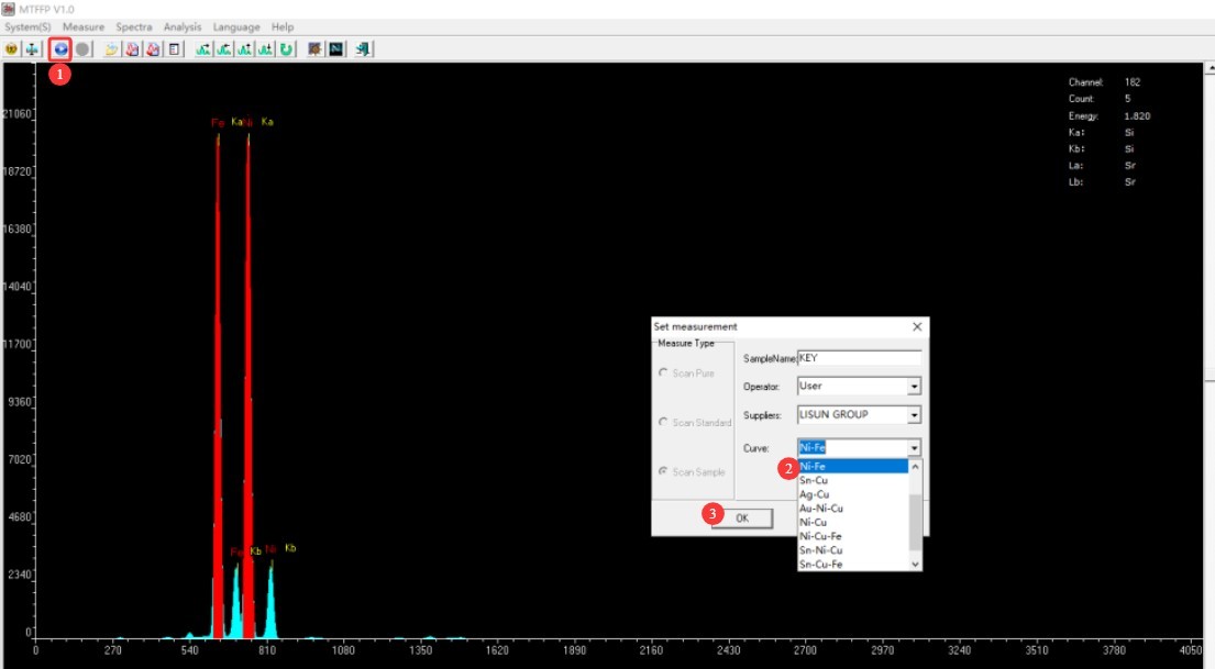
Figure 6-4
To save or print a test report separately, refer to Figure 6-5.
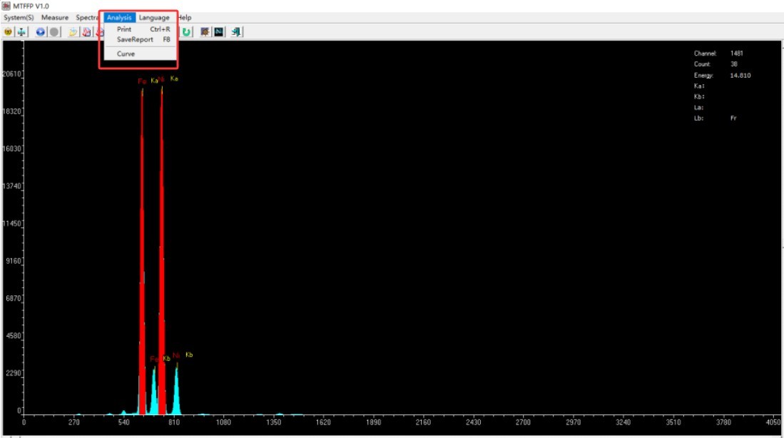
Figure 6-5
7. Daily Maintenance and Care of Equipment
7.1 Daily Cleaning
7.1.1 Cleaning the Test Platform
Dip a cotton swab in a small amount of anhydrous alcohol and gently wipe the test window and the surface of the film to remove stains and powder residue.
7.1.2 Cleaning the Aircraft
Wipe down the main unit’s casing, computer, and printer with a soft cloth to keep them dust-free; do not rinse the main unit directly with liquid.
7.2 Regular Maintenance
7.2.1 Test Film Replacement
If the film is torn, soiled, or yellowed, replace it immediately with the original film included with the product or food-grade plastic wrap.
7.2.2 Temperature Check
Check the temperature alerts in the software during daily testing. If the temperature exceeds 35°C, stop using the device and resume testing after it has cooled down.
7.2.3 Verification of Reference Samples
Conduct a weekly calibration using the EC681M standard sample to ensure the equipment’s accuracy remains stable.
7.3 Long-Term Storage
7.3.1 Dust Protection
If the unit will not be used for an extended period (more than 7 days), cover the entire unit with the dedicated protective cover and unplug the power cord.
7.3.2 Storage Conditions
Store in a dry, well-ventilated area away from direct sunlight and corrosive gases, at a temperature of 15–28°C.
7.4 Parts Management
7.4.1 Storage of Silver Plates
Store in a special storage box to prevent scratches and staining, and keep the silver surface shiny.
7.4.2 Storage of Test Films
Store in an airtight container to protect against moisture, wrinkles, and dust.
7.4.3 Dongle Protection
Avoid bending or dropping it; when not in use, plug it into your computer or store it in its carrying case.
8. Troubleshooting and Resolving Common Problems
| Fault Symptoms | Possible Causes | Procedure |
| The software won’t start | Dongle not plugged in, loose USB connection, or changes made to the computer’s operating system | Plug in the dongle; check the USB connection; restore the computer to its original system settings or contact us for remote assistance. |
| Initialization Failed | Silver plate is upside down, cover plate is not in place, film is contaminated | Place it back with the silver side facing down; secure the cover plate; replace the film with a clean one; and try initializing again. |
| Significant Deviations in Test Data | Not preheated / Not initialized, film contamination, sample not covering the window | Preheat + Initialize; Replace the film; Retry after the sample fully covers the window |
| Test Interrupted | Temperature too high; cover opened | Wait until it cools down before taking another measurement; make sure the cover is securely closed before taking another measurement. |