
 English
 中文简体
中文简体 English
 Русский
 Español
 Português
 Türkçe
 العربية
 Deutsch
 Polski
 Italiano
 Français
 한국어
한국어 ไทย
ไทย Tiếng Việt
 日本語
日本語





























Tungsten/Halogen Lamp Load Cabinet
User's Manual
Applicable LISUN models: DFX-WD20A
1. Unboxing and Basic Familiarization with the Equipment
1.1 Key Technical Specifications
1.1.1 DFX Tungsten Filament Lamp Load Cabinet
Power Supply: Single-phase AC 220 ± 10% / 50 Hz with ground wire;
Digital Voltmeter: Range 0–300 V, accuracy ±0.5% ±2d;
Digital ammeter: Range 0–40 A, accuracy ±0.5% ±2d;
Digital Power Meter: Range 0–9 kW, Accuracy ±0.5% ±2d;
Load Configuration: Built-in 3 sets of multi-bulb 200W tungsten/halogen lamp combinations, with cyclic power supply;
Number of output channels: 1;
Load capacity: 7.5 kVA;
The maximum output current is 20 A; the load is automatically disconnected when the current exceeds 22 A;
The maximum output voltage is 300 V; when it exceeds 305 V, the load is automatically disconnected;
Selecting the number of tungsten filament lamps/halogen lamps: Each lamp has a power rating of 200 W, available in sets of 1, 2, 3, 4, 10, or 10 lamps;
Counter: Preset range of 0 to 999999;
Features a long-stick protection function: The upper limit for long-stick time can be preset from 0 to 99 seconds.
1.1.2 CZKS Series Socket and Switch Life Test Machine
| LISUN Model | CZKS-3 | CZKS-3P | CZKS-3S | CZKS-3A |
| Workstation | 2 Outlets + 1 Switch | 3-outlet outlet | 3 Switches | 1 Outlet + 2 Switches |
| Drive Type | Pneumatic drive; customer-supplied air source: 0.8 MPa | |||
| Control Methods | PLC + Extra-Large Touchscreen | |||
| Turn-on/Turn-off Time | 0–99.9 seconds per minute (adjustable) | |||
| Number of Tests | 0–999999 times (preset) | |||
| Test Run | Linear: -40 to 110 mm (presettable); Rotation: 0 to 360° (presettable) | |||
| Test Rate | Linear: 0–100 mm/s (preset); Rotational: 0–90°/s (preset) | |||
| Sample Fixture | Comes standard with a universal clamp that can be adjusted up and down (other special clamps can be custom-made according to customer requirements) | |||
| LISUN Model | CZKS-6 | CZKS-6P | CZKS-6S | CZKS-6X |
| Workstation | 3 Outlets + 3 Switches | 6-outlet outlet | 6 Switches | Custom Number of Outlets + Switches |
| Drive Type | Pneumatic drive; customer must provide their own air supply: 0.8 MPa | |||
| Control Methods | PLC + Extra-Large Touchscreen | |||
| Turn-on/Turn-off Time | 0–99.9 seconds per minute (adjustable) | |||
| Number of Tests | 0–999999 times (preset) | |||
| Test Run | Linear: -40 to 110 mm (presettable); Rotation: 0 to 360° (presettable) | |||
| Test Rate | Linear: 0–100 mm/s (preset); Rotational: 0–90°/s (preset) | |||
| Sample Fixture | Comes standard with a universal clamp that can be adjusted up and down (other special configurations can be customized according to customer requirements) | |||
1.2 Unboxing Inspection and Verification of Accessories
1.2.1 Unpacking and Visual Inspection
When unpacking the device, handle it gently to avoid scratching the casing with sharp tools. After unpacking, first inspect the exterior of the device to ensure there is no visible deformation or dents, and that the buttons are not damaged or loose.
If you notice any damage or deformation to the equipment or accessories, do not turn on the power. Please contact us immediately.
1.2.2 Main Unit and Accessories
Load cabinet: 1 unit; CZKS life tester: 1 unit.
Standard accessories: 200W tungsten bulbs—52 in total (32 for the load cabinet, with the remaining 20 as spares).
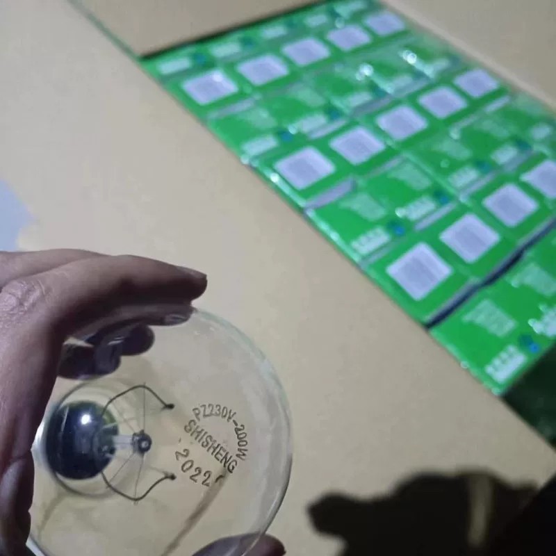
Figure 1
Note: The LISUN switch life tester must be used in conjunction with an air compressor. Users may purchase one from LISUN or provide their own. If providing your own, please ensure it is capable of delivering compressed air at 0.8 MPa. An air hose with an 8 mm outer diameter is required for connection to the switch life tester.
Download links for the digital user manual, warranty card, and other documents have been sent to you via email. Please download them as soon as possible. If you missed the email, please feel free to contact us to request the download links again.
1.3 Description of Equipment Structure
1.3.1 Load Cabinet
Front of the load cabinet:
① Load (tungsten filament lamp) voltage display; ② Load current display; ③ Load power display; ④ Number of tests: the top line shows the current number of tests performed, and the bottom line shows the set total number of tests;⑤ Long-duration stick-on protection time: the top line shows the current load on-time, and the bottom line shows the set long-duration stick-on time. Once the load’s single on-time reaches the set long-duration stick-on time, the load cabinet will sound an alarm and automatically cut off the output; ⑥ Load cabinet power switch; ⑦ Load power switch;⑧ Tungsten filament lamp quantity selector switch; combinations can be freely configured as needed; ⑨ Enable load output; ⑩ Disable load output; ⑪ Load on/off indicator light / Alarm reset button; ⑫ Alarm; ⑬ Cooling fan switch; ⑭ Load voltage adjustment dial.
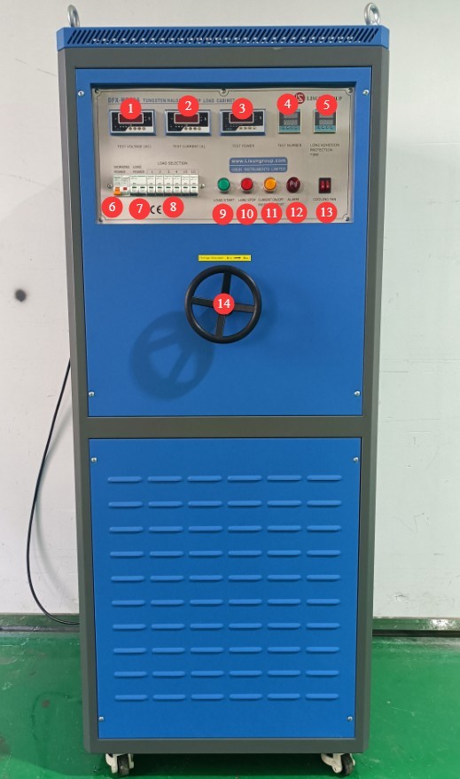
Figure 2
Left side and interior of the load cabinet:
① Tungsten filament lamp mounting slots—please install tungsten filament lamps in all 32 slots before use; ② Cooling fan; ③ Power cord for the load cabinet.
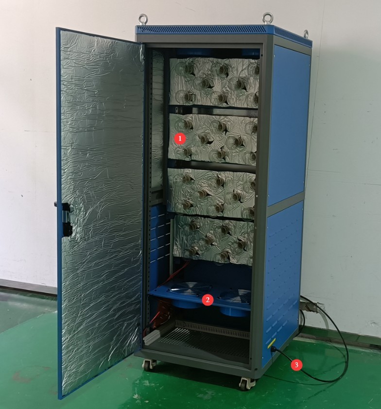
Figure 3
Right side of the load cabinet:
① The three terminals on the left are used to connect a separate power supply to power the tungsten filament lamp; ② The four terminals on the right are used to connect to the switch life tester and the test switch.
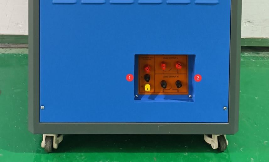
Figure 4
1.3.2 Life Test Machine
The life test machines are available in two series: the 3-station CZKS-3 and the 6-station CZKS-6. There are two types of fixtures: fixtures for testing sockets and fixtures for testing switches. Taking the CZKS-6 model as an example:
① Touchscreen; ② Power switch; ③ Switch fixture; ④ Outlet fixture; ⑤ Terminal block; ⑥ Circuit breaker; ⑦ Power cord receptacle; ⑧ Air compressor connection.
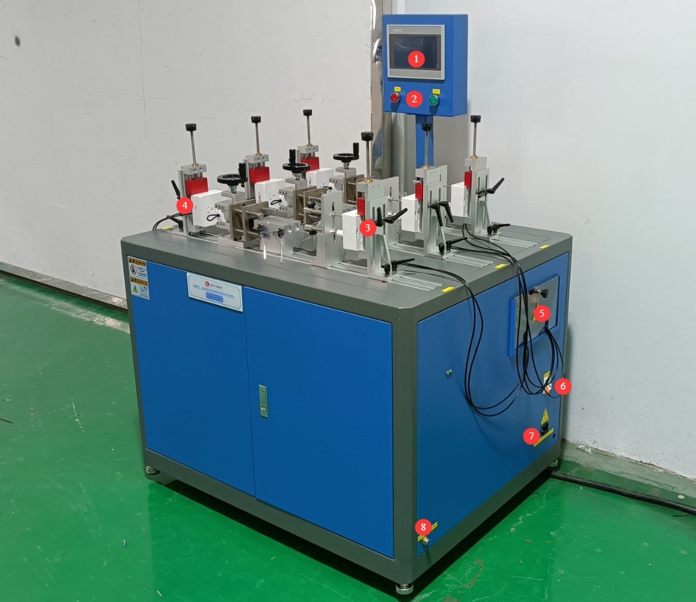
Figure 5
2. Safety Precautions
2.1 Electrical Safety
2.1.1 Power Connection
220V single-phase power; power outlets must comply with safety standards, have proper grounding, and have a rated current that matches the equipment’s power rating.
Note: The load cabinet itself does not have a high power rating; its maximum current is less than 1 A. However, tungsten filament lamps draw a significant amount of power when in operation. Please check the nameplate and the markings on the terminal blocks, and select a suitable power supply.
2.1.2 Grounding Specifications
The equipment must be reliably grounded, with a grounding resistance of ≤4 Ω. Do not use gas pipes, non-metallic water pipes, or neutral wires as substitutes for the grounding wire. After grounding is complete, use a Grounding Resistance Tester to measure the grounding resistance. Power may only be applied after confirming that the requirements are met, to prevent electric shock, equipment malfunctions, or measurement errors caused by poor grounding.
2.2 Operational Safety
Before wiring, inspecting, or maintaining equipment, you must turn off the equipment’s power switch and the main power supply, and confirm that there is no residual voltage before proceeding;
Do not operate the equipment’s power switch, touchscreen, or instrument buttons with wet hands to avoid the risk of electric shock;
Do not place any foreign objects (such as tools or paper) inside the electrical control cabinet to prevent dust or foreign objects from causing short circuits or damaging components;
Do not plug in or unplug power cords or signal cables while the equipment is running, to prevent short circuits that could damage the controller or electrical components.
2.3 Environmental Safety
The equipment should be placed in a dry environment free of corrosive gases and flammable or explosive materials.
The equipment must be installed in an air-conditioned room, with the ambient temperature maintained between 5°C and 35°C and relative humidity ≤ 85%.
The distance between the equipment and walls, as well as surrounding structures (such as other testing equipment and shelving), must be at least 1000 mm to facilitate maintenance; at least 2000 mm of space must be left in front of the equipment to ensure smooth operation and keep the surrounding area free of obstructions;
The equipment must be placed on a level, sturdy surface; the height of the equipment’s legs is adjustable.
2.4 Other
For matters not covered in this manual, please proceed with caution or contact us.
3. Introduction to the Touchscreen Program for the Life Test Machine
3.1 Work Page
① Manual/Automatic Switch; ② Start/Stop Test; ③ Station List.
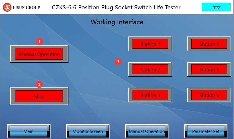
Figure 6
3.2 Parameter Settings Page
① Page navigation; ② Total number of tests; ③ Load on time; ④ Load off time; ⑤ Number of failed current monitoring attempts; ⑥ Whether current is being monitored.
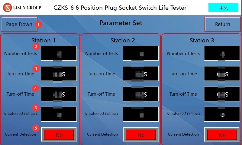
Figure 7
Note: Users can set different parameters for different workstations.
3.3 Manual Window
Click the manual control button for the corresponding workstation to manually adjust the position of the fixture at that workstation.
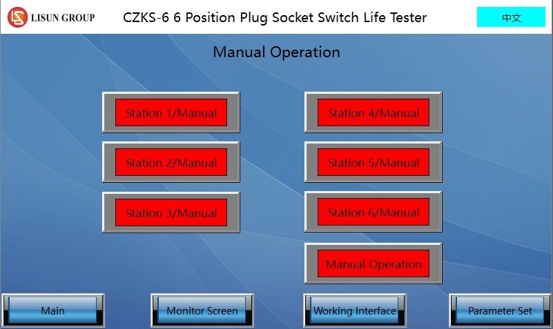
Figure 8
3.4 Surveillance Footage
① Page navigation; ② Run/Pause; ③ Monitor current; ④ Total number of tests; ⑤ Number of tests performed; ⑥ Number of current monitoring sessions; ⑦ Reset.
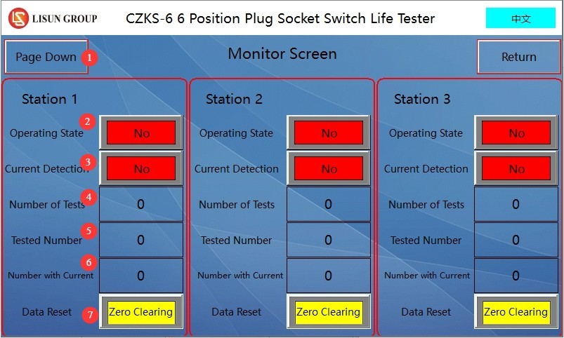
Figure 9
4. Preparations Before the Test
4.1 Equipment Wiring
4.1.1 Power Cord Connection
Please refer to Chapter 2. Turn on the life-cycle tester; do not turn on the load cabinet at this time.
4.1.2 Air Compressor Connection
Connect an air hose with an outer diameter of 8 mm to the endurance testing machine, then turn on the air compressor.
4.1.3 Connecting the Load Cabinet, Endurance Tester, and Specimen
The load cabinet has the following four terminals—two red and two black—as shown in the figure below.
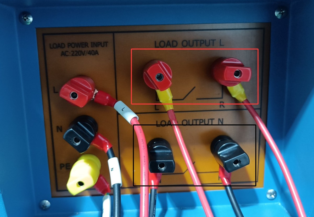
Figure 10
4.1.3.1 Single-Pole Switch
Connect the two red terminals or the two black terminals of the load cabinet to the life tester, and then short-circuit the other two terminals.
The two terminals on the load cabinet are connected to terminals A and B on the life testing machine, and terminals A and C on the life testing machine are connected to the sample switch, as shown in the wiring diagram for workstation 4 of the life testing machine below.
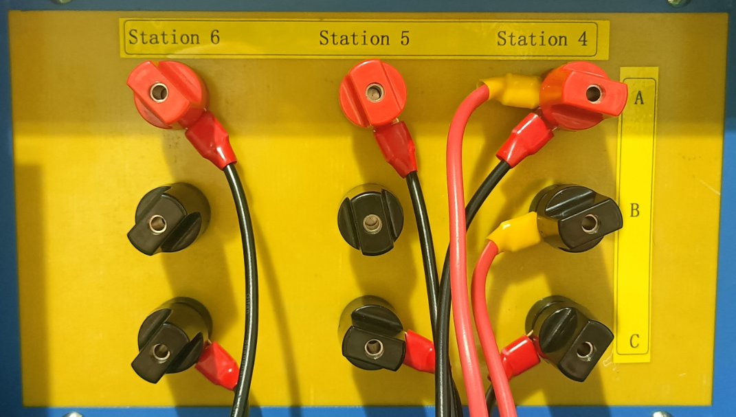
Figure 11
4.1.3.2 Dual-Control Switch
Connect the two terminals on the load panel that are short-circuited directly to one circuit of the double-pole switch, and then connect the other circuit of the double-pole switch as described in section 4.1.3.1.
4.2 Sample Calibration
Open the manual window of the life test machine. Click the button for the corresponding test station to perform a single-cycle operation, then observe the position of the machine’s actuators. If the test specimen is a switch, adjust the machine so that when the upper actuator extends, it just closes the switch, and when the lower actuator extends, it just opens the switch.
After debugging is complete, the switch should be set to the off position.
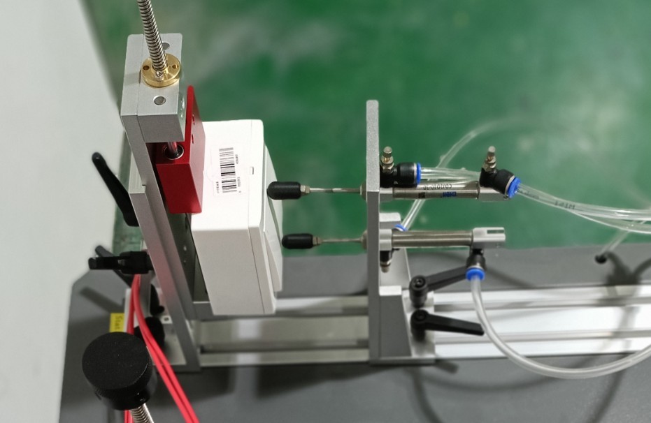
Figure 12
5. Switch Life Test Procedure
5.1 Load Cabinet Configuration
Turn on the power switch for the load cabinet.
The number of test cycles is factory-set to 9999, and the adhesive holding time is factory-set to 90 seconds. Users can also adjust these settings as needed.
Turn on the load cabinet’s power switch, press the “Start Load Output” button, and turn on all cooling fans.
Slowly rotate the voltage adjustment dial while monitoring the test voltage until the voltage meets the test specifications. Note: When the load voltage exceeds 305 V, the device will automatically disconnect the load.
Turn on the tungsten filament lamp quantity selector switch as needed; with a maximum load of 30 tungsten filament lamps (if switches 1, 2, 3, 4, 10, and 10 are all turned on, the total number of tungsten filament lamps in use is 1 + 2 + 3 + 4 + 10 + 10 = 30). Users may also freely combine switches according to their needs.
Example: According to Clause 18.3 of standard GB/T 16915.1-2024 (IEC 60669-1:2017, Clause 18.3), when testing a 10 A, 250 V switch, the voltage required for a 200 W tungsten filament lamp is 240 V, and 15 such lamps are required.
In the manual window of the life test machine, turn on the switch for the corresponding workstation. See the figure below:
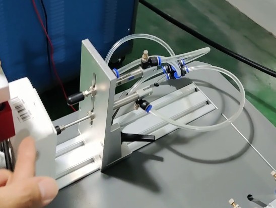
Figure 13
After the switch is turned on, the voltage will drop slightly, requiring you to turn the voltage adjustment knob again. At this point, the test load current is 1.2 times the rated current of the sample switch, or approximately 12 A. Note: When the load current exceeds 22 A, the load cabinet will automatically disconnect the load.
Once the adjustment is complete, go to the manual control panel of the endurance tester and return the specimen to its original state by setting the specimen switch to the “OFF” position.
5.2 Setting Up the Life Test Machine
Parameter Settings Interface. For each workstation, configure the total number of tests, load on time, load off time, number of failed current monitoring attempts, and whether to monitor current.
Note 1: The number of faults refers to the number of times the sample was energized but no current was detected (the test will automatically stop once the actual number of faults during the test reaches the set fault limit; this parameter is invalid when current monitoring is disabled);
Note 2: Current monitoring should only be enabled when a load cabinet is connected to that test station for testing.
Monitoring Interface. Used to view the test status and data for the corresponding workstation. Please click the “Reset” button for the corresponding workstation to clear the previous test data before you can begin testing at that workstation.
5.3 Life Test
5.3.1 Starting the Test
Go to the work interface. ① Select the workstation you want to run, ② click to switch from manual to automatic, ③ click to start the test.
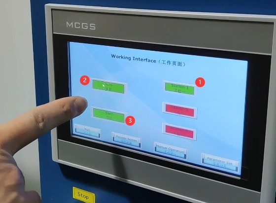
Figure 14
5.3.2 Test Monitoring
During the test, you can view real-time data on the monitoring screen.
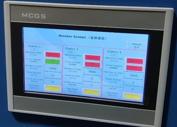
Figure 15
5.3.3 End of the Test
If the number of test cycles at a life test machine station reaches the set limit, that station will stop the test and automatically place the specimen in the disconnected state. Important note: The load cabinet is still outputting power; please turn off the load output before proceeding.
If the life tester station is equipped with selective current monitoring and the number of failures during the test reaches the preset limit, the life tester will automatically stop the test at that station and automatically disconnect the test specimen. Important Note: The load cabinet will still be in the output state; please turn off the load output before proceeding with any further operations.
If a sample at a test station on the life tester is damaged during testing and remains in the “always on” state, the load cabinet will trigger an alarm after the load has been continuously applied for 90 seconds and will automatically cut off the output. Please press the alarm reset button on the front panel of the load cabinet and manually end the test for the corresponding station on the life tester.
6. Post-Test Procedures
6.1 Viewing Recorded Test Data
Access the life test machine monitoring screen, check and record the test data for each station.
6.2 Shutting Down
Turn off the air compressor;
Turn off the life-cycle testing machine;
Disconnect the load output from the load cabinet, turn off the cooling fan, reset the tungsten lamp quantity selector switch to its original position, and turn off the power to the load cabinet.
6.3 Check the Sample Condition
Use a screwdriver to loosen the clamp screws, remove the tested sample, inspect the sample’s appearance (e.g., check for deformation of the socket and plug, or ablation of the switch contacts), and record the test results.
7. Daily Maintenance and Care of Equipment
7.1 Cleaning and Maintenance
After the test is complete, wipe down the life-test machine fixtures and other components with a dry cloth; do not use corrosive cleaning agents. Remove dust from the equipment’s terminal blocks to prevent poor contact.
7.2 Lubrication and Maintenance
Apply lubricating oil to the sliding components of the endurance testing machine (slide rails, cylinder piston rods) to ensure smooth mechanical operation; check the fixture screws and tighten any loose parts promptly.
7.3 Equipment Storage
7.3.1 Short-Term Storage Requirements
If the equipment is used on a daily basis, no further action is required after cleaning is completed following each test.
7.3.2 Long-Term Storage Requirements
If the device will not be used for an extended period (more than one month), please disconnect all cables and cover the device with a dust cover to prevent dust buildup.
The device should be powered on once a month for just half an hour to prevent the aging of electrical components (such as capacitors and contactors).
8. Troubleshooting and Resolving Common Problems
8.1 Failures in Life Testing Machines
8.1.1 The testing machine has no mechanical movement
Causes of malfunction: Insufficient air supply pressure < 0.8 MPa, air leak at the air supply connection, or malfunction of the cylinder solenoid valve;
Solution: Adjust the air compressor pressure to 0.8 MPa, replace the leaking air supply hose, and contact the manufacturer to repair the solenoid valve.
8.1.2 No Display on the Touchscreen / Touchscreen Not Responding
Causes of the malfunction: Power not connected, loose touchscreen ribbon cable, PLC program error;
Troubleshooting: Check the power connections on the testing machine and firmly reconnect the touchscreen ribbon cable. If there is a software error, contact the manufacturer for assistance.
8.1.3 The Workstation Fails to Start
Cause of failure: Current monitoring failure, short circuit in the sample wiring, or the number of tests or failures has reached the preset value;
Solution: Check the sample wiring, click the “Reset” button on the monitoring screen, and replace the current detection module if it is damaged.
8.2 Load Cabinet Failure
8.2.1 No Voltage/Current Output
Causes of malfunction: Main power not turned on, voltage knob not adjusted, loose terminal connections;
Procedure: Turn on the main power supply to the load cabinet, adjust the voltage knob to the rated value, and tighten the terminal screws.
8.2.2 Abnormal Display in the Electrical Parameters Table
Causes of malfunction: Corrupted parameter table, stuck voltage dial, poor sample contact;
Solution: Replace the electrical parameter meter, remove any debris from the turntable, and reinstall the sample to ensure proper contact.
8.2.3 Continuous Equipment Alarms
Causes of malfunction: Sample current remains active for more than 90 seconds, load overload, or a malfunctioning alarm reset button;
Troubleshooting: Check for a short circuit in the sample, reduce the load current to the rated value, and replace the alarm reset button.
8.3 Joint Test Failures
Failure Symptom: Frequent failures of test specimens during electrical life testing
Cause of the malfunction: Load parameters do not meet standard requirements; deviation in the sample installation position;
Solution: Readjust the current and power factor of the load cabinet to the standard values, and adjust the mechanical position of the testing machine to ensure good contact with the sample.