
 English
 中文简体
中文简体 English
 Русский
 Español
 Português
 Türkçe
 العربية
 Deutsch
 Polski
 Italiano
 Français
 한국어
한국어 ไทย
ไทย Tiếng Việt
 日本語
日本語





























Steel Ball Impact Test
User's Manual
Applicable LISUN models: LS-B33
1. Unboxing and Basic Familiarization with the Equipment
1.1 Key Technical Specifications
| Parameters | Note |
| Steel Ball Dimensions | Φ50 mm |
| Steel Ball Material | GCr15 bearing steel (magnetic) |
| Steel Ball Quality | 500±25 g or 510 g |
| Impact Height | Adjustable from 0 to 1.5 m |
1.2 Unboxing and Checking the Contents
1.2.1 Unpacking and Visual Inspection
When unpacking the device, handle it gently to avoid scratching the outer casing with sharp tools. After unpacking, first inspect the exterior of the device to ensure there is no visible deformation or dents, and that the buttons are not damaged or loose. If you notice any abnormalities with the device or its accessories, do not turn it on. Please contact us immediately.
1.2.2 Main Unit and Accessories
| Number | Note |
| ① | LS-B33 Steel Ball Impact Test Main Unit |
| ② | Power Cord |
| ③ | Steel balls, 2 in total. One is a drop ball, used for vertical impact testing; the other is a pendulum ball, equipped with a suspension ring and a special steel cable, used for horizontal impact testing. |
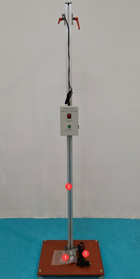
Figure 1
Download links for the digital user manual, software, warranty card, and other materials have been sent via email. Please download them as soon as possible. If you missed the email, please feel free to contact us to request the download links again.
1.3 Scope of Application of the Equipment
This equipment is designed in accordance with Appendix T.6 and Figure T.1 of GB/T 4943.1-2022, Clause 15.3.3 of GB 9706.1-2020, andClause 4.13.4 of GB/T 7000.1-2023. It supports two test modes—vertical drop impact and horizontal swing impact—to simulate the collision and impact scenarios that the equipment enclosure may encounter during actual use and transportation.
2. Safety Precautions
2.1 Electrical Safety
2.1.1 Power Supply Requirements
Use a single-phase AC 220 V ±10%, 50/60 Hz three-prong outlet; the ground prong must be connected to ground.
2.1.2 Grounding Requirements
The instrument ground wire is reliably connected to the protective ground wire, and the protective ground resistance is ≤4 Ω.
2.2 Environmental Safety
2.2.1 Temperature and Humidity Requirements
Avoid using this device in environments where humidity exceeds 70% (where condensation is likely to occur) or where the temperature falls outside the range of 0–35°C. The optimal operating temperature is 25±2°C.
2.2.2 Environmental Contraindications
Environments with strong magnetic fields and strong electric fields;
Environments containing corrosive gases or liquids;
Areas with flammable and explosive dust, and areas containing hazardous materials;
Environments with heavy dust, high temperatures and humidity, and direct sunlight.
2.3 Operational Safety
Operators must be familiar with the instruction manual;
Wear safety goggles during testing; do not under any circumstances extend your hands or head into the area where the steel ball strikes;
The test area must be free of debris; unauthorized personnel are prohibited from approaching. Ensure there is sufficient operating space to prevent accidental injury;
Do not leave the electromagnet powered on for extended periods to prevent the coil from burning out.
3. Equipment Overview and Assembly
3.1 Rear-side View
| Number | Note |
| ① | Power Cord Connection |
| ② | Power Switch |
| ③ | Electromagnet, used to pick up steel balls that have fallen |
| ④ | Release button: Press to release the steel ball and perform the vertical impact test. |
| ⑤ | Installation of Steel Cables and Pendulum Balls |
| ⑥ | Steel Ball Mounting Bracket, Height-Adjustable |
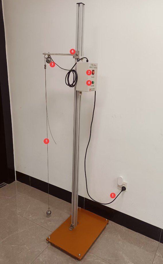
Figure 2
3.2 Front View
A ruler, used as a reference to verify the impact height.
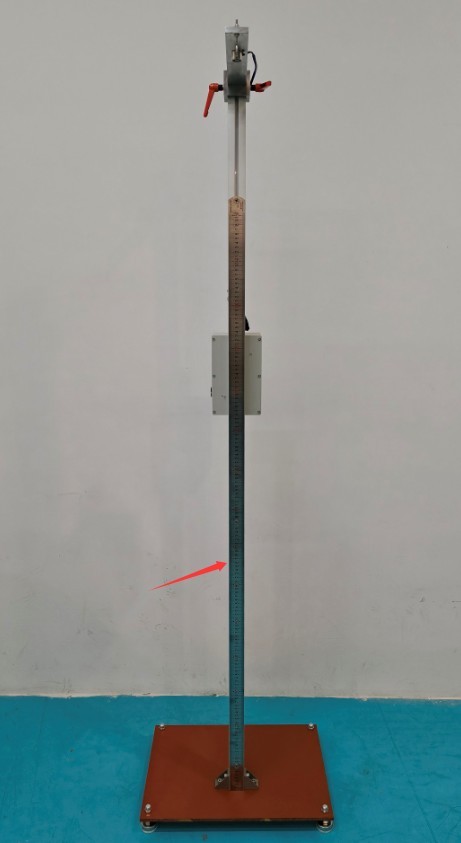
Figure 3
4. Preparations Before the Test
4.1 Preparing the Environment
Place the equipment on a level surface and level the frame; clean the test bench to ensure that the sample support surface is rigid and flat.
4.2 Sample Preparation
The specimen must be securely clamped in accordance with the standard; shaking is prohibited. Determine the impact location (vulnerable surfaces or areas prone to impact). The specimen’s surface must be clean and free of damage that could affect the test.
4.3 Parameter Verification
Confirm the impact mode: drop test/swing test; confirm the impact height: 1.3 meters, for example (or refer to the applicable standard).
5. Steel Ball Impact Test
5.1 Vertical Impact Test with a Steel Ball (Equipment must be powered on)
5.1.1 Sample Placement
Place the sample on the rigid support surface directly beneath the steel ball; adjust its position so that the impact point aligns with the target test location.
5.1.2 Impact Height Adjustment
Adjust the height of the steel ball mounting bracket, use a steel ruler to verify that the free fall height is 1.3 meters, and tighten the bracket screws.
5.1.3 Placement of Steel Balls
Connect the power cord and turn on the main unit’s power switch; place the steel ball directly beneath the electromagnet and make sure it is securely attached.
5.1.4 Impact Execution
Evacuate all unauthorized personnel to a safe area; press the release button to de-energize the electromagnet and release the steel ball, thereby completing the vertical impact test. If the steel ball bounces back, catch it to prevent a secondary impact.
If no further vertical impact tests are required, turn off the power switch on the equipment.
5.1.5 Verification of Test Results
Observe the sample’s appearance, structure, protective performance, and other characteristics in accordance with the standard requirements.
5.2 Horizontal Impact Test with a Pendulum Steel Ball (No power required for the equipment)
5.2.1 Sample Placement
Place the sample within the swing path of the oscillating steel ball.
5.2.2 Steel Rope Adjustment
Adjust the length of the steel cable attached to the pendulum ball to ensure that the ball strikes the target point precisely when it falls.
5.2.3 Steel Ball Height Adjustment
Lift the pendulum so that the point where it falls is 1.3 meters vertically above the impact point; keep the steel cable taut, with no slack.
5.2.4 Impact Enforcement
Gently release the steel ball; it will strike the specimen along the swing path, completing the horizontal impact test. If the steel ball rebounds, catch it to prevent a secondary impact.
5.2.5 Verification of Test Results
Observe the sample’s appearance, structure, protective performance, and other characteristics in accordance with the standard requirements.
6. Daily Maintenance and Care of Equipment
6.1 Routine Maintenance (After Each Test)
Store the steel ball and steel cable separately and securely; return the steel ball mounting bracket to its original height; remove the test specimen; wipe down the equipment surface, support platform, and control panel with an antistatic, dry cloth; check that the steel ball is not deformed and the steel cable shows no signs of wear; confirm that the electromagnet is not overheating and does not emit any unusual odors.
6.2 Regular Maintenance (Once a Month)
Apply grease or rust-preventative oil to the steel balls and electromagnets to prevent rust; inspect the adjustable mounting brackets and add lubricant; tighten all loose screws and joints.
6.3 Storage and Maintenance (During Extended Periods of Non-Use)
Store in a dry, well-ventilated environment with humidity ≤ 75%; remove all steel balls and store them separately to prevent rust; turn off the main power supply and cover the equipment with a dust cover; do not subject the equipment to heavy pressure or impact.
7. Troubleshooting and Resolving Common Problems
| Failure Symptoms | Possible Causes | Procedure |
| Severe overheating of the electromagnet | Prolonged power-on, coil aging | Turn off the power immediately and reduce the duration of each power-on cycle; contact us to replace the coil parts. |
Appendix A: Comparison Table of Relevant National Standard Test Requirements
| Standard Number | Relevant Provisions | Steel Ball Specifications (Diameter + Mass + Material + Requirements) | Impact Height | Test Method | Test Requirements | Determination of Results |
| GB/T 4943.1-2022 | Appendix T.6, Figure T.1 | Φ50 mm, weight 500 g ± 25 g, GCr15 bearing steel (magnetic), with the pendulum ball equipped with a suspension ring | 1.3 m (vertical clearance, measured from the bottom of the steel ball to the impact surface of the specimen) | Vertical ball drop (flat impact) and swinging ball (direct impact)—choose between the two methods as needed | Samples must be rigidly secured with no looseness; the impact points are the weakest and most impact-prone areas of the product’s casing, and each impact point is struck only once. | No damage that poses an unacceptable risk; the housing has no breaks or cracks, its protective function remains intact, and it does not affect the normal operation of the equipment. |
| GB 9706.1-2020 | 15.3.3 | 1.3 m (vertical distance from the center of the steel ball to the impact surface of the specimen) | Vertical drop test (flat specimen), horizontal pendulum impact test (flat specimen); only one impact per relevant area | For finished products or representative components without reinforced parts, use rigid supports in their normal operating positions; this does not apply to flat-panel displays or flat glass used in ME equipment. | No ongoing damage that poses an unacceptable risk; the housing shows no permanent deformation or cracks, and the electrical safety and functionality of the equipment are not affected. | |
| GB/T 7000.1-2023 | 4.13.4 | Φ50 mm, weight 0.51 kg (510 g), GCr15 bearing steel (magnetic) | 1.3 m (vertical free-fall height, no initial velocity, from the bottom of the steel ball to the impact surface of the specimen) | Only vertical ball impact; the direction of impact is perpendicular to the sample’s impact surface; each vulnerable area is impacted once, with no additional initial velocity. | The luminaire housing must be securely fastened so that it does not wobble; the impact areas are the vulnerable parts of the luminaire housing (such as the lampshade and the corners of the housing). Samples must be clean and undamaged, and the support surface must not provide any cushioning. | The housing shows no structural cracks and has not been opened; the internal components show no displacement or damage; the protection rating remains unchanged; the lamp functions normally and is safe to use; and there is no risk of electrical leakage. |