
 English
 中文简体
中文简体 English
 Русский
 Español
 Português
 Türkçe
 العربية
 Deutsch
 Polski
 Italiano
 Français
 한국어
한국어 ไทย
ไทย Tiếng Việt
 日本語
日本語





























Multiplex Temperature Tester
User's Manual
Applicable LISUN models: TMP-16、TMP-8
1. Unboxing and Basic Familiarization with the Equipment
1.1 Key Technical Specifications
| Product Model | TMP-8 | TMP-16 |
| Number of Channels | 8 | 16 |
| Thermocouple Types | Type K | |
| Thermocouple Compensation Cable Length | 3 meters (other lengths available upon request) | |
| Temperature Test Range | -40 to 300°C | |
| Temperature Measurement Accuracy | 0.5% | |
| Features | Individual channel control, multi-channel cyclic monitoring, single-channel monitoring | |
| Computer Software | Can save test data and temperature curves, and print test reports | |
1.2 Unboxing and Checking the Contents
1.2.1 Unpacking and Visual Inspection
When unpacking the device, handle it gently to avoid scratching the casing with sharp tools. After unpacking, first inspect the exterior of the device to ensure there is no visible deformation or dents, and that the buttons are not damaged or loose. If you notice any abnormalities with the device or its accessories, do not power it on. Please contact us immediately.
1.2.2 Main Unit and Accessories
Host: 1 TMP-8.16 Multiplex Temperature Tester.
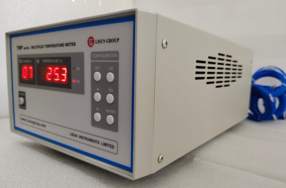
Figure 1
The standard accessories are as follows:
| Number | Note |
| ① | Thermocouple junction box. The TMP-8 includes 1, and the TMP-16 includes 2. |
| ② | RS-232 Communication Cable |
| ③ | Power Cord |
| ④ | RS-232 to USB Adapter Cable |
| ⑤ | Spare 0.5A fuse |
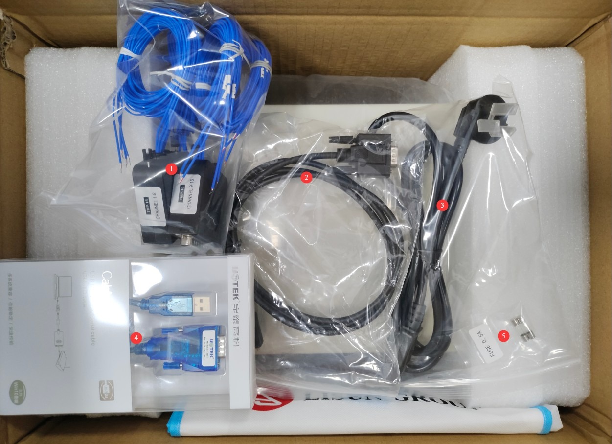
Figure 2
Download links for the digital user manual, software, warranty card, and other materials have been sent via email. Please download them as soon as possible. If you missed the email, please feel free to contact us to request the download links again.
2. Safety Precautions
2.1 Electrical Safety
2.1.1 Power Connection
Single-phase power supply: AC 220 V ±10%. Power outlets must comply with safety standards, have proper grounding, and have a rated current that meets the equipment’s power requirements. Ensure that all connections are secure and free of looseness.
2.1.2 Grounding Specifications
The equipment must be reliably grounded, with a grounding resistance of ≤4 Ω. Do not use gas pipes, non-metallic water pipes, or the neutral wire as a substitute for the ground wire. This will prevent electric shock, equipment malfunctions, or measurement errors caused by poor grounding.
2.2 Operational Safety
Before wiring, inspecting, or maintaining the equipment, you must disconnect the main power supply to the equipment and confirm that there is no residual voltage before proceeding;
When moving instruments, handle them with care to avoid violent vibrations or impacts, and place them securely on a stable surface;
Do not operate the equipment’s power switch, touchscreen, or instrument buttons with wet hands to avoid the risk of electric shock; do not plug in or unplug power cords, communication cables, or thermocouple junction boxes while the equipment is running.
2.3 Environmental Safety
The use of this instrument in explosive atmospheres or areas where flammable and explosive materials are stored is strictly prohibited to prevent safety incidents;
The instrument’s operating environment must meet the following requirements: temperature 0–50 °C, relative humidity 20%–90%, free of corrosive gases and strong electromagnetic interference, and no heat sources behind the instrument;
Avoid exposing thermocouples to high temperatures exceeding 300°C for extended periods to prevent material degradation from affecting measurement accuracy.
2.4 Other
For matters not covered in this manual, please proceed with caution or contact us.
3. Hardware Operations
3.1 Instrument Operation
3.1.1 Introduction to and Operation of the Front Panel
| Number | Note |
| ① | Power Switch |
| ② | Current Channel Display |
| ③ | Real-time temperature display for this channel |
| ④ | When the CM light is on, it indicates that the device is currently in the scanning measurement mode; when the SM light is on, it indicates that the device is currently in the fixed-point measurement mode. |
| ⑤ | SET: Set the channels to be monitored; you can enable the required channels or disable the ones you don’t need; the instrument’s communication baud rate; the instrument’s communication address. Note: Do not modify the baud rate or address without authorization, as this may cause software malfunctions. ∧: Select a channel when configuring巡检channels; toggle between baud rates when configuring the baud rate. >: Enable or disable a channel when configuring巡检channels; when setting the baud rate, select the baud rate CM: Causes the instrument to measure the temperature of each channel according to the preset巡检 channels SM: Sets the instrument to perform a spot measurement of the current channel’s temperature; at this point, you can use the “∧” or “>” keys to select the channel for spot measurement ENTER: Press this key to confirm and save the settings |
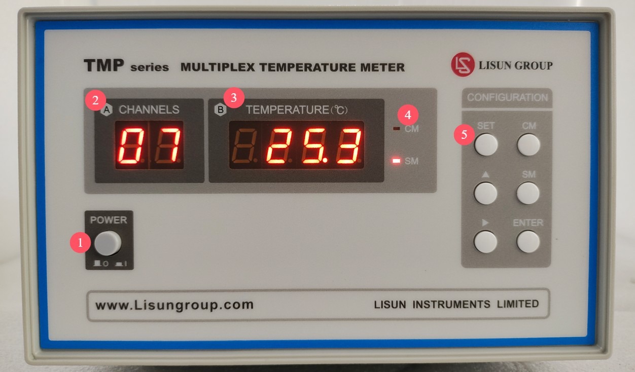
Figure 3
Note: If a channel is disabled, it will be automatically skipped during temperature checks.
3.1.2 Introduction to and Operation of the Back Panel
| Number | Note |
| ① | Thermocouple Sockets 1 through 8 |
| ② | 1-to-8-Channel Thermocouple Connector |
| ③ | 9- to 16-Channel Thermocouple Sockets |
| ④ | 9- to 16-Channel Thermocouple Connector |
| ⑤ | RS-232 Communication Port: If you need to use software on your computer, connect the device to your computer using an RS-232 cable or an RS-232-to-USB adapter. |
| ⑥ | Ground terminal, fuse, power cord receptacle Note: If the ground wire of the power cord is already connected to the ground, there is no need to connect a separate ground wire to the ground terminal. |
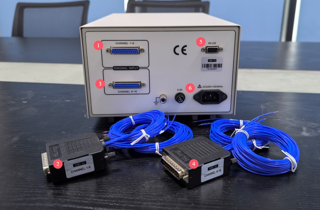
Figure 4
Note 1: The TMP-8 is a 8-channel Multiplex Temperature Tester, and the TMP-16 is a 16-channel Multiplex Temperature Tester. Note 2: Thermocouple plugs for channels 1 through 8 must not be inserted into sockets for channels 9 through 16, and thermocouple plugs for channels 9 through 16 must not be inserted into sockets for channels 1 through 8; otherwise, the temperature display will be abnormal.
3.2 Connecting the Thermocouple to the Sample
You can use the following high-temperature-resistant instant adhesive to connect the test probe at the tip of the thermocouple lead wire to the measurement point. If the test probe breaks after use and can no longer be used, simply cut off the top portion, strip the insulation from both wires, and short-circuit them directly to continue using the lead wire.

Figure 5
4. Software Operation
4.1 Software Installation
4.1.1 Computer Hardware Requirements
Hardware: Pentium or higher processor, at least one USB port (or one RS232 port);
Operating System: Windows 7 or later.
4.1.1 Installation Steps
Copy the software folder to your computer, then double-click to install the Multiplex Temperature Tester software.

Figure 6
Double-click to install the RS232-to-USB adapter driver.
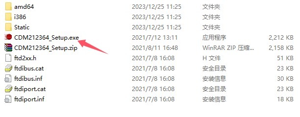
Figure 7
4.2 Steps for Using the Software Core
4.2.1 Display Settings
Products Under Test and Test Information.
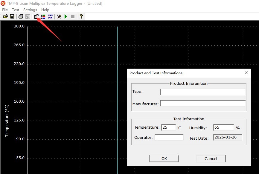
Figure 8
Display and print options.
| Number | Note |
| ① | Check the boxes next to the channels you want to display and print |
| ② | Customize the name of each channel to make them easier to distinguish |
| ③ | Customize the display color for each channel |
| ④ | Time display options. Absolute time: Set the time directly to the current time displayed on the computer; Relative time: Set the time when the test begins as 0. |
| ⑤ | Web Display |
| ⑥ | Do you need a color report? |
| ⑦ | Once you’ve finished configuring the settings, click OK to save them. |
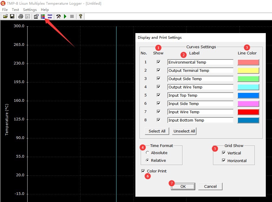
Figure 9
4.2.2 Test Parameter Settings and Testing
System Settings.
| Number | Note |
| ① | Communication Address. Verify that this matches the communication address displayed by the instrument in section 3.1.1; otherwise, the software will be unable to communicate. |
| ② | Communication baud rate. Verify that it matches the communication baud rate displayed in Section 3.1.1; otherwise, the software will be unable to communicate. |
| ③ | Communication Port. Click “Auto Search” to have the software automatically search for the correct port. |
| ④ | You can check the boxes next to the channels you want to enable for testing; channels that are not checked will be disabled during testing. |
| ⑤ | Set the total test duration |
| ⑥ | Set the sampling interval duration |
| ⑦ | Once you’ve finished configuring the settings, click OK to save them. |
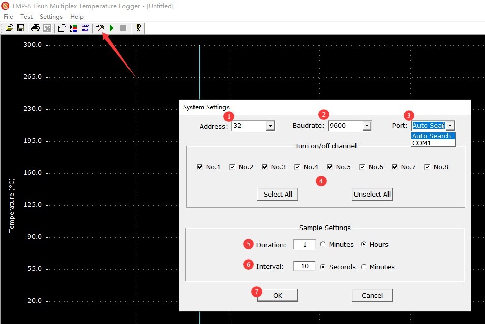
Figure 10
| Number | Note |
| ① | Click to start the test |
| ② | Click to stop the test |
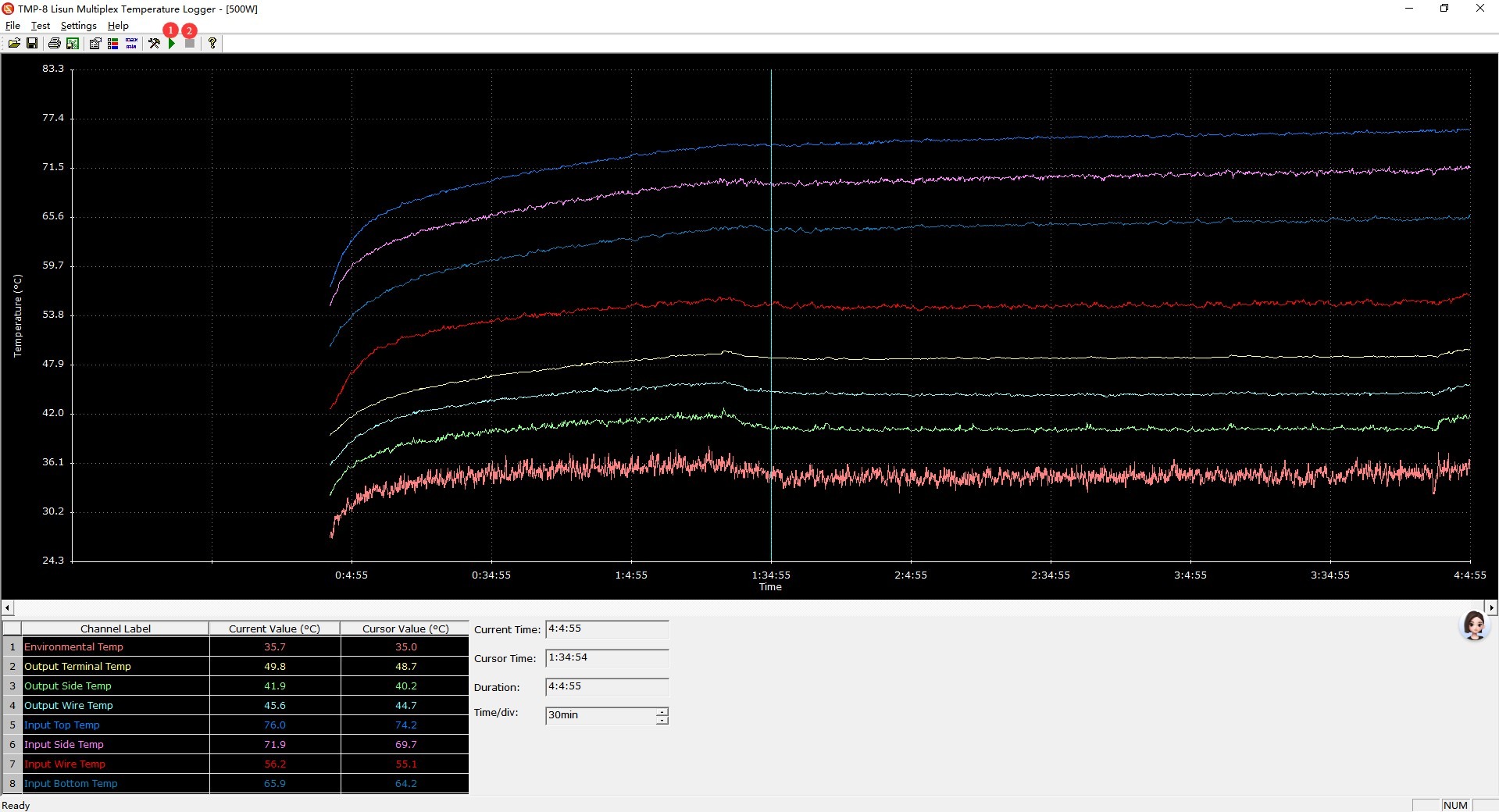
Figure 11
Note 1: When a software-based communication instrument is performing a test, the instrument’s front panel displays only the word “COM” to indicate that communication is in progress.
Note 2: Channels that have been disabled in the software are also disabled on the instrument. This means that if you later perform a test using the instrument without controlling it via the software, that channel will remain disabled and will be automatically skipped. Refer to Section 3.1.1 to re-enable the channel on the instrument.
4.2.3 Saving and Exporting Test Data
Click “Save” to save the test data as a TLF-format file; this file format can only be opened using the TMP Multiplex Temperature Tester software.
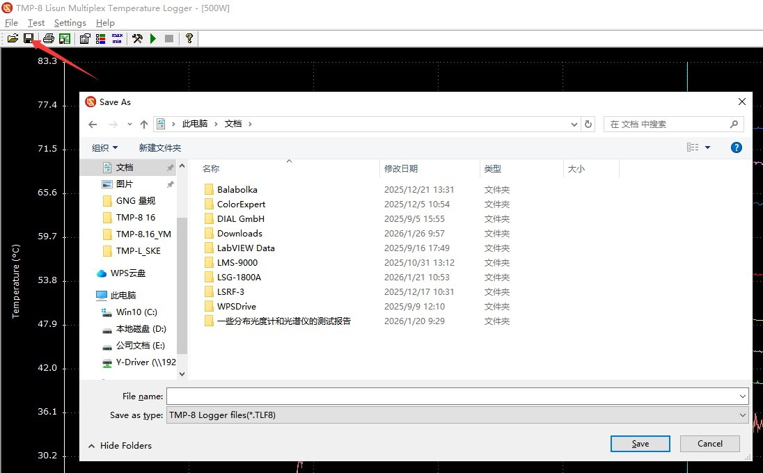
Figure 12
| Number | Note |
| ① | Click to print the test report on paper or as a PDF |
| ② | Click to export the detailed test report to Excel. |
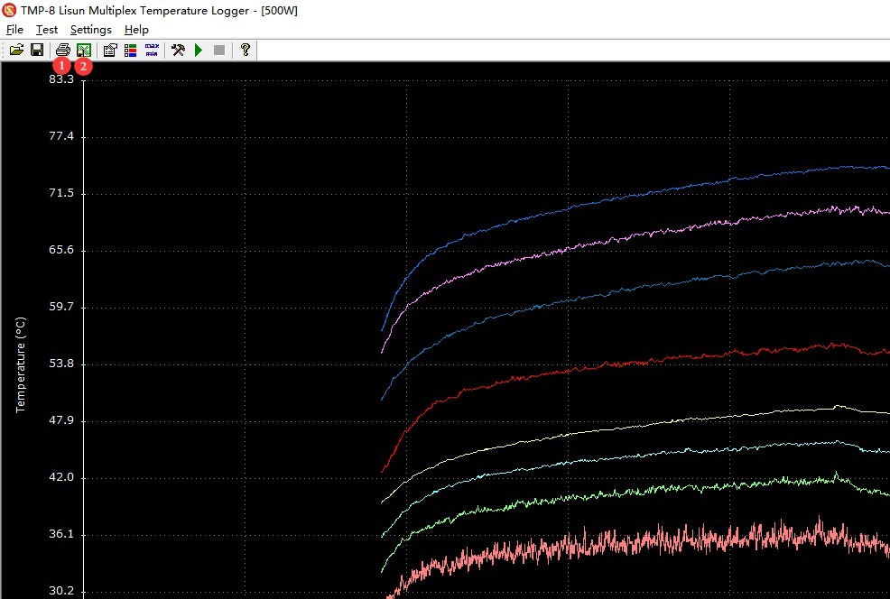
Figure 13
The printed test report is shown below.
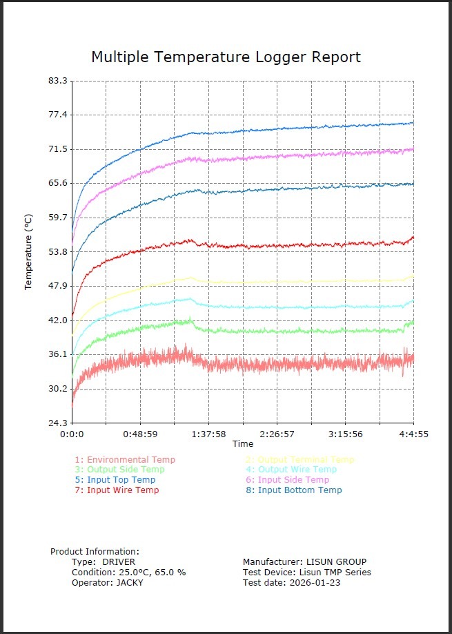
Figure 14
The exported Excel spreadsheet data is shown in the figure below.
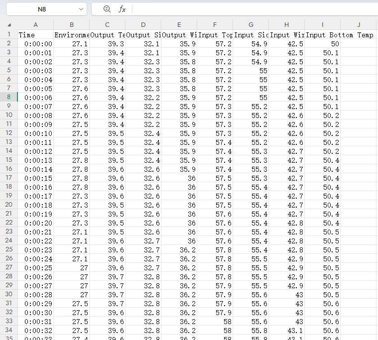
Figure 15
5. Daily Maintenance and Care of Equipment
5.1 Routine Equipment Maintenance
Wipe the instrument’s control panel and housing with a dry, soft cloth to remove dust and grease; avoid using corrosive or solvent-based cleaners such as acetone;
Clean the thermocouple plug and the instrument socket to remove any surface oxidation (you can gently wipe them with a dry cloth) to ensure good contact.
5.2 Long-Term Storage and Maintenance (When Not in Use for More Than 1 Month)
Turn off the instrument’s power, unplug all connecting cables, and cover the instrument with a dust-proof cloth to prevent dust buildup;
Select a dry, well-ventilated area free of corrosive gases, with an ambient temperature of 0–30°C and a relative humidity of ≤60%;
Organize accessories such as thermocouples, communication cables, and power cords, and store them in separate packages to prevent them from being crushed or tangled;
Power on the instrument once a month for 30 minutes to ensure that its electronic components are functioning properly.
6. Troubleshooting and Resolving Common Problems
6.1 Hardware Failures
6.1.1 The instrument will not turn on
| Fault Symptoms | Possible Causes | Procedure |
| There is no response when the power switch is pressed, and the indicator light does not come on. | 1. The power cord is not plugged in securely or is damaged; 2. There is no power at the outlet; 3. The fuse has blown | 1. Unplug and replug the power cord, and check for any damage; if damaged, replace it; 2. Check whether the power outlet is live (you can test it by plugging in another appliance); 3. Turn off the power, unplug the power cord, open the fuse holder, and replace the fuse with a 0.5A spare fuse. |
6.1.2 Display Anomalies
| Fault Symptoms | Possible Causes | Procedure |
| The temperature display shows garbled characters or fluctuates erratically | 1. The thermocouple plug is inserted into the wrong channel; 2. The thermocouple wire is broken; 3. The socket is oxidized, causing poor contact | 1. Verify that the thermocouple plug matches the channel (channels 1–8 correspond to their respective sockets), then unplug and replug it; 2. Inspect the thermocouple wires; if a break is found, cut off the damaged section and short-circuit the two wires to continue using it; 3. Clean any oxidation from the socket and plug to ensure good contact. |
| A channel is not displaying during a routine temperature check of the instrument | Turn off that channel on the instrument’s user interface; 2. Turn off that channel during previous software testing | Refer to Section 3.1.1 to enable this channel; 2. The next time you use the software for testing, refer to Section 4.2.2 to enable this channel and then retest. |
6.2 Software Failures
| Fault Symptoms | Possible Causes | Procedure |
| The software displays the message “Communication failed.” | 1. The communication cable is not securely connected; 2. The driver is not installed or installation failed; 3. The software and hardware parameters do not match; | 1. Unplug and reinsert the communication cable and USB adapter to ensure a secure connection; 2. Check that the driver has been installed successfully (there should be no yellow exclamation mark in Device Manager); 3. Verify that the instrument’s address and baud rate match the software settings (default address is 32, baud rate is 9600); |