
 English
 中文简体
中文简体 English
 Русский
 Español
 Português
 Türkçe
 العربية
 Deutsch
 Polski
 Italiano
 Français
 한국어
한국어 ไทย
ไทย Tiếng Việt
 日本語
日本語





























High Precision Rotation Luminaire Goniospectroradiometer
User's Manual
Applicable LISUN models: LSG-1890BCCD
1. Unboxing and Basic Familiarization with the Equipment
1.1 Unboxing and Inspection
When unpacking the device, handle it gently to avoid scratching the casing with sharp tools. After unpacking, first inspect the exterior of the device to ensure there is no visible deformation or dents, and that the buttons are not damaged or loose. If you notice any abnormalities with the device or its accessories, do not turn it on. Please contact us immediately.
1.2 System Configuration and Overview
1.2.1 Core Hardware Components
Note: The table below lists the core hardware components of the entire system. The equipment you purchased may include only some of these components; please keep this in mind when following the instructions in this manual.
| Component Name | Model/Specifications | Core Features |
| Goniophotomoeter Main Unit | LSG-1890B | Used in conjunction with photometric probes and Spectroradiometers to measure photometric parameters and their spatial distribution, as well as colorimetric parameters and their spatial distribution. |
| Spectroradiometer | LMS-9000CG | Used to test colorimetric parameters and their spatial distribution, such as color temperature and spatial color distribution |
| Near-field photometric probe | PM400C (N) | Suitable for standard darkrooms, such as those around 10 meters in length |
| Far-field photometric probe | PM400C (F) | Optional. Suitable for extra-long darkrooms, such as those longer than 20 meters. |
| Standard Light | SLS-150W | Used for calibrating darkrooms; includes a photometric probe and a Spectroradiometer |
| E27 Fixture | / | For C-Gamma testing; suitable for incandescent bulbs |
| Cross Clamp | For C-Gamma testing; suitable for other indoor and outdoor lighting fixtures | |
| Square Clamp | For B-Beta testing; suitable for floodlights | |
| Cross-Line Laser | Used during installation and commissioning; used during calibration and testing to determine the position and orientation of the reference lamp and the sample luminaire. | |
| Cabinet | CASE-19 | Used to house an angle controller, a power meter, and DC and AC power supplies. Includes a power distribution panel, an RS-485 communication module, and other components. |
| Angle Controller | RT-200C | The angle at which the Goniophotomoeter is positioned for display and control. Generally, no manual adjustment is required; control is handled by the software. |
| Power Meter | LS Series | Measure electrical parameters of the sample, such as voltage, current, power, and power factor |
| DC Power Supply | DC Series | Provides a stable DC power supply for DC samples, standard lamps, and auxiliary lamps |
| AC Power | LSP Series | Provides a stable, pure sine-wave AC power supply for AC samples |
1.2.2 Software, manuals, certificates, etc.
At the time of shipment, a download link containing all the documents was sent via email. Please download them as soon as possible. If you missed the email, you can contact us to request a new download link.
Includes software, user manuals, warranty cards, standard lamp calibration certificates, and other important documents, as well as other relevant documents.
1.3 Measurement Parameters
Illuminance data, illuminance distribution, area luminous flux, luminaire efficiency, luminance distribution (optional), utilization factor, luminance limit curve, glare rating, isophote curves, maximum allowable height-to-distance ratio, luminaire curve vs. illumination area, isointensity curves, effective beam angle, EEI, UGR, CCT, CRI, TM-30-24, Spectrum, (x, y)/(u, v), PAR, PPF, and PPFD spatial distribution tests, etc.
2. Important Notes
2.1 Electrical Safety
The system must be connected to a stable AC power source of 220 V ±5%, with a frequency of 50 Hz or 60 Hz, and ensure proper grounding with a grounding resistance of ≤4 Ω. Do not use the equipment if the power connections are loose or the cables are damaged.
2.2 Environmental Safety
When using the optical darkroom, the ambient temperature must be maintained at 25±1°C, and the relative humidity must be maintained between 10% and 65% RH;
Both the control room and the darkroom must be kept dry, well-ventilated, dust-free, and free of corrosive gases;
Avoid placing the device near strong magnetic or electric fields; it must be placed on a flat, sturdy surface.
2.3 Darkroom Operating Procedures
2.3.1 Darkroom Description
Please confirm that the darkroom has been constructed strictly in accordance with the darkroom drawings we provided. If there are any discrepancies in the actual dimensions, please notify us before installing and commissioning the equipment so that we can adjust the plan to ensure that installation and commissioning proceed smoothly and that test results are accurate;
The interior of the darkroom must be completely painted matte black—that is, a non-reflective pure black—including all walls, ceilings, floors, partitions, doors, and so on. A small number of components, such as lighting fixtures, air conditioning units, and power switches, may not be painted black, provided they do not appear in the optical path between the Goniophotomoeter and the photometer probe;
Once the equipment has been installed and commissioned, please do not move any of the hardware components inside the darkroom, including the main unit base, the luminance probe base, the luminance probe orientation, and the cross-laser base, as this may result in inaccurate test results.
2.3.2 Precautions for Using the Darkroom
Remove your shoes or put on shoe covers when entering the darkroom to prevent dust from being brought in;
The sample luminaires must be securely mounted to prevent them from falling and damaging the Goniophotomoeter during testing;
Do not place any objects on the Goniophotomoeter unit or within the Goniophotomoeter’s rotation range;
During testing, the darkroom must remain sealed to prevent external light from interfering with the test results.
2.3.3 Precautions When the Darkroom Is Not in Use
Keep the darkroom closed; unauthorized persons are not allowed to enter; prevent dust from entering the darkroom.
2.4 Standard Lamp Operating Procedures
The standard lamp has a service life of 1 year and is used for calibrating darkroom equipment (photometric probes, spectrometers) during installation and commissioning;
If your laboratory is required to calibrate its darkroom annually, you may purchase a new standard lamp;
The standard lamp is hot immediately after use; do not touch it. Allow it to cool for 10 minutes before returning it to the lamp case;
The standard lamp used in the darkroom is a directional standard lamp; its direction is controlled by its holder. Do not remove the bulb from its holder, or the standard lamp will become invalid.
2.5 Optical Fiber Operating Procedures
Optical Fiber must not be bent excessively (bending radius ≥ 10 cm). Do not step on or squeeze the Optical Fiber, as this may cause damage and result in abnormal test results.
2.6 Other
For matters not covered in this manual, please proceed with caution or contact us.
3. Hardware Assembly
3.1 Cabinet Equipment Assembly
3.1.1 Introduction to the Cabinet
Place the cabinet on a level, sturdy workbench, leaving sufficient space for operation.
| Number | Note |
| ① | Wiring Diagram: Please assemble the equipment according to the wiring diagram. |
| ② | Power distribution panel, used to connect the power cords of all devices inside the cabinet |
| ③ | Cooling fan power cord: Please connect it to the power strip inside the cabinet. |
| ④ | RS-485 communication box, used to connect the RS-485 communication cables of all devices |
| ⑤ | Please connect the power adapter for the RS485 communication box to the power strip inside the cabinet. |
| ⑥ | The USB cable for the RS485 communication box needs to be connected to the computer. |
| ⑦ | RT-200C Angle Controller Wiring |
| ⑧ | LS Series Power Meter Wiring |
| ⑨ | DC Power Connection |
| ⑩ | AC Power Wiring |
| ⑪ | The main power cable for the cabinet, which supplies power to all equipment inside the cabinet, should be routed out through cable opening ② and connected to the power source only after all equipment has been fully installed. |
| ⑫ | Cable opening—the main power cord can be routed through here. Note: The main power cord plug is a Chinese standard plug; you may need to use a power adapter. |
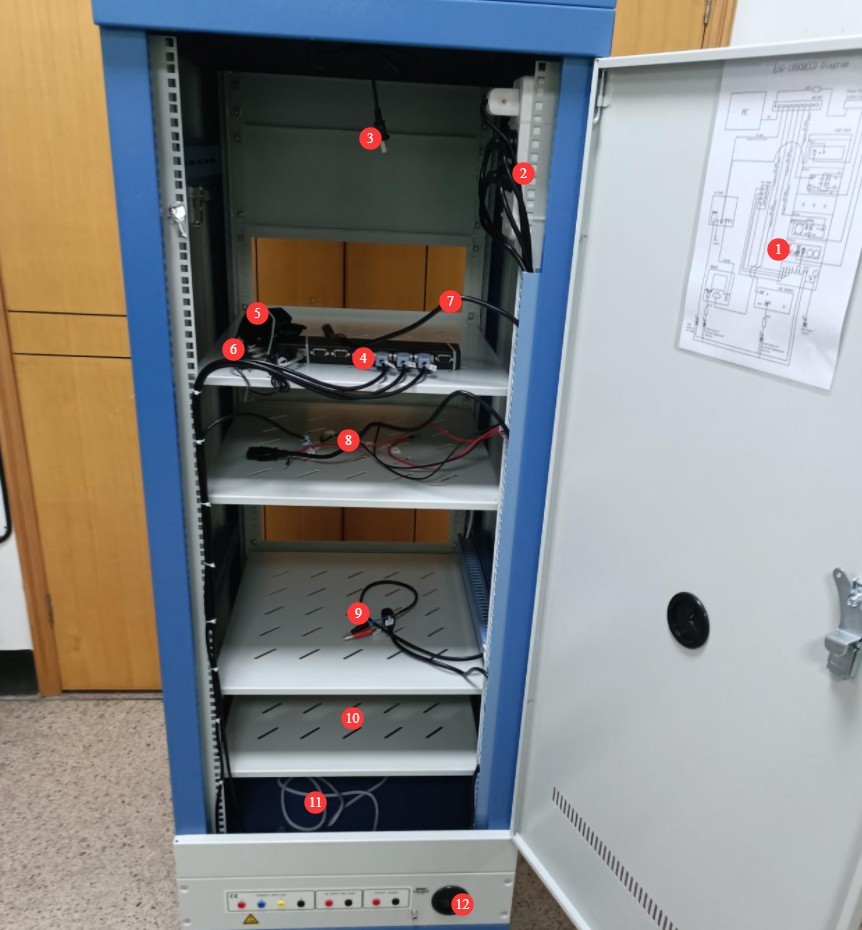
Figure 1
3.1.2 Installing the RT-200C
For now, all you need to do is plug it in.
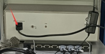
Figure 2
3.1.3 Installation of the LS Power Meter
| Number | Note |
| ① | Connected via an RS-485 communication cable; the other end is already connected to the RS-485 communication box inside the cabinet. |
| ② | The power cord is connected; the other end is already connected to the power distribution panel inside the cabinet. |
| ③ | V1 test lead, connected to the red terminal of the power meter’s V voltage |
| ④ | V2 test lead, connected to the black terminal of the power meter’s V terminal |
| ⑤ | A1 test lead, connected to the red terminal of the power meter’s current A |
| ⑥ | A2 test lead, connected to the black terminal for current A on the power meter |
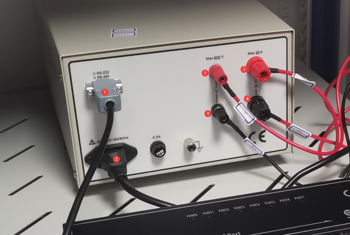
Figure 3
3.1.4 DC Power Supply Installation
| Number | Note |
| ① | Connected via an RS-485 communication cable; the other end is already connected to the RS-485 communication box inside the cabinet. |
| ② | Connect the DC power output wires, making sure to match the positive and negative terminals. |
| ③ | The power cord is connected; the other end is already connected to the power strip inside the cabinet. |
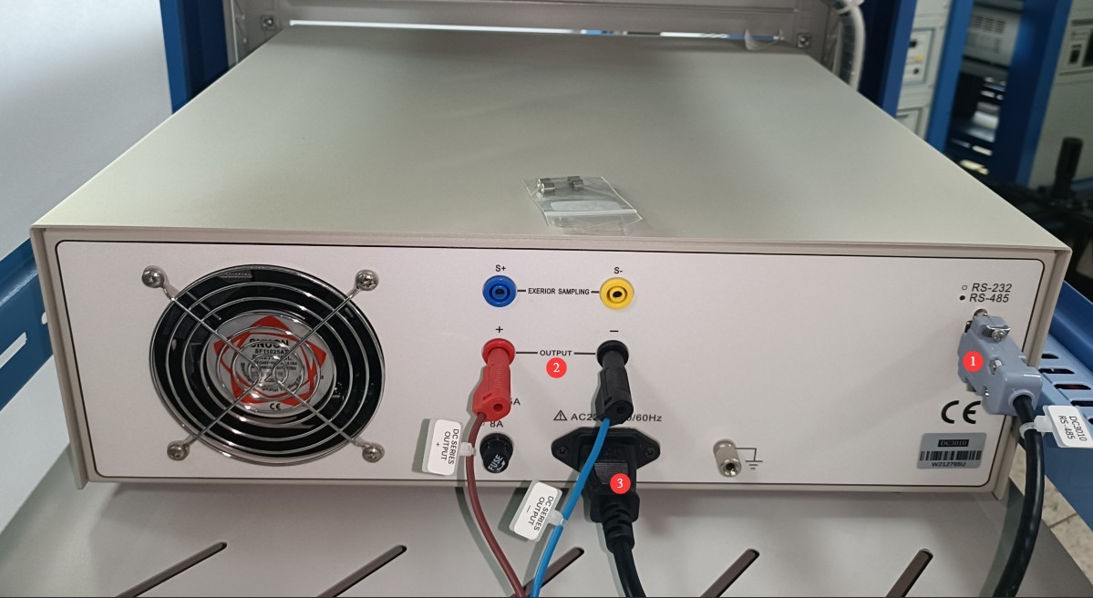
Figure 4
3.1.5 AC Power Installation
Please locate the following AC power output cable among the accessories:
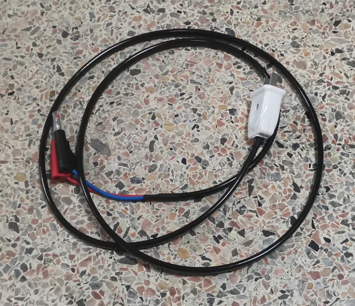
Figure 5
| Number | Note |
| ① | Connected via an RS-485 communication cable; the other end is already connected to the RS-485 communication box inside the cabinet. |
| ② | The power cord is connected; the other end is already connected to the power strip inside the cabinet. |
| ③ | Run the AC power output cord through cable opening ④ and connect it to position ⑤. |
| ④ | Wire hole |
| ⑤ | AC power output cable: Pass it through cable opening ④ and connect it to position ③. |
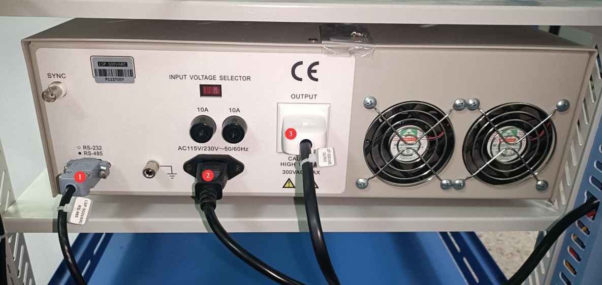
Figure 6
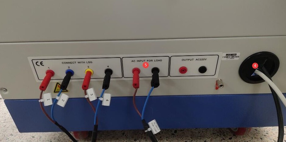
Figure 7
3.2 Installation of The Goniophotomoeter Main Unit and Goniophotomoeter Probe
3.2.1 Host Assembly
The same number is engraved on the main unit’s base tapered sleeve ① and the corresponding position on the main unit ②. Rotate the tapered sleeve until the two numbers are aligned, then secure the tapered sleeve using the hex screws provided as standard.
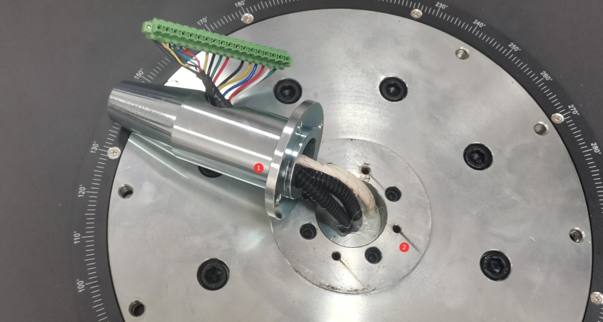
Figure 8
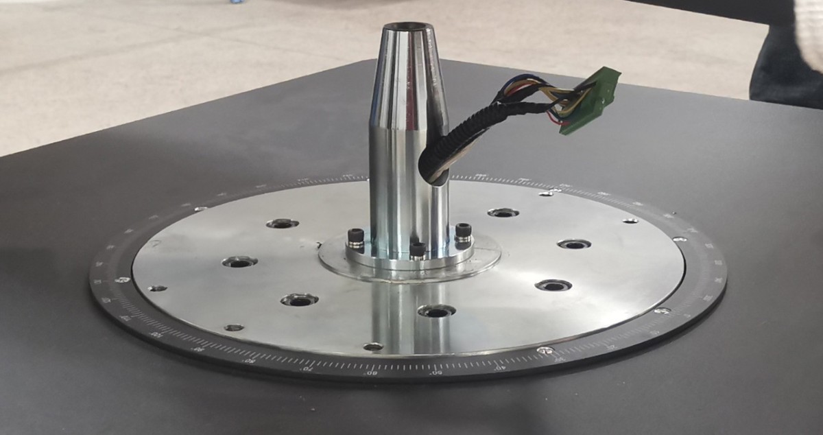
Figure 9
Remove the screws securing the dust cover on the turntable and pull the dust cover off.
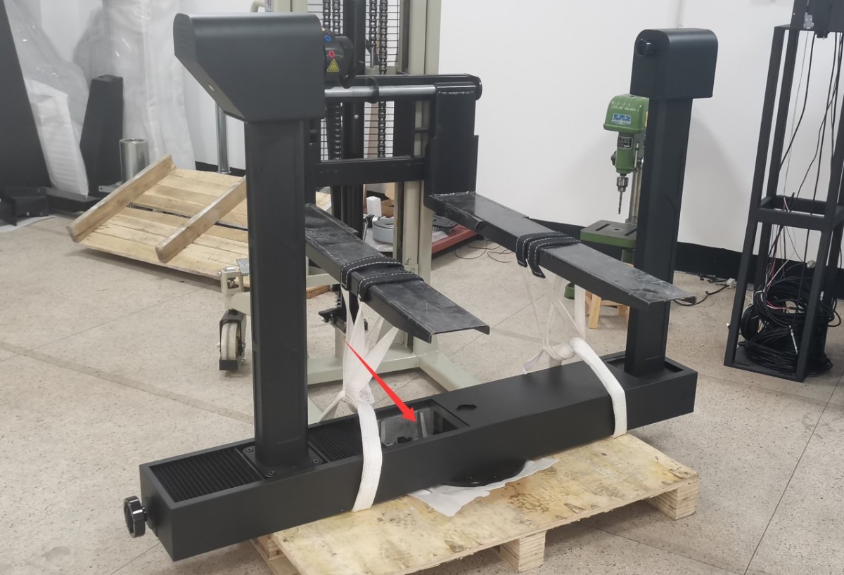
Figure 10
Use a forklift to lift the turntable. Since the turntable is quite heavy, three to four people may also carefully lift it. Align the dust cover on the turntable with the terminal block on the base, then slowly lower the turntable onto the base. Hold the terminal block in place with your hand so that it slides into the turntable along with the tapered sleeve, preventing the terminal block from being crushed by the turntable.
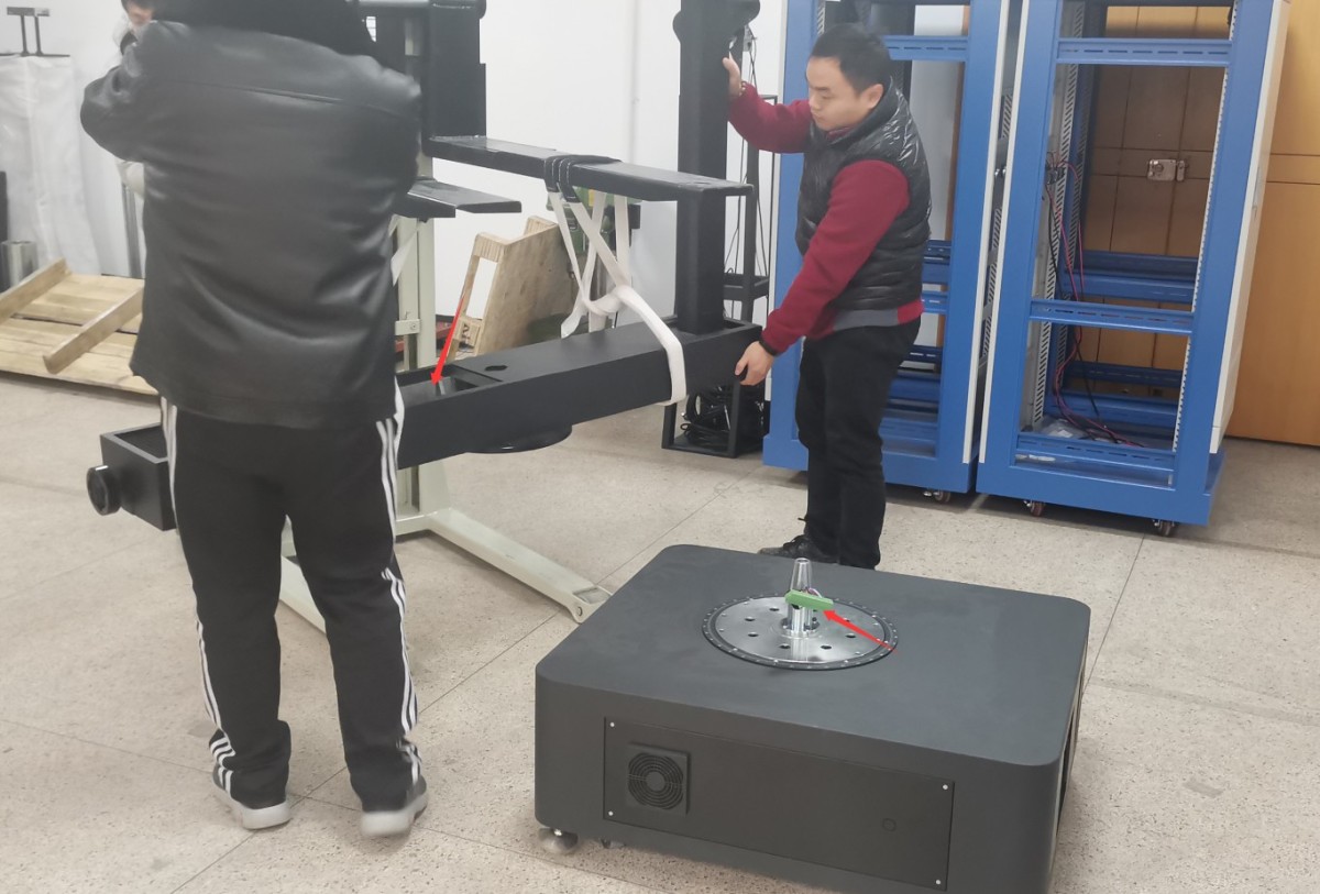
Figure 11
To fine-tune the turntable’s direction, follow these steps in the order listed below.
| Number | Note |
| ① | Align the six screw holes on the turntable with the six screw holes on the base, and use the standard hex screws and washers provided to secure the turntable to the base . Note: Be sure to use all the standard washers; otherwise, the screws may not fit properly, which could damage the equipment during turntable rotation. |
| ② | Plug the base terminal block into the corresponding terminal block socket on the turntable. |
| ③ | Then put the dust cover back in place. |
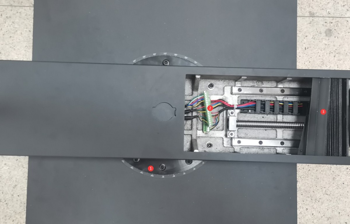
Figure 12
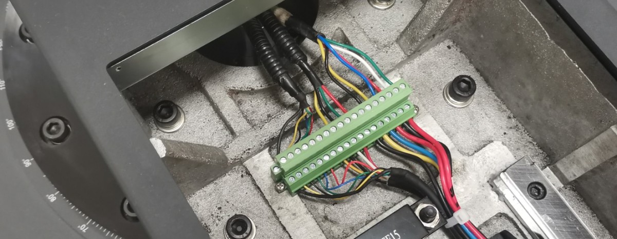
Figure 13
The four feet on the bottom of the unit are height-adjustable.
| Number | Note |
| ① | Turn the bottom screw to raise the leg until it is off the ground. |
| ② | At the same time, make sure the top screw isn’t pressing against anything; you can unscrew it slightly. |
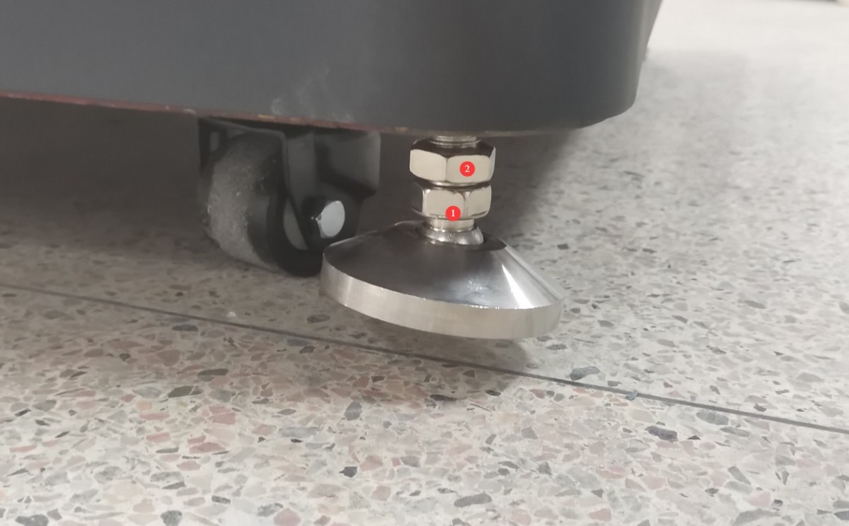
Figure 14
Position the goniophotomoeter in the correct location according to the darkroom blueprints. Align the four sides of the base as closely as possible with the walls of the darkroom. Then remove the auxiliary arm.
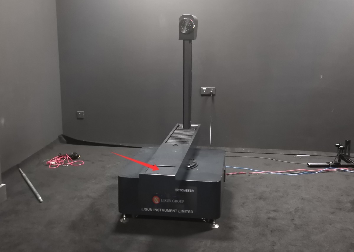
Figure 15
Next, please turn all four legs of the Goniophotomoeter until they are in contact with the floor.
3.2.2 Assembly of the Photometric Probe and Probe Holder
Take, for example, a darkroom with only one photometer.
Assemble the photometric probe and the probe bracket, and position them in the appropriate locations according to the darkroom drawings; there is no need to secure them with screws for now.
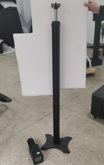
Figure 16
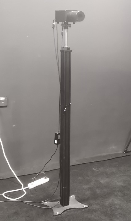
Figure 17
3.2.3 System Wiring
| Number | Note |
| ① | The four terminal blocks ①at the cabinet are connected to the Goniophotomoeter⑩; simply match them one-to-one according to the numbers. |
| ② | The two terminals are connected to the terminal block inside the cabinet and are used to supply power to all equipment in the darkroom, including the Goniophotomoeter , luminance probe, and spectroradiometer. This makes it convenient to control all darkroom equipment using the cabinet’s power switch. Note: The darkroom equipment can also be powered directly from the mains. |
| ③ | Cabinet grounding terminal: Please connect it to ground using a wire. |
| ④ | Cabinet power cord, connected to a 220V, 50/60 Hz power source |
| ⑤ | Power Cord for the Main Unit of the Goniophotomoeter |
| ⑥ | Connect the ground terminal of the Goniophotomoeter to the ground using a wire. |
| ⑦ | This is a one-to-two communication cable; one end of the RS-485 cable connects to the RS-485 communication box inside the cabinet, and the other end connects to position ⑭ on the back of the RT-200C. |
| ⑧ | Photometer probe trigger wire; connect to probe ⑬. When only one probe is installed, the default setting is near-field (N). |
| ⑨ | If you have only one photometer in your darkroom, then the far-field (F) does not need to be connected. |
| ⑩ | The four terminal blocks ⑩on the Goniophotomoeter connect to the cabinet①; simply match them one-to-one according to the numbers. |
| ⑪ | Power Adapter for Photometric Probe |
| ⑫ | RS-485 communication cable for the photometric probe; the other end connects to the RS-485 communication box inside the cabinet |
| ⑬ | Photometric probe trigger cable, connected to the main unit ⑧of the Goniophotomoeter |
| ⑭ | RT-200C communication cable, with the other end connected to the main⑦ unit of the Goniophotomoeter |
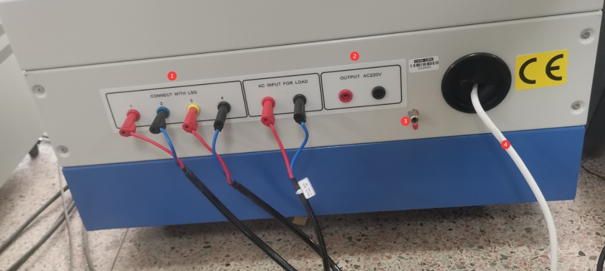
Figure 18
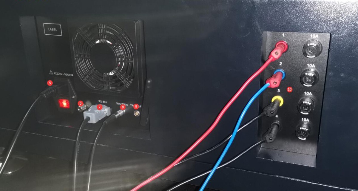
Figure 19
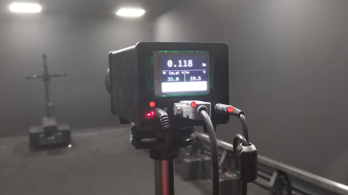
Figure 20
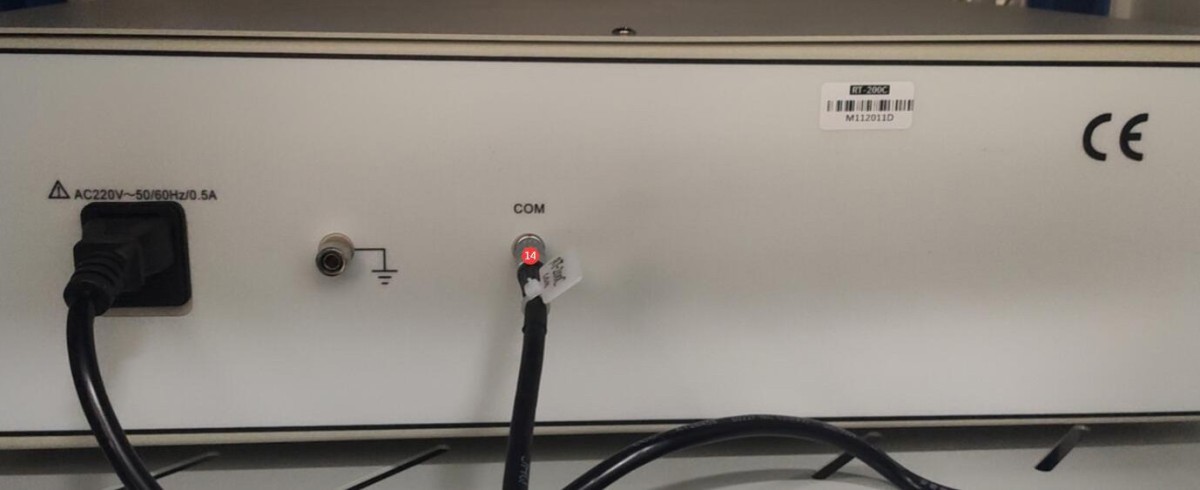
Figure 21
3.3 Installation of The Spectroradiometer
3.3.1 Assembly of The Spectroradiometer and Mounting Bracket
Assemble the spectroradiometer and the mount as shown in the figure below.
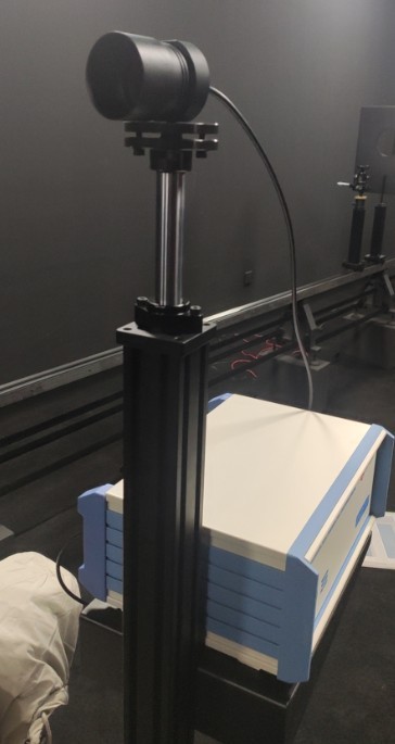
Figure 22
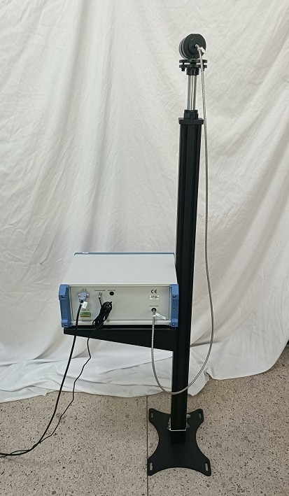
Figure 23
Place it in the appropriate position according to the darkroom drawings. For convenience, the drawing below shows the LSG-9000CG Spectroradiometer circled.
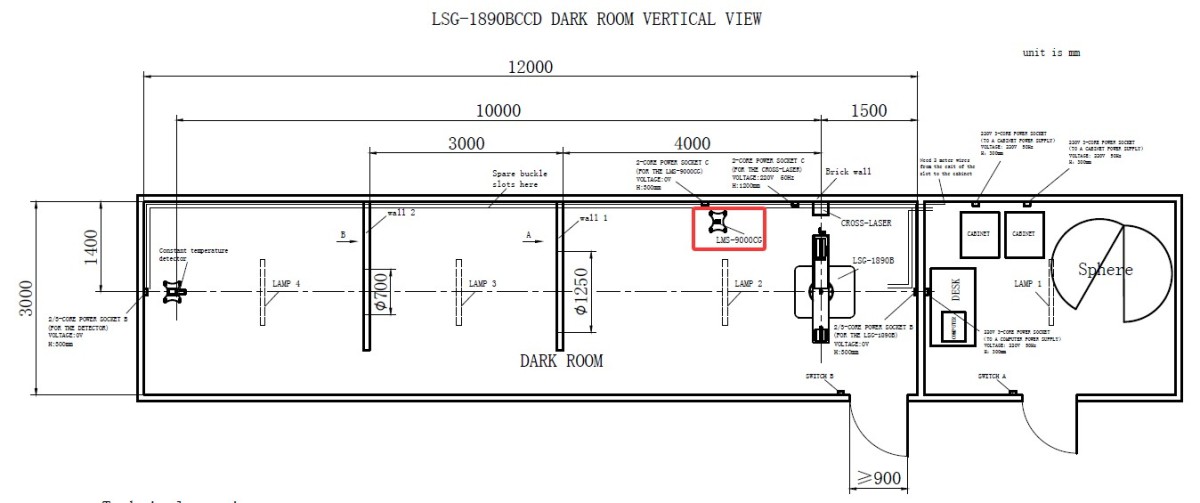
Figure 23.1
Principles for positioning the spectroradiometer: Place it as close to the wall as possible without obstructing the optical path of the photometric probe; place it as close to the main unit of the goniophotomoeter as possible to obtain more accurate colorimetric parameters; ensure that the goniophotomoeter does not come into contact with the spectroradiometer or its mount when rotating.
Then simply secure the base to the floor with screws.
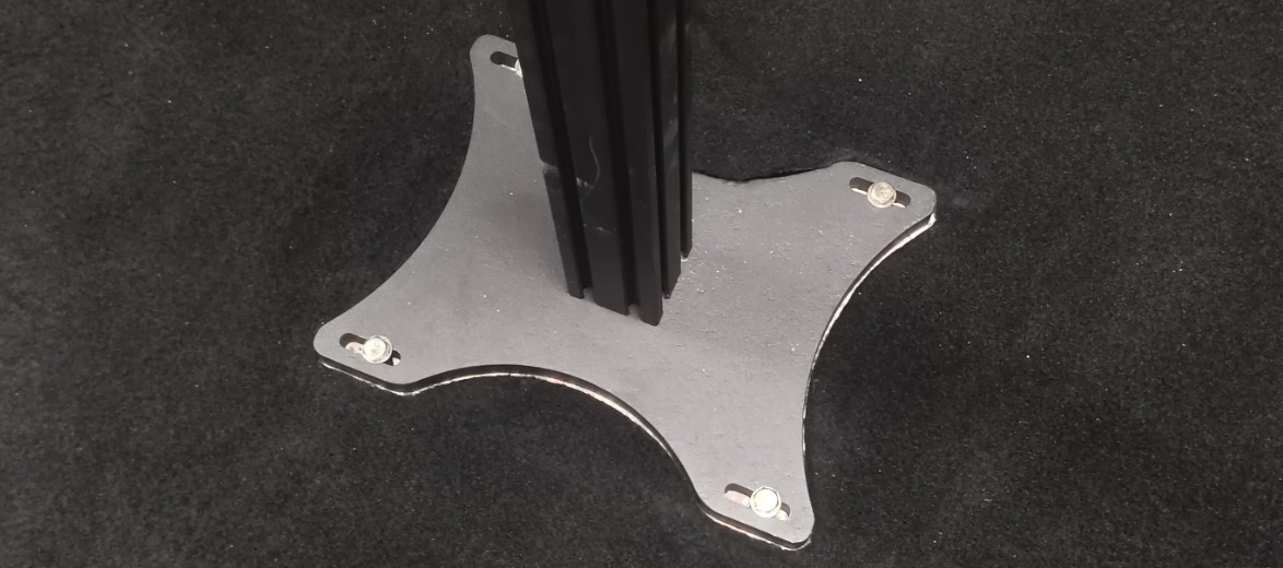
Figure 48
3.3.2 Spectroradiometer Wiring
| Number | Note |
| ① | RS-485 communication cable, with the other end connected to the RS-485 communication box inside the cabinet |
| ② | Power Adapter |
| ③ | Optical Fiber |
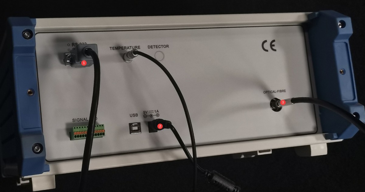
Figure 24
3.3.3 Optical Fiber Mounting
The other end of the Optical Fiber has a black ferrule; make sure the ferrule is securely tightened.
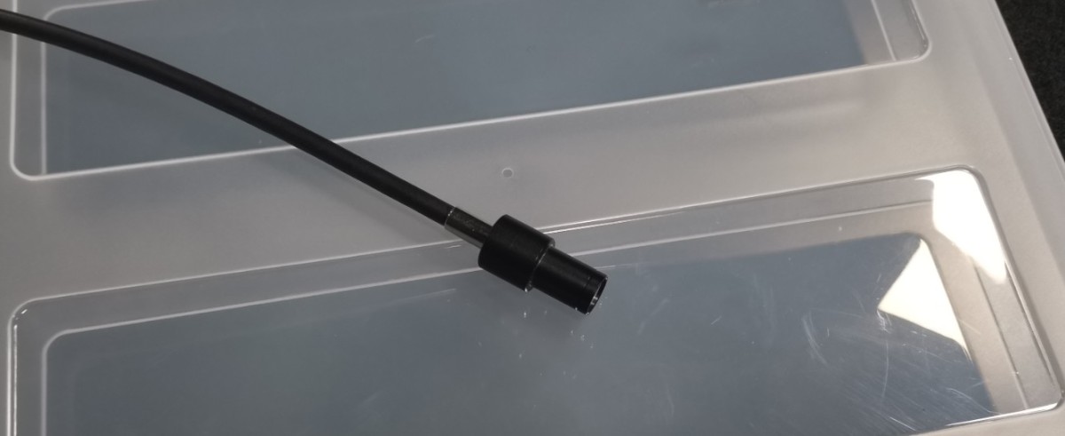
Figure 25
Secure the sleeve end to the Optical Fiber bracket and fasten it with screws.
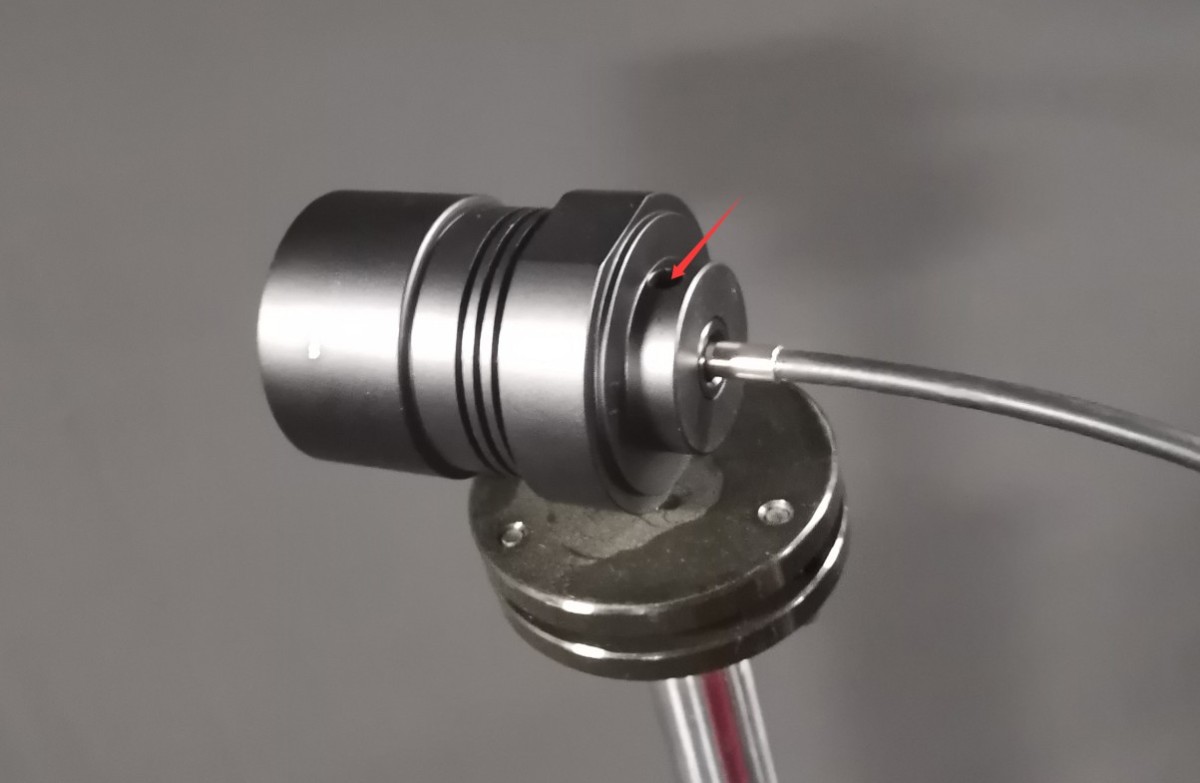
Figure 26
4. Software Installation and Configuration
4.1 Software and Driver Installation
4.1.1 Software Runtime Environment
System Requirements: Windows 7/8/10/11 (32-bit/64-bit); the computer must have at least one USB port.
4.1.2 Installation
| Number | Note |
| ① | LSG Series Goniophotomoeter Software—please double-click to install |
| ② | This APK file can be copied to an Android phone for installation. The app is intended solely for rotating the Goniophotomoeter and cannot be used for testing. Since the software fully incorporates the app’s functionality, this manual uses the software as an example for operation. |
| ③ | RS485 Communication Box Driver—Double-click to install |
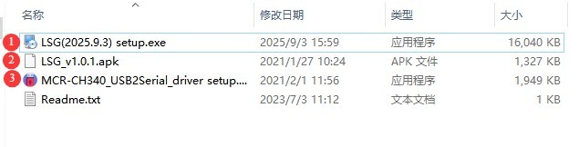
Figure 27
4.1.3 Exception Handling
If your antivirus software or Windows Firewall flags a file as suspicious during the software installation process, please temporarily disable the antivirus software or Windows Firewall and then try installing the software again.
If the software fails to open when you double-click the icon after a successful installation, please check whether you are logged in to your computer with an administrator account. If the software still does not open after logging in with an administrator account, right-click the software icon to open its Properties window. On the Compatibility tab, check the box next to “Run this program as an administrator,” click “Apply,” and then double-click the icon again to open the software.
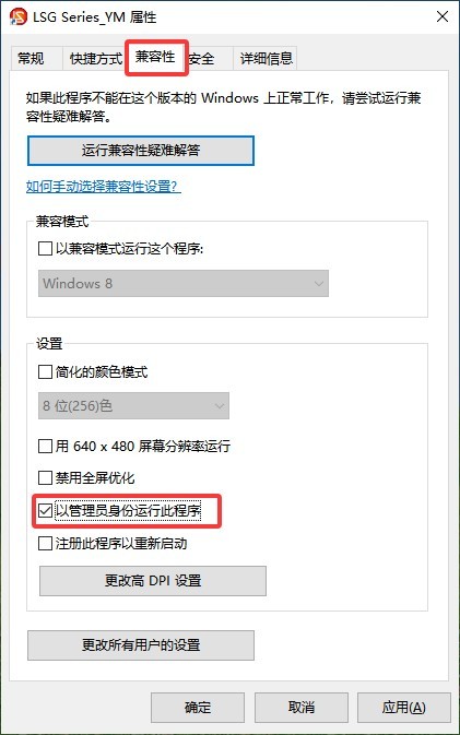
Figure 28
4.2 Software Settings
First, turn on the cabinet power switch, then power on all system devices, including all equipment inside the cabinet, the Goniophotomoeter main unit, the photometric probe, and the Spectroradiometer. Double-click to run the software. The first time you run the software, it will automatically open the system configuration interface. Select the correct model for each device you have purchased.
| Number | Note |
| ① | To select a goniophotomoeter model, click the drop-down list on the right. The model you purchased is the LSG-1890B. |
| ② | Near-field photometer probe; select photometer probe model PM400C |
| ③ | Far-field photometric probe; if you have not purchased one, please select “Not installed.” |
| ④ | Near-field spectroradiometer; select spectroradiometer model LMS-9000CG |
| ⑤ | AC power supply models are typically from the LSP Series |
| ⑥ | DC power supply models are generally designated as the DC Series |
| ⑦ | Power meter model: The model number is printed on the front panel of the power meter. Please check it and select the appropriate model. |
| ⑧ | Once you have selected all the correct models, click “Auto-Detect Port.” |
| ⑨ | After the search for all ports is complete, click “OK” to save and exit. |
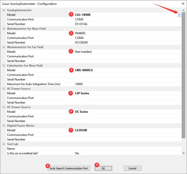
Figure 29
Note: If a communication error occurs during the automatic port search, please read the error message carefully, check whether the corresponding device is powered on, and verify that the RS-485 communication cable is properly connected. Once you have confirmed these points, click “Automatic Port Search” again until communication is established with all devices.
After clicking OK, the software automatically opens the screen for saving the database file. From then on, all test reports will be automatically saved in this database file.
| Number | Note |
| ① | Please select the path where you want to save the database file. Please do not save it to the desktop or inside the Desktop folder. |
| ② | Enter the file name |
| ③ | Just click “Save” |
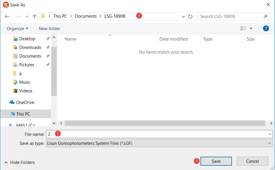
Figure 30
5. Calibration of darkroom equipment (Each step must be performed carefully and thoroughly; otherwise, it may result in incorrect calibration data and abnormal test results.)
5.1 Horizontal Commissioning of the Host Machine
5.1.1 Laser Ready
There is a laser switch on the back of the goniophotomoeter’s main arm. When you turn on the line laser switch, you will see a red line laser beam emitted directly in front of the main arm.
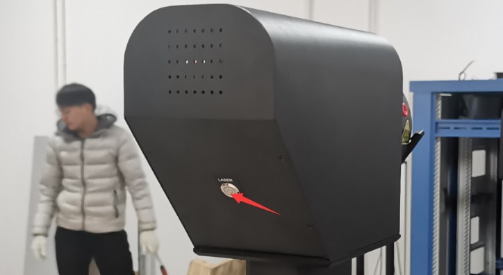
Figure 31
Find the crosshair laser device and tripod.
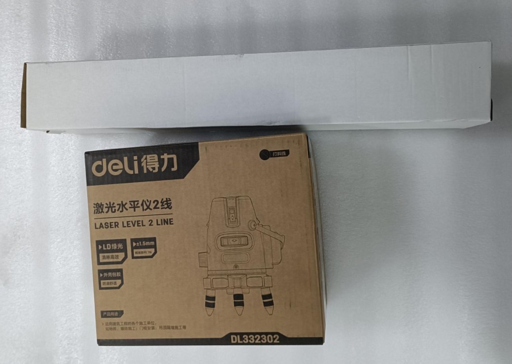
Figure 32
Remove the cross-line laser and the batteries. Insert the batteries into the cross-line laser. The power switch is located on the side of the device. Turn the switch to the “unlock” position to turn on the device.
| Number | Note |
| ① | Power switch: Move it to the “Unlock” position to turn on the power. |
| ② | VH refers to vertical and horizontal laser switches, respectively. |
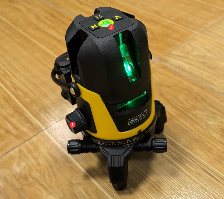
Figure 33
Mount the crosshair laser onto the tripod.
Note: The cross-line laser is self-leveling. If it is not self-leveled, an audible alarm will sound. This may be due to an uneven surface or an improperly set up tripod. Please ensure that the cross-line laser remains self-leveled at all times during use.
5.1.2 Steps for Horizontal Commissioning of the Host Machine
According to the darkroom drawings, the center height of the LSG-1890B goniophotomoeter is 1510 mm. Using a tripod, adjust the height of the horizontal laser beam to 1510 mm. At this height, the horizontal laser beam should pass through the center of all light-transmitting holes in the darkroom partition.
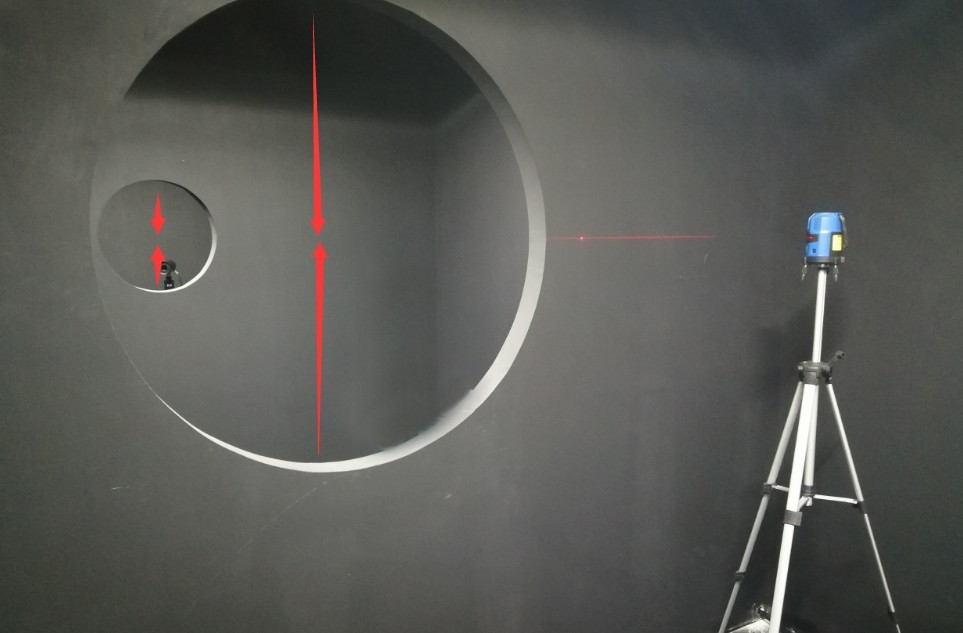
Figure 34
Please note: Do not place any objects on the Goniophotomoeter or within its rotation range to prevent damage to the equipment during rotation.
Open the software.
| Number | Note |
| ① | Click to switch angle modes |
| ② | Click ① to display the C-Gamma angle here instead of the B-Beta angle. |
| ③ | Then click to open the angle control interface |
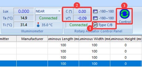
Figure 35
| Number | Note |
| ① | Gamma angle: Please select a near-field photometric probe |
| ② | Click the continuous rotation button in any direction. The gamma axis of the Goniophotomoeter will then begin to rotate continuously. |
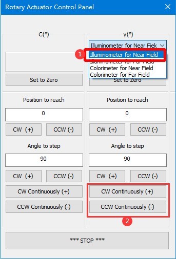
Figure 36
At this point, observe the straight laser beam emerging from the main axis of the Goniophotomoeter and the horizontal laser beam from the crosshair laser.
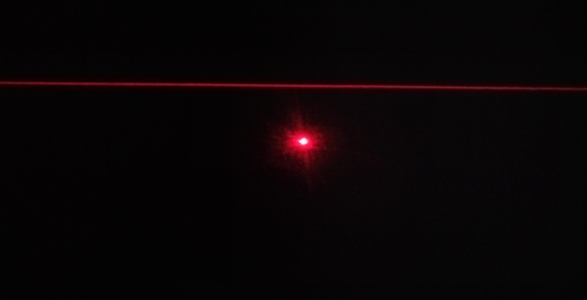
Figure 37
Then, using an appropriate wrench, raise the goniophotomoeter and adjust it to a level position by adjusting the height of its four legs. The final result of the calibration: Regardless of the Gamma angle of the goniophotomoeter, its straight laser beam is perfectly aligned with the horizontal laser beam, as shown in the figure below.
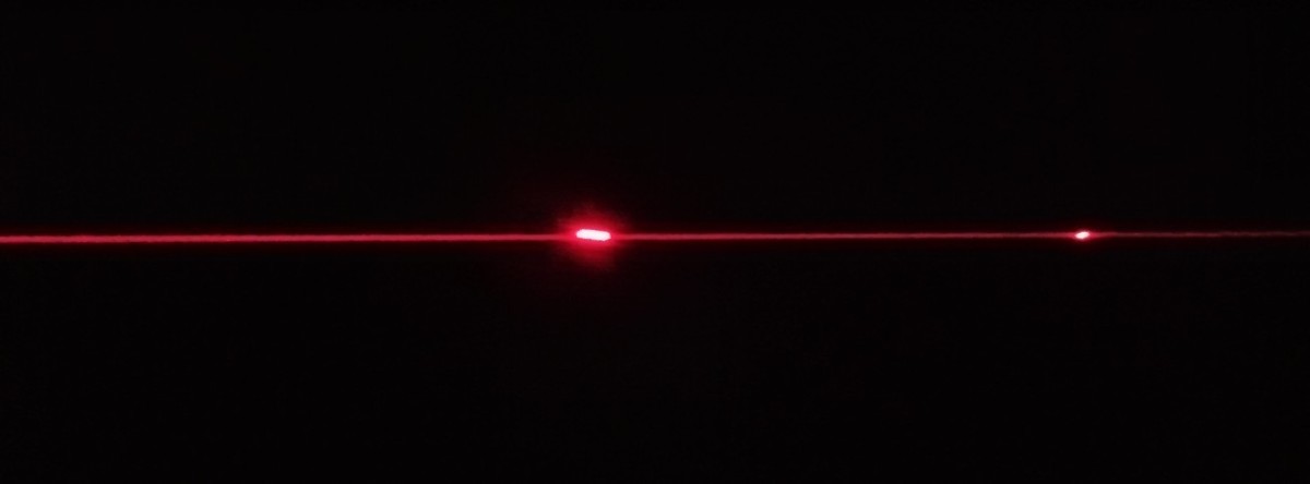
Figure 38
You’ll need plenty of patience to complete this step. Once adjusted, make sure all four legs of the main unit are firmly on the ground. You can then click the “Stop” button on the software’s angle control interface to stop the Goniophotomoeter from rotating. Next, secure the four legs of the Goniophotomoeter by tightening the screws at their tops. Once the position and level of the Goniophotomoeter unit have been properly adjusted, do not move it again, as this will cause deviations in the test results.
5.2 Calibration of the Photometric Probe
5.2.1 Calibration of the Photometric Probe at the 0-Degree Position
| Number | Note |
| ① | Still opting for a near-field photometer |
| ② | Enter 0 |
| ③ | Click any rotation direction to rotate the Gamma axis back to the 0-degree position. |

Figure 39
Verify that the single-line laser beam passes through the exact horizontal center of the last partition at this point.
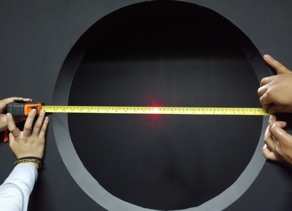
Figure 40
If not, follow the steps below.
| Number | Note |
| ① | Please enter a small angle value here based on the actual situation, such as 1, 0.1, 0.05, etc. |
| ② | Select a rotation direction and rotate the Gamma axis until the laser beam passes through the exact center of the horizontal plane of the last partition. |
| ③ | Click “Set to 0 Degrees” to set the current position of the Gamma axis on the near-field photometric probe to 0 degrees. The password is LISUNGROUP. |
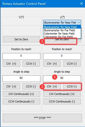
Figure 40.1
Note 1: After setting the Gamma axis of the near-field photometer to 0 degrees, do not arbitrarily set it to 0 degrees again, as this will cause deviations in the test results.
Note 2: Definition of the Gamma angle for a goniophotomoeter. The direction directly facing the photometer probe is defined as 0 degrees/360 degrees. When rotating clockwise, the angle value increases from 0 degrees to 360 degrees; when rotating counterclockwise, the angle value decreases from 360 degrees to 0 degrees. Since angle notation may vary, -90 degrees and 270 degrees refer to the same position.
5.2.2 Mounting the Photometric Probe
Rotate the light probe’s light shield counterclockwise and remove it.
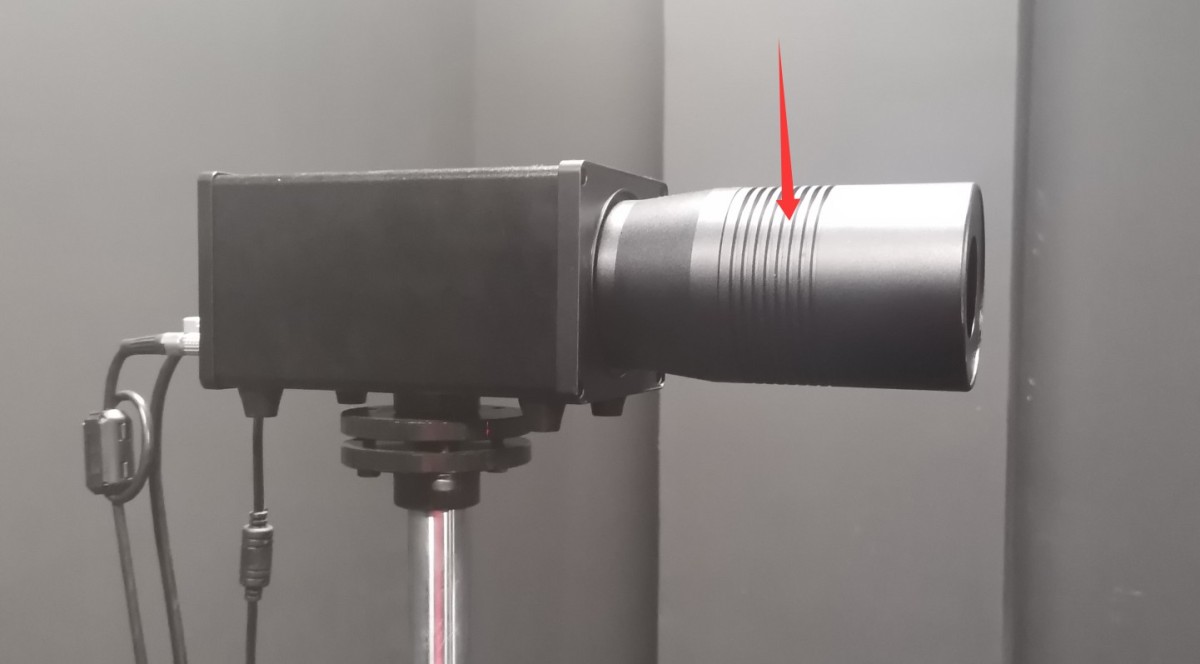
Figure 41
The standard lamp packaging box contains a small mirror.
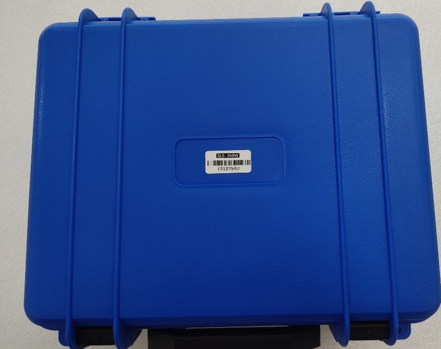
Figure 42
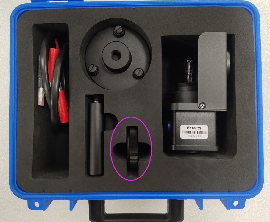
Figure 43
Remove the small reflector and attach it to the probe.
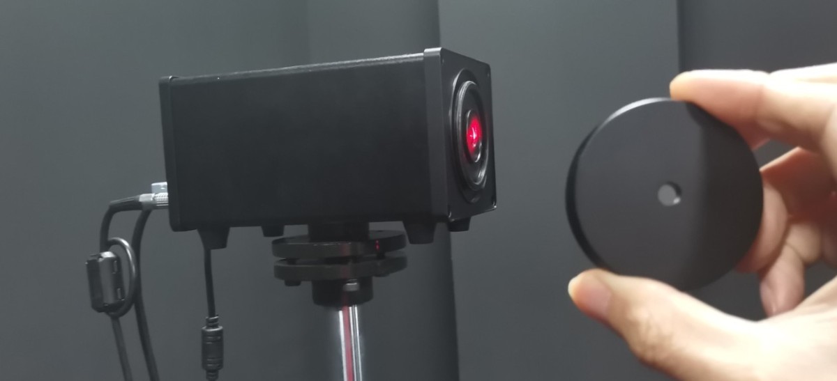
Figure 44
At this point, the Gamma axis of the near-field photometer is still at the 0-degree position. Slightly move the probe base and adjust the screws at points ① and ② to adjust the probe’s height and orientation. Position the probe so that the straight-line laser beam coming from the main axis hits the exact center of the mirror, and ensure that the reflected beam travels back along the same path.
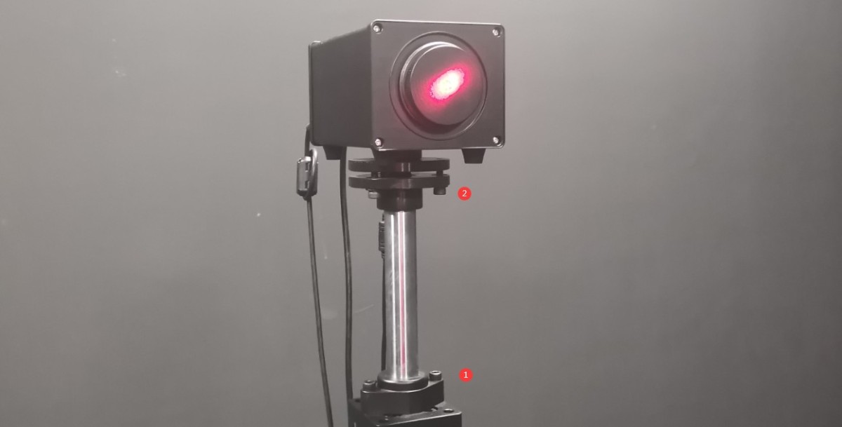
Figure 45
Then secure the probe bracket base to the floor with screws.
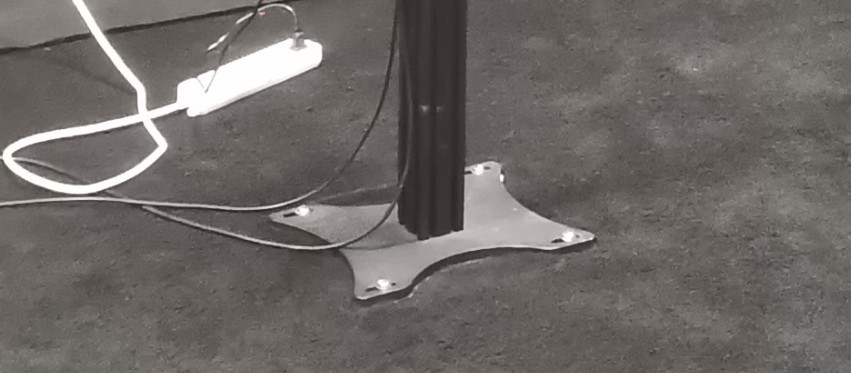
Figure 46
Once secured, you may need to make slight adjustments to the probe’s height and orientation so that the straight laser beam continues to hit the exact center of the reflector and the reflected light returns along the same path. After calibration is complete, ensure that all screws are tightened. Then remove the reflector and reinstall the light probe’s light shield.
Note: Once the probe’s position and orientation have been set, do not change them, as doing so may cause the test data to be inaccurate.
You can secure the photometer probe’s power adapter to the probe bracket as shown in the figure below to protect the probe’s power jack.
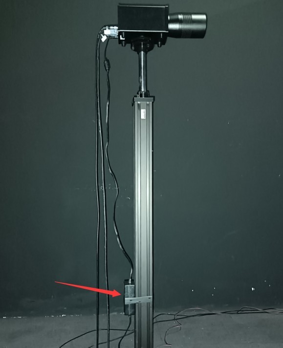
Figure 47
5.3 Calibration of the Spectroradiometer
Attach the small mirror to the Optical Fiber bracket.
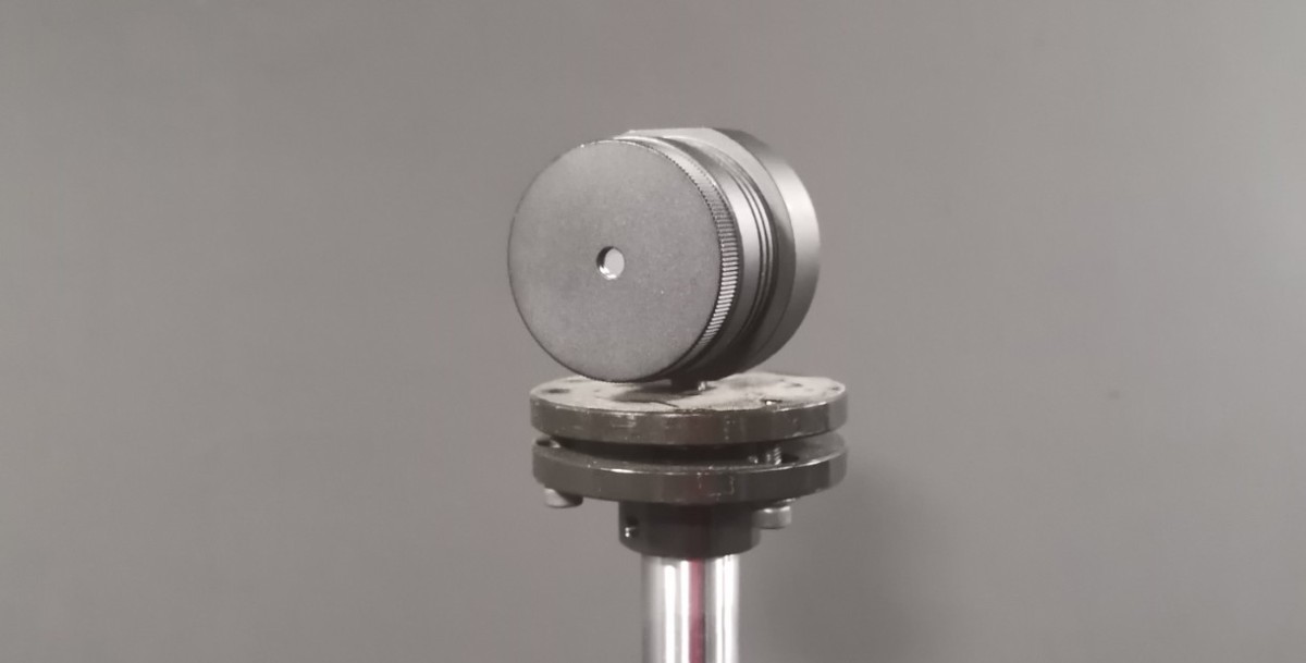
Figure 49
Software-based control interface.
| Number | Note |
| ① | Selecting a Near-Field Spectroradiometer |
| ② | Rotate the Gamma angle of the near-field Spectroradiometer until the single-line laser on the main axis is directed toward the Optical Fiber holder. |
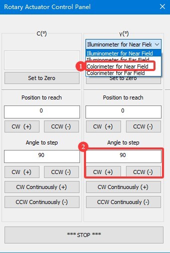
Figure 50
Slightly adjust the angle of the Gamma axis and use the screws on② the spectrometer’s Optical Fiber mount① to change the height and orientation of the small mirror so that the line laser is directed precisely at the center of the mirror and the reflected beam returns along the same path.
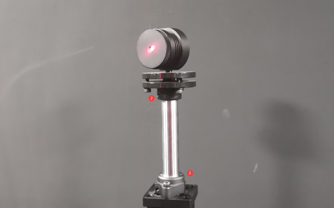
Figure 51
Once the adjustment is complete, all screws should be fully tightened. Then, click “Set 0 Degrees” on the software’s angle control interface to set the current position of the near-field Spectroradiometer’s Gamma axis to 0 degrees. The password is LISUNGROUP.
Remove the small reflector and store it safely. Reinstall the Optical Fiber bracket sleeve.
Note: After setting the Gamma axis of the near-field Spectroradiometer to 0 degrees, do not arbitrarily set it to 0 degrees again, as this will cause deviations in the test results.
5.4 Cross-Line Laser Installation
Finally, the crosshair laser must be mounted on the side wall of the darkroom. Depending on the specific layout of each darkroom, the crosshair laser can be mounted on either the left or right wall. Take the darkroom layout shown in the figure below as an example.
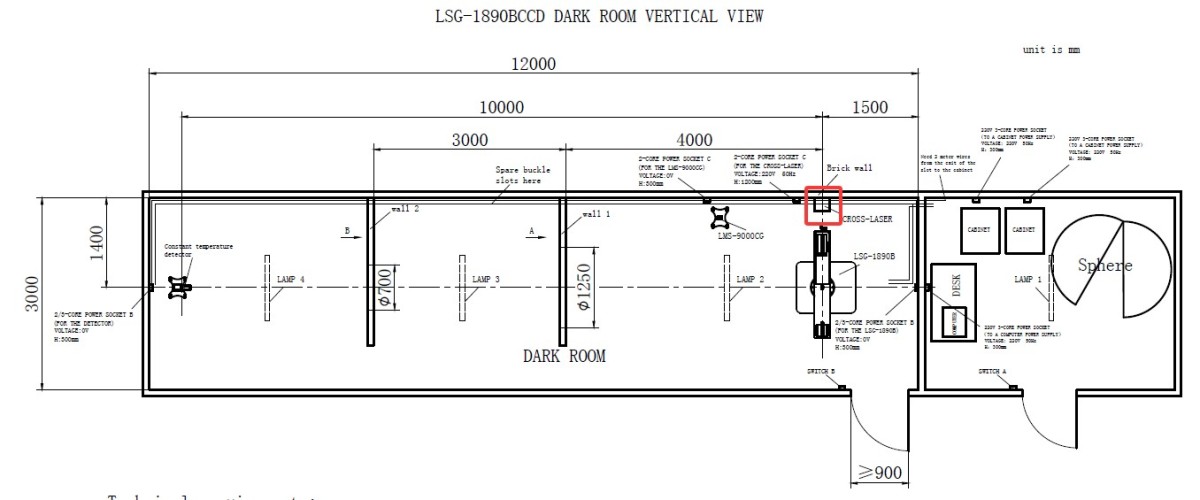
Figure 52
Go to the angle control screen.
| Number | Note |
| ① | Selecting a Near-Field Photometric Probe |
| ② | Enter 90 (if the installation position of the crosshair laser in your darkroom blueprint is different, enter -90) |
| ③ | Click to rotate the gamma axis to a 90-degree position, so that the main-axis laser beam is directly aligned with the position where the crosshair laser is installed. |
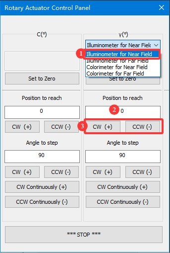
Figure 53
Secure the crosshair laser to the triangular mount we provide.
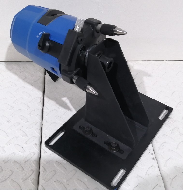
Figure 54
Turn on the crosshair laser and use the direction of the single-line laser to roughly determine the position of the crosshair laser.
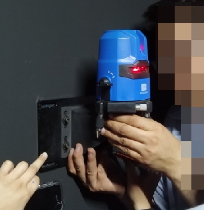
Figure 55
Fine-Tune the Position of the Crosshair Laser: Ensure that the horizontal laser beam is perfectly aligned with the centerline of the crosshair laser. You can verify and adjust the position using the following method. Place a sheet of white paper at the exit of the crosshair laser and at the exit of the single-line laser. If the centerline of the single-line laser aligns with the centerline of the crosshair laser at both locations, you can confirm that the position and orientation of the crosshair laser are correct.
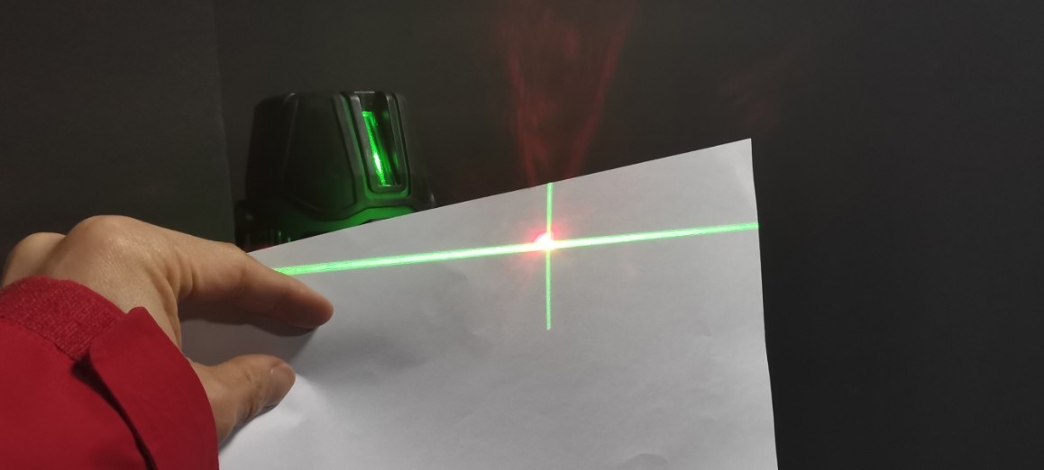
Figure 56
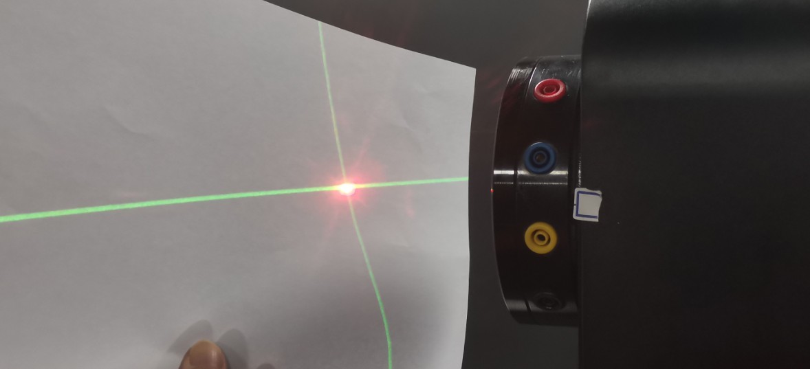
Figure 57
Next, secure the cross-laser tripod to the wall using screws. Once secured, you can still loosen the screws if necessary to make slight adjustments to the cross-laser’s position horizontally and vertically, ensuring it remains properly aligned. After calibration is complete, all screws should be tightened securely.
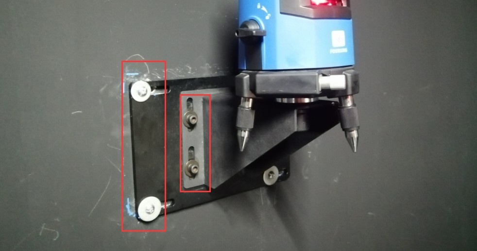
Figure 58
Then rotate the gamma axis back to the 0-degree position. The cross-shaped laser beam is projected onto the opposite wall. This creates a permanent mark. In other words, when the cross-shaped laser beam is projected in this direction, it indicates the horizontal and vertical center positions of the Goniophotomoeter. This mark is needed for both calibration and testing.
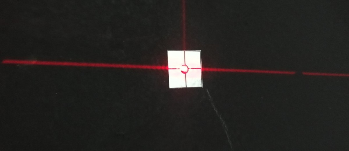
Figure 59
Installation and commissioning are complete. Turn off the line-shaped laser on the main shaft of the Goniophotomoeter.
5.5 Cleaning
You may shut down all equipment. When doing so, first turn off the power switch on each device, then turn off the main power switch for the cabinet. Next, thoroughly clean the darkroom and control room. To prevent dust from entering the equipment, cover the devices with dust-proof cloths before cleaning. After cleaning, turn all equipment back on and resume the calibration and testing procedures.
Note: Keep the darkroom as dust-free as possible while in use.
6. Calibration
6.1 Installation and Commissioning of Standard Lamps
6.1.1 Installation of Standard Lamps
First, turn on the crosshair laser on the wall and rotate it to ensure that it is aligned with the mark on the opposite wall.
Open the Standard Lamp box.
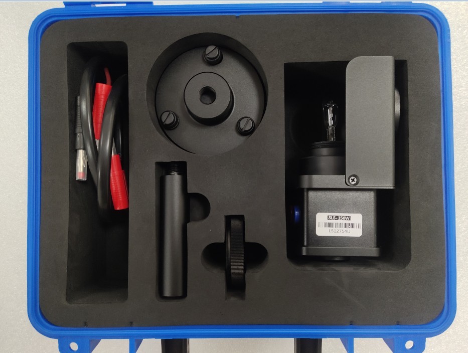
Figure 60
Then assemble the standard lamp bracket as shown in the figure below.
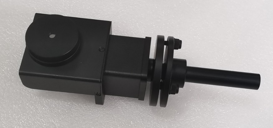
Figure 61
The main shaft of the Goniophotomoeter should still be aligned directly with the photometric probe, i.e., the probe’s 0-degree position. Locate the alignment rod, install it at the center of the Goniophotomoeter, and remove the top section.
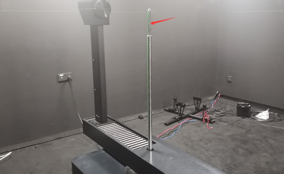
Figure 62
Please follow the instructions below to connect the wires.
| Number | Note |
| ① | The main shaft of the goniophotomoeter has four terminals for connecting the power and sampling cables of the standard lamp and sample luminaire. Use shorting wires to short-circuit the red and yellow terminals together, and the black and blue terminals together. |
| ② | Connect the power cord of the standard lamp/sample lamp to the red and blue terminals on the main shaft. |
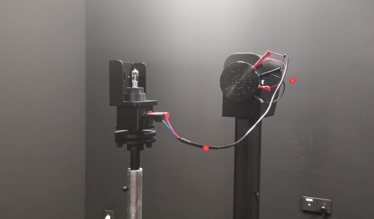
Figure 63
6.1.2 Calibration of the Standard Light Direction
| Number | Note |
| ① | Loosen the screw here to adjust the height of the standard lamp. |
| ② | There are three screws here that allow you to adjust the pitch of the standard light. |
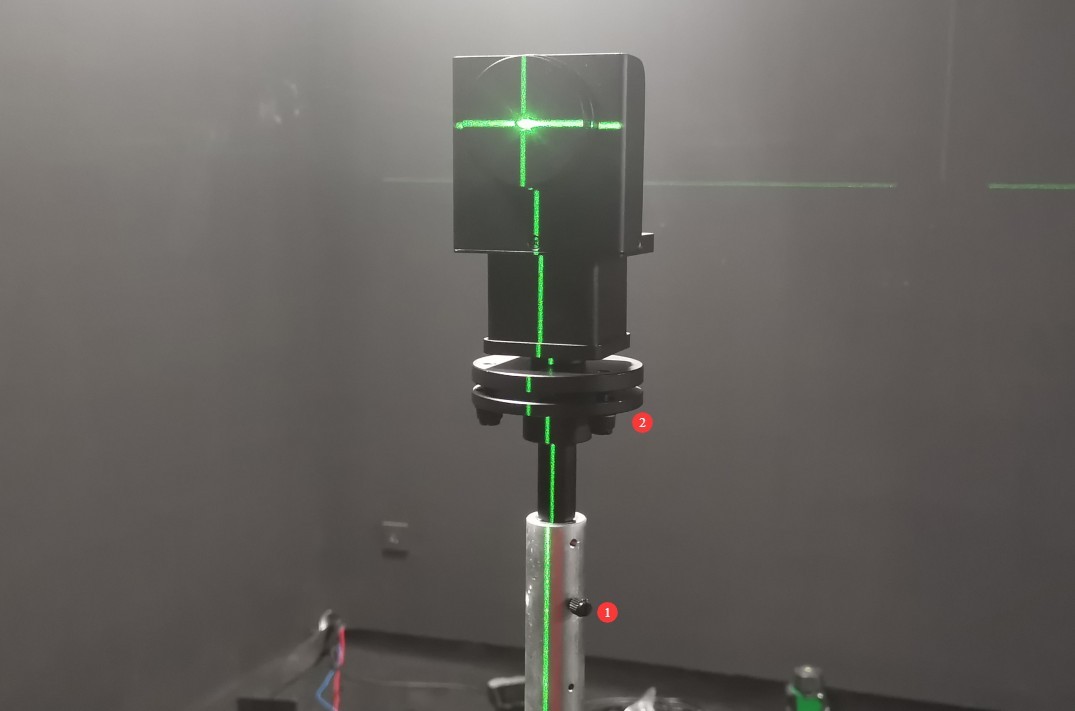
Figure 64
The standard lamp should be adjusted so that the cross-shaped laser beam is directed at the center of the small mirror, and the horizontal and vertical laser beams reflected by the mirror coincide exactly with the original cross-shaped laser beam.
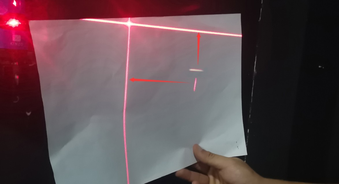
Figure 65
Based on our experience, follow these steps for calibration: First, adjust the height of the reference lamp to the appropriate position. The vertical reflected laser can be calibrated by rotating the calibration target, while the horizontal reflected laser can be calibrated by adjusting the pitch of the reference lamp. After calibration, the center height of the reference lamp may change, requiring you to readjust its height. Continue the reflection adjustment until the cross-shaped laser beam is projected onto the center of the small mirror, and the reflected horizontal and vertical laser beams are perfectly aligned with the original cross-shaped laser beam.
Once the standard lamp is properly aligned, carefully remove the small reflector, taking care not to alter the standard lamp’s alignment during removal. Then turn off the crosshair laser.
6.2 Calibration of the Photometric Probe
All standard lamps are constant-current DC light sources. Set the AC/DC switch on the 19-inch Standard Instrument Cabinet to DC.
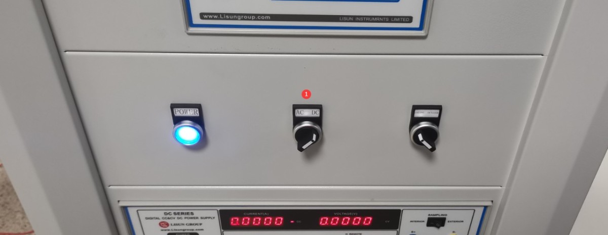
Figure 66
Open the software angle controller.
| Number | Note |
| ① | Gamma-Angle Near-Field Photometric Probe |
| ② | Enter -90 |
| ③ | Click to rotate the Gamma axis to the -90-degree position (if the crosshair laser is installed in a different position on your darkroom drawing, you will need to rotate it to the 90-degree position). |
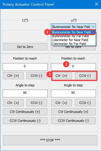
Figure 66.1
Align the circular opening in the standard lamp mount so that it faces the photometric probe.
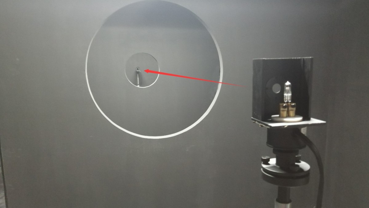
Figure 67
Turn on the calibration lamp and enter the calibration interface.
| Number | Note |
| ① | Select a DC Power Supply |
| ② | The standard lamp is a constant-current light source. Select CC (constant-current mode) and enter the reference voltage and rated current as specified in the standard lamp certificate; typically, these are 30 V and 6.1 A. |
| ③ | Click to turn on the standard lamp and turn off all other lights in the darkroom. The standard lamp takes 15 minutes to reach a steady state. |
| ④ | Once the standard lamp has stabilized, click to enter the photometer calibration interface. |
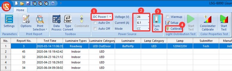
Figure 68
Close the darkroom door and make sure that all light sources in the darkroom are turned off, except for the standard lamp.
| Number | Note |
| ① | Selecting a Near-Field Photometric Probe |
| ② | Luminous flux calibration—our software includes this option, but current industry standards require the use of luminous intensity calibration, and the standard lamps included in our standard configuration are also luminous intensity standard lamps. Therefore, there is no need to use luminous flux calibration at this time. |
| ③ | Light Intensity Calibration Method |
| ④ | Refer to the standard lamp calibration certificate and enter its calibrated luminous intensity value. |
| ⑤ | Click to Start |
| ⑥ | The software will automatically calculate the test distance. |
| ⑦ | To verify the results, click “Check,” and the software will display the current measured light intensity. The measured light intensity should match the calibrated value. |
| ⑧ | Click “OK” to save and exit |
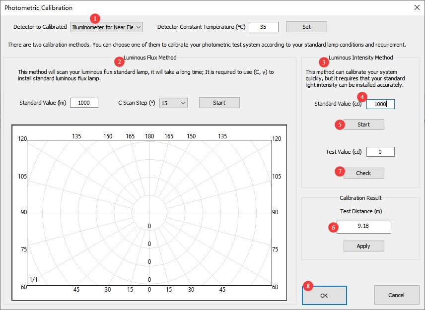
Figure 69
Note: The test distance is the distance from the center of the Goniophotomoeter to the surface of the photometric probe. The distance calculated by the software should be close to the actual distance; an error of 1% or less is considered normal. If the error is too large, please refer to Section 2.3.1 to verify that the darkroom is functioning properly, and refer to Chapter 5 to verify the calibration procedure.
6.3 Calibration of Spectroradiometers
The reference lamp remains lit and stable. Enter the angle control interface.
| Number | Note |
| ① | Gamma-Angle-Selective Near-Field Spectroradiometer |
| ② | Enter -90 |
| ③ | Click to rotate the gamma axis to the -90-degree position (if the installation position of the crosshair laser in your darkroom drawing is different, you will need to rotate it to the 90-degree position). |
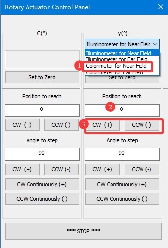
Figure 70
Align the round hole in the standard lamp mount so that it faces the photometric probe.
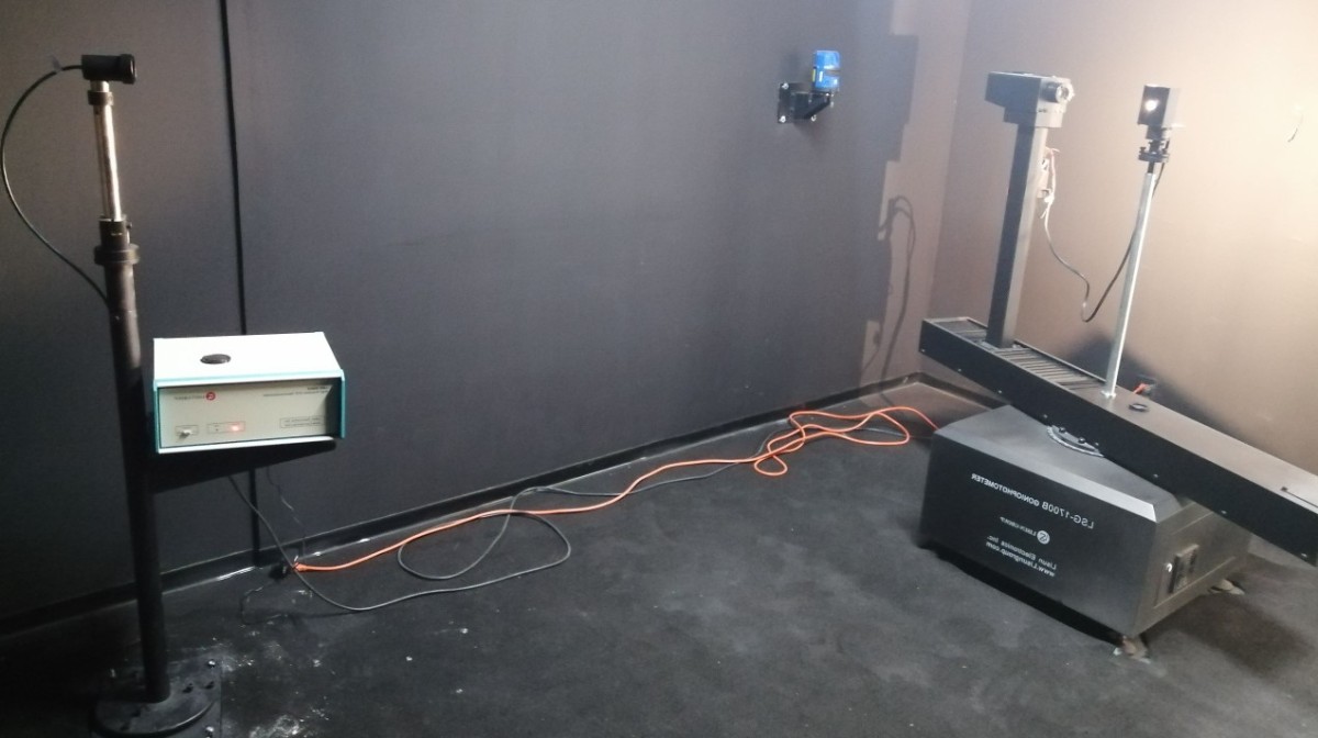
Figure 71
Close the darkroom door and ensure that all light sources in the darkroom are turned off except for the standard lamp. Click to enter the Spectroradiometer calibration interface.
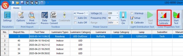
Figure 72
| Number | Note |
| ① | For the points accumulation time, be sure to always select “Automatic.” |
| ② | First, click “Sample.” Once sampling is complete, the corresponding curve will appear on the screen. After sampling is complete, the “Calibrate” button will become clickable. |
| ③ | Refer to the standard lamp calibration certificate and enter the specified color temperature value. |
| ④ | Click “Calibrate.” Once calibration is complete, the corresponding curve will appear on the screen. |
| ⑤ | Click OK to save and exit |
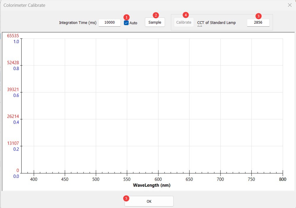
Figure 73
After calibration is complete, you can turn off the standard lamp using the software. Since the standard lamp becomes quite hot during use, wait for it to cool down before placing it back in its packaging for safe storage. Remove the calibration rod and store it safely.
6.4 Calibration and Maintenance
| No changes in the darkroom | If there have been no changes to the computer, recalibration is not necessary. |
| No changes have been made to the computer; simply unplug and replug the communication cable or reinstall the Goniophotomoeter software. No recalibration is necessary. | |
| If you replace your computer or reinstall the operating system, the photometric probe does not need to be recalibrated; simply enter the previous test distance and save it. However, the Spectroradiometer does need to be recalibrated (if you do not have the means to recalibrate it, please contact us to restore the calibration data). | |
| Changes in the Darkroom | The structure of the darkroom remains unchanged; however, after prolonged use, the interior paint may fade or peel. Depending on how well you maintain the darkroom and the level of accuracy you require for your test results, you may repaint the darkroom periodically. After repainting, the darkroom must be recalibrated. |
| There has been a change in the darkroom configuration, so recalibration is required. |
7. Preparations Before Testing
7.1 Lamp Selection and Aging
Select representative luminaires for testing that comply with national or corporate standards; new luminaires must undergo aging treatment (for LED luminaires, a 24-hour aging period is recommended);
Check that the light fixture has no visible damage, that the internal wiring is properly connected, and clean any stains from the surface of the fixture.
7.2 Introduction to Test Mode
C-Gamma Mode: Suitable for most lighting fixtures, including streetlights, downlights, panel lights, and plant grow lights.
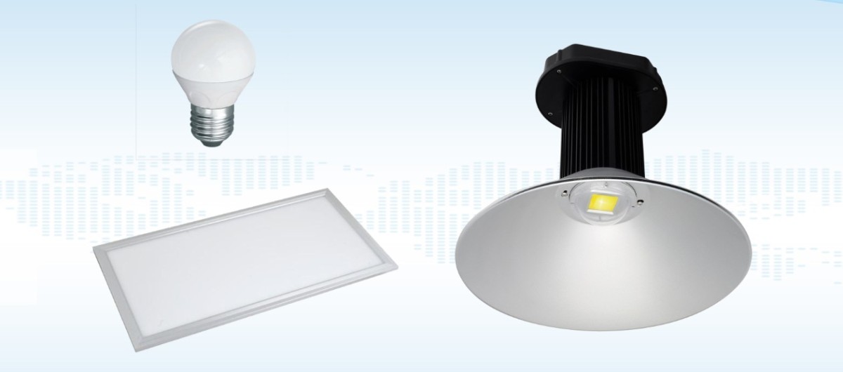
Figure 74
Beta Mode: Suitable for spotlights, floodlights, and similar fixtures; requires installation of an auxiliary arm.
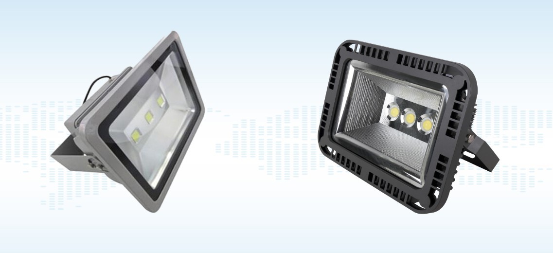
Figure 75
Alpha Mode: Suitable for automotive lights and signal lights.
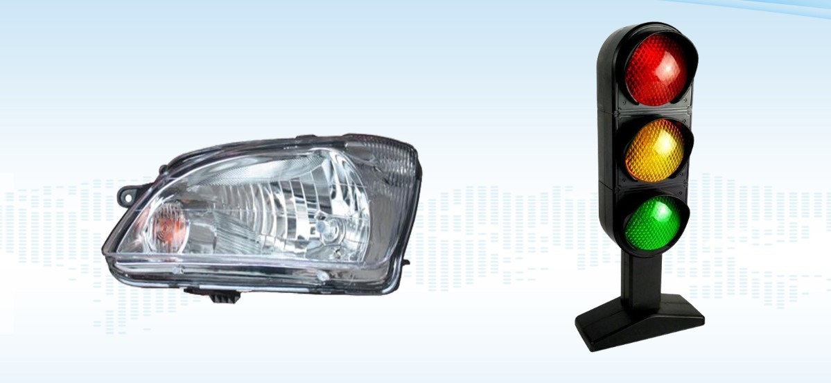
Figure 76
Note: The LSG-1890BCCD can be used for C-Gamma and B-Beta testing. For A-Alpha testing, a Type A goniophotomoeter is required; please contact us if needed.
8. C-Gamma Test
8.1 Luminous Intensity Distribution Test
8.1.1 Installing and Turning On the Light Fixture
8.1.1.1 Light Fixture Installation
We have two C-Gamma test fixtures; these operating instructions use the cross-shaped fixture as an example.
| Number | Note |
| ① | Large cross-shaped clamps are used for various types of lighting fixtures |
| ② | E27 Fixture for Testing Globe Bulbs |
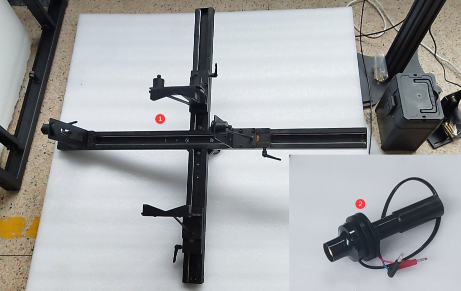
Figure 77
Attach the fixture to the Goniophotomoeter. Turn on the wall-mounted cross-line laser and verify that the crosshairs are projected accurately onto the markings on the opposite wall.
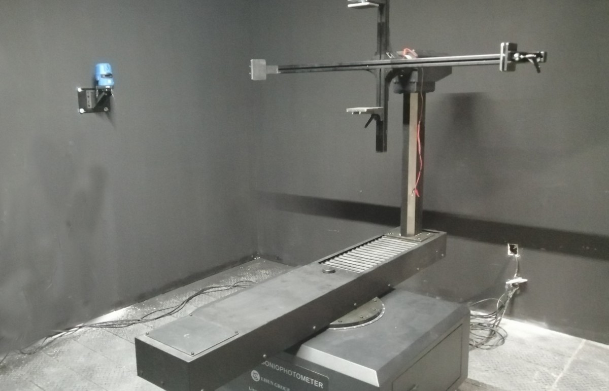
Figure 78
On the angle control interface, select the near-field photometric probe. Rotate the Gamma axis 90 degrees so that the crosshair laser points directly at the center of the crosshair fixture. Mount the luminaire under test onto the crosshair fixture. Adjust the position of the luminaire so that the crosshair laser is centered on the light-emitting surface of the luminaire under test, and the light-emitting surface is parallel to the crosshair fixture.
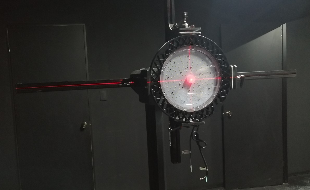
Figure 79
Then rotate the Gamma axis back to 0 degrees. Turn the dial here.
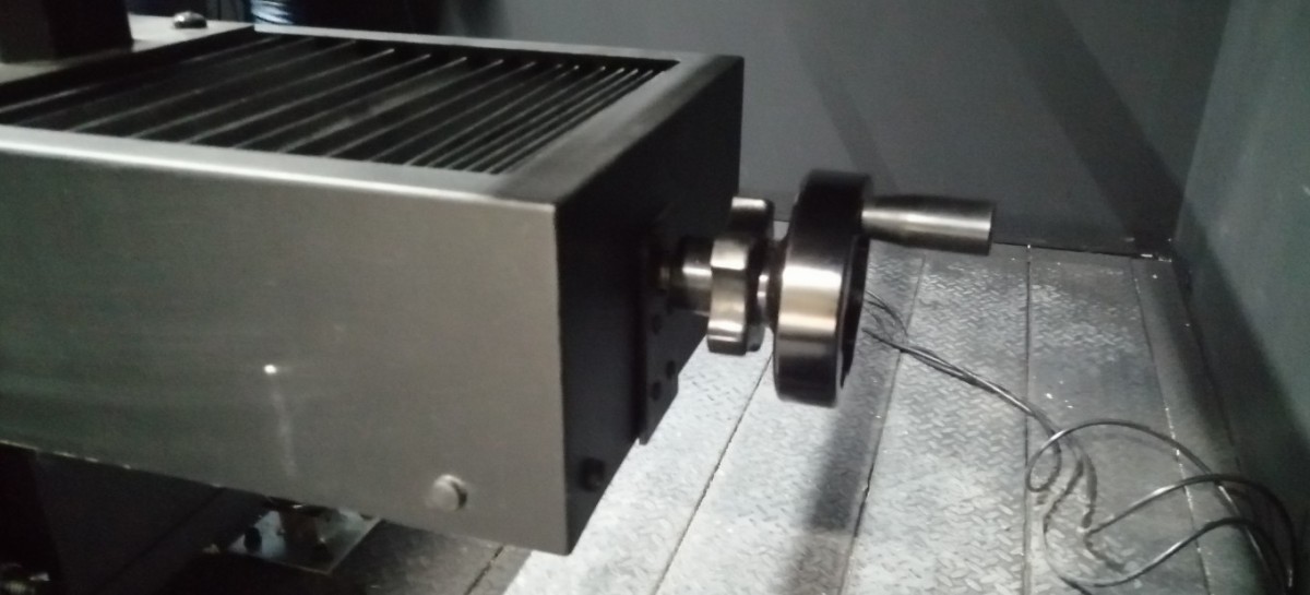
Figure 80
Align the light-emitting surface of the fixture with the vertical laser beam of the cross-hair laser.
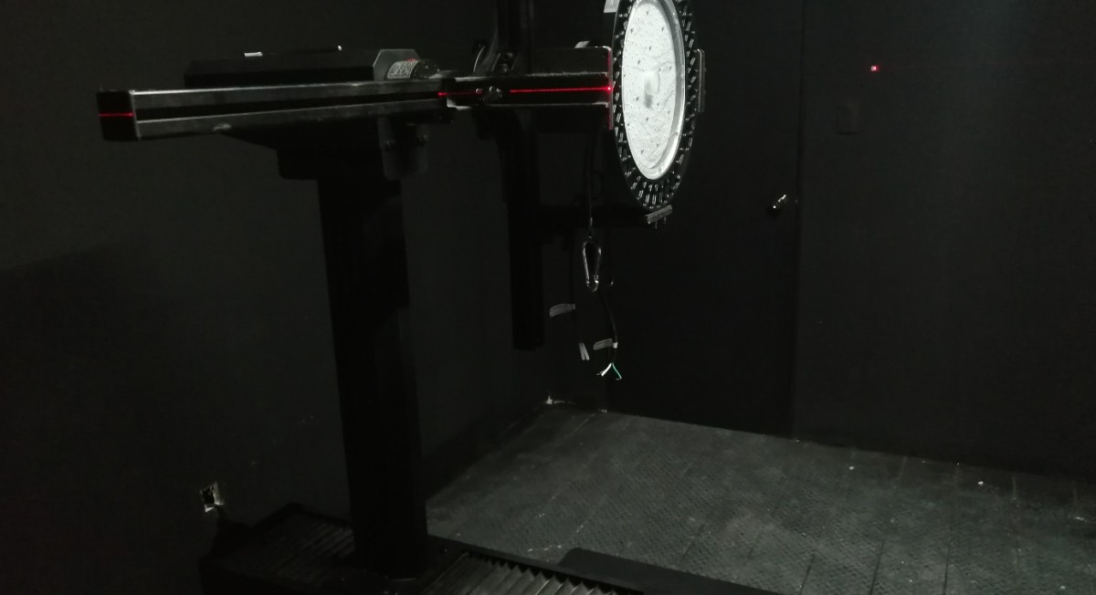
Figure 81
Caution is required when installing directional luminaires. When the angle of the C-plane on the Goniophotomoeter is 0 degrees, according to streetlight installation standards, the light pole should point straight upward, as shown in the figure below.
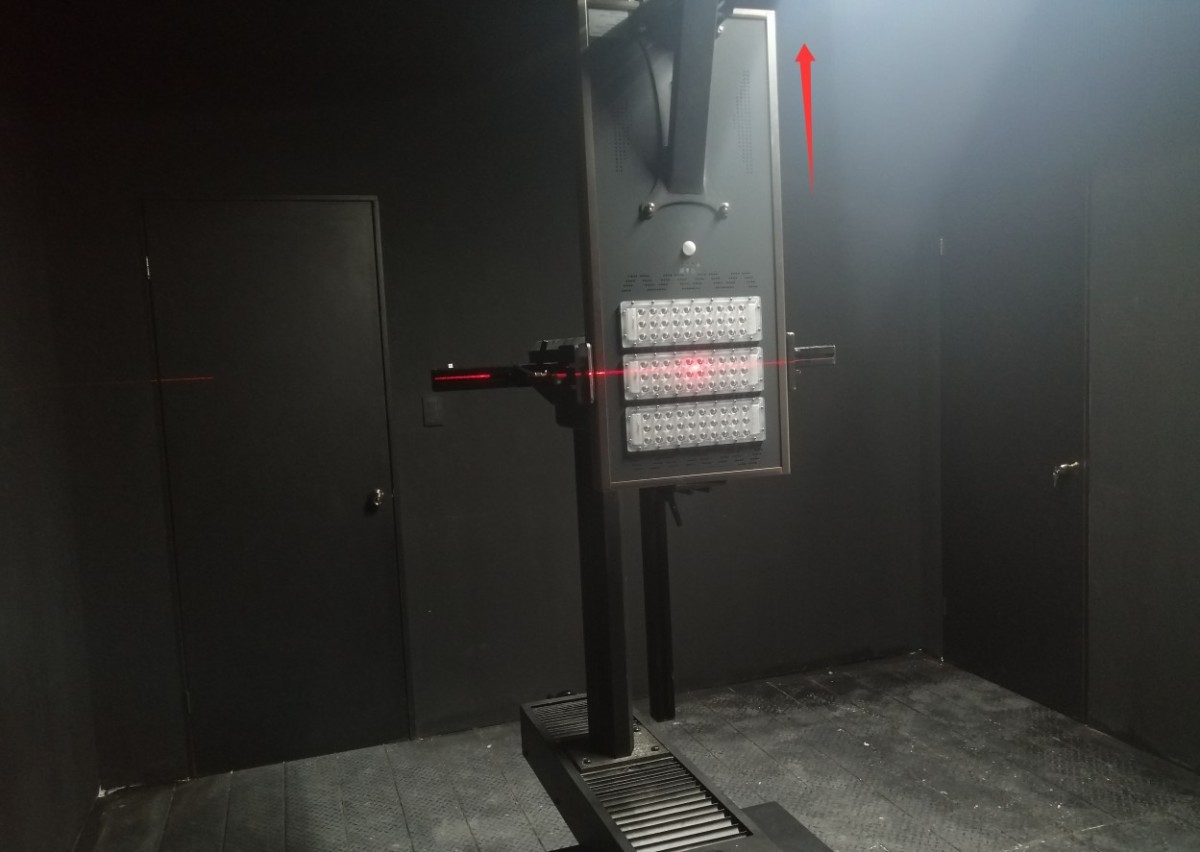
Figure 81.1
When the angle of the C-plane on the goniophotomoeter is 0 degrees, the bar light should be installed vertically in accordance with industry standards, as shown in the figure below.
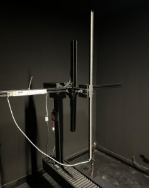
Figure 81.2
8.1.1.2 Lighting the Lamps
Connect the power cord to the luminaire under test. The connection method for the luminaire under test is the same as that for the standard luminaire; refer to Section 6.1.1.
Adjust the cabinet switch according to the parameters of the luminaire being tested.
| Number | Note |
| ① | If the sample luminaire is powered by AC, switch to the AC direction; if it is powered by DC, switch to the DC direction. |
| ② | Internal/External Sampling Switch for Electrical Parameters. External sampling uses a four-wire configuration and provides more accurate voltage readings. Unless otherwise specified, please set this switch to “External Sampling”; no further adjustments are necessary. |
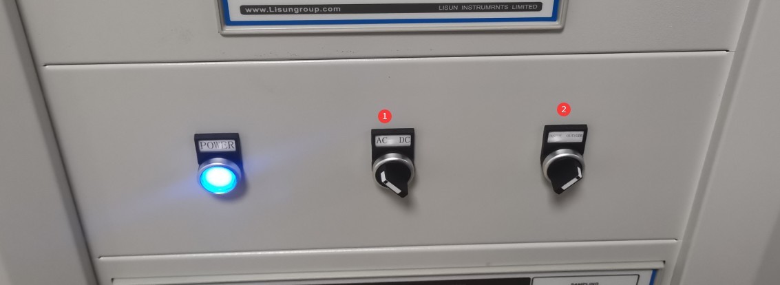
Figure 82
If the sample luminaire is AC-powered.
| Number | Note |
| ① | Select AC Power |
| ② | Based on the sample parameters, enter the correct voltage and frequency. |
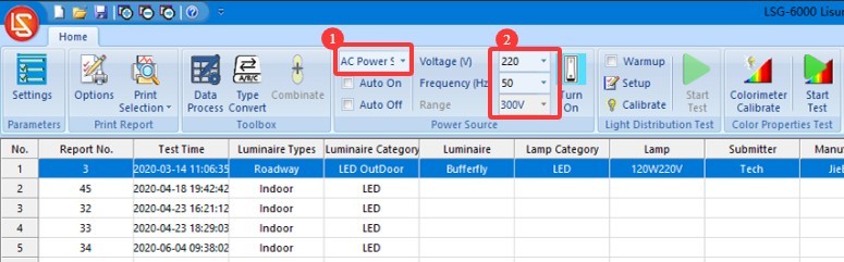
Figure 83
If the sample luminaire is DC-powered.
| Number | Note |
| ① | Select a DC Power Supply |
| ② | Based on the sample parameters, enter the correct voltage and current. |
| ③ | Select the output mode: CC stands for constant current, and CV stands for constant voltage. If you select constant current, you’ll need to enter the sample’s rated current value; for the voltage, simply enter the DC power supply’s maximum output voltage. If you select constant voltage, enter the sample’s rated voltage and the DC power supply’s maximum output current. Note: If your DC power supply model is DC3010, its maximum output voltage is 30 V and its maximum output current is 10 A. |
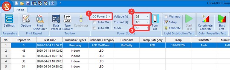
Figure 84
The software offers two methods for turning the sample lamp on and off, and users can choose freely between them.
| Number | Note |
| ① | If you check the “Auto Turn On” and “Auto Turn Off” options, the software will automatically turn on the sample at the start of the test using the selected power source and the entered electrical parameters, and will automatically cut off the sample’s power at the end of the test. |
| ② | If the “Auto On” and “Auto Off” options are not checked, you can still click this button. The software will turn on the sample based on the selected power source and the entered electrical parameters. Clicking this button again will turn off the sample’s power. |
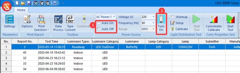
Figure 85
8.1.2 Preheating Parameter Settings
| Number | Note |
| ① | If you check the “Preheat” box, the software will preheat the luminaires according to the specified preheat parameters when the test begins, and the test will start automatically once preheating is complete. If you do not check the “Preheat” box, the software will begin the test immediately. |
| ② | Preheating Parameter Settings |
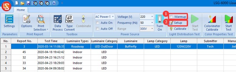
Figure 86
Click “Preheat Parameter Settings.”
| Number | Note |
| ① | Warm-up Duration Setting: The purpose of the warm-up is to allow the light fixture to remain on for a period of time until its luminous and color parameters stabilize, after which the test proceeds automatically. |
| ② | Sampling interval: The software will automatically take samples at the set interval throughout the entire warm-up period to obtain real-time data. We recommend setting this to 5 seconds or longer. |
| ③ | If checked, the test will automatically skip the remaining warm-up time and begin once the light fixture has reached a stable state; if unchecked, the test will begin only after the warm-up period has elapsed as set. |
| ④ | Definition of a luminaire’s steady state. If the values are set to 20 and 0.5%, the luminaire is considered to be in a steady state if the parameter has not varied by more than 0.5% over the past 20 minutes. |
| ⑤ | You can select which parameters the software should use to determine whether a light fixture is stable: optical parameters, electrical parameters |
| ⑥ | The software will save the change curves for the selected parameters during the warm-up period in the test report. |
| ⑦ | Once you’ve finished configuring the settings, click OK to save and exit. |
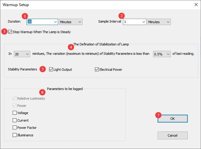
Figure 87
8.1.3 Configure Test Parameters and Start the Test
Click “Start Test.”
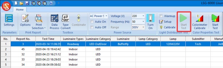
Figure 88
Go to the test parameter settings screen.
| Number | Note |
| ① | Lighting fixture types—indoor lights, outdoor lights, or plant grow lights—these three types of lighting fixtures are subject to C-Gamma testing. |
| ② | Select whether the luminaire is symmetrical. Unless there are specific requirements, select the first option, “Asymmetrical,” regardless of whether the luminaire being tested is symmetrical or not (to obtain the luminaire’s actual data). |
| ③ | C-plane angle range: Select 0 to 180 degrees; no modification is necessary. For data ranging from 180 to 360 degrees, the software will automatically convert the C-plane angle intervals. For symmetrical fixtures, such as indoor lights, you can select a larger interval, such as 30 degrees; for asymmetrical fixtures, such as streetlights, you can select a smaller interval, such as 10 degrees. The smaller the angle interval, the higher the test accuracy, but the longer the testing time. If time permits, it is recommended to select a smaller angle interval. |
| ④ | Gamma plane angle range: If the sample’s light irradiation angle exceeds 180 degrees (e.g., a globe lamp), select a range of -180 degrees to 180 degrees; if the sample’s light irradiation angle is less than 180 degrees (e.g., a panel light), you can select an angle interval for the Gamma plane ranging from -90 degrees to 90 degrees. Unless there are special requirements, selecting 1 degree is sufficient. The specific interval selected here has no effect on test speed. |
| ⑤ | If the system has multiple photometric probes, please select the one you want to use. |
| ⑥ | For standard luminaires undergoing routine testing, select “Normal Speed”; if the luminaire being tested has an extremely narrow beam angle, select “Slow Speed” to obtain more accurate test results; for expedited testing, select “Fast Speed.” |
| ⑦ | Fixed Range: If you are consistently measuring the same type of light fixture and the luminous intensity data does not vary significantly, you can check this box to save time. If you have ample time or frequently test lamps with different luminous intensities, it is recommended that you leave this box unchecked. In this case, the photometric probe will automatically select the appropriate range for each lamp. Continuous Scan Mode is suitable when the angle interval on the Gamma plane ranges from -180 degrees to 180 degrees. During the test, when the Gamma angle approaches ±180 degrees, while simultaneously rotating the C-axis to the next scan position—that is, the Gamma axis rotates continuously throughout the entire process to save time. If you have ample time, we recommend leaving this option unchecked. |
| ⑧ | To set the monitoring angle during the lamp warm-up phase, simply set it to (0, 0). |
| ⑨ | Normalization refers to the decision of whether to apply a uniform value to the first row of data in the light intensity table of a test report; certain standards, such as the U. S. streetlight standard, may require you to perform a similar adjustment. There are three options: no normalization, normalization to the maximum value (which will slightly increase the luminaire’s total luminous flux), and normalization to the average value (which leaves the luminous flux essentially unchanged). |
| ⑩ | If you need to remove all stray light outside a specific angle, check this option and enter the desired angle . For example, if you check this option and enter 60, data outside ±60 degrees of the luminaire’s gamma plane will automatically be set to 0. |
| ⑪ | Enter the number of light sources in the luminaire and the rated luminous flux of each light source. If you do not know this information, you may leave it blank; it will not affect the test results. |
| ⑫ | Enter the dimensions of the sample’s light-emitting surface. For indoor lighting fixtures, the software requires this data to calculate the luminance limit curve, UGR, and other parameters. |
| ⑬ | Enter information about the sample light fixture |
| ⑭ | Enter the temperature and humidity of the test environment (i.e., the darkroom) |
| ⑮ | Click OK to proceed to the warm-up screen, or to the test screen. |
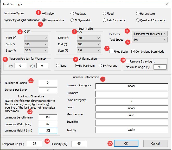
Figure 89
Then wait for the software testing to complete. Once testing is complete, refer to Section 8.2 to perform the chromaticity distribution test.
8.2 Chromaticity Distribution Test
After completing the C-Gamma luminous intensity distribution test, a chromaticity distribution test can be conducted based on the test report.
Note: The software automatically calculates the spatial angle range required for the chromaticity distribution test based on the photometric distribution test report. Therefore, if a photometric distribution test is not performed, a chromaticity distribution test cannot be conducted directly.
Select the photometric distribution test report for this luminaire, then click to open the chromaticity distribution test parameter settings interface.
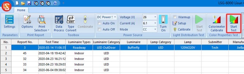
Figure 90
| Number | Note |
| ① | If checked, only the chromaticity characteristics test will be performed; the chromaticity distribution test will not be performed. If unchecked, both the chromaticity characteristics test and the chromaticity distribution test will be performed. |
| ② | Selection of test positions for colorimetric characteristics. The “optical axis” refers to the position directly in front of the light-emitting surface of the sample luminaire; the “point of maximum luminous intensity” refers to the position where the luminous intensity of the sample luminaire is greatest. |
| ③ | The angle range for the C-plane is 0 to 360 degrees. There is no need to adjust the angle increment for the C-plane. For symmetrical fixtures, such as indoor lights, a larger increment—for example, 30 degrees—can be selected, while for asymmetrical fixtures, such as streetlights, a smaller increment—for example, 10 degrees—can be selected. The smaller the increment, the higher the testing accuracy, but the longer the testing time. |
| ④ | The gamma plane angle range is automatically calculated by the software based on the results of the photometric distribution test. There is no need to adjust the angle intervals of the gamma plane. You may also select a larger angle interval; symmetrical luminaires, such as indoor lights, can use a larger interval—for example, 10 degrees—while asymmetrical luminaires, such as streetlights, can use a smaller interval—for example, 5 degrees. The smaller the interval, the higher the test accuracy; however, the test will take longer. |
| ⑤ | Once you’ve finished configuring the settings, click “Start” to begin the test, and wait for the software to automatically complete the self-test. |
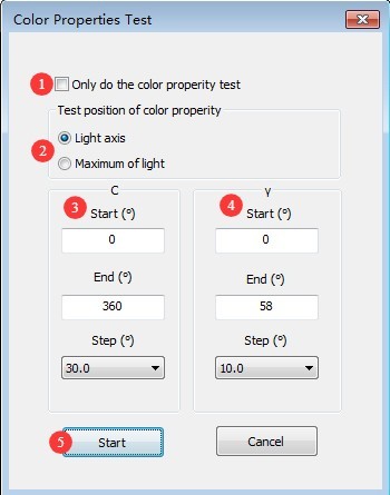
Figure 91
9. B-Beta Testing
9.1 Luminous Intensity Distribution Test
9.1.1 Installing and Turning On the Lights
9.1.1.1 Light Fixture Installation
Turn on the crosshair laser and make sure it is still projected onto the mark you made on the opposite wall.
Find the square B-Beta test fixture.
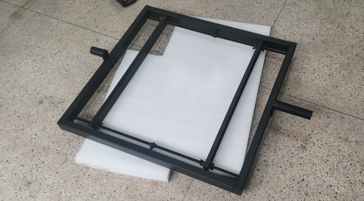
Figure 92
When performing the B-Beta test, reattach the Goniophotomoeter’s auxiliary arm. Then, install the B-Beta fixture vertically as shown in the figure.
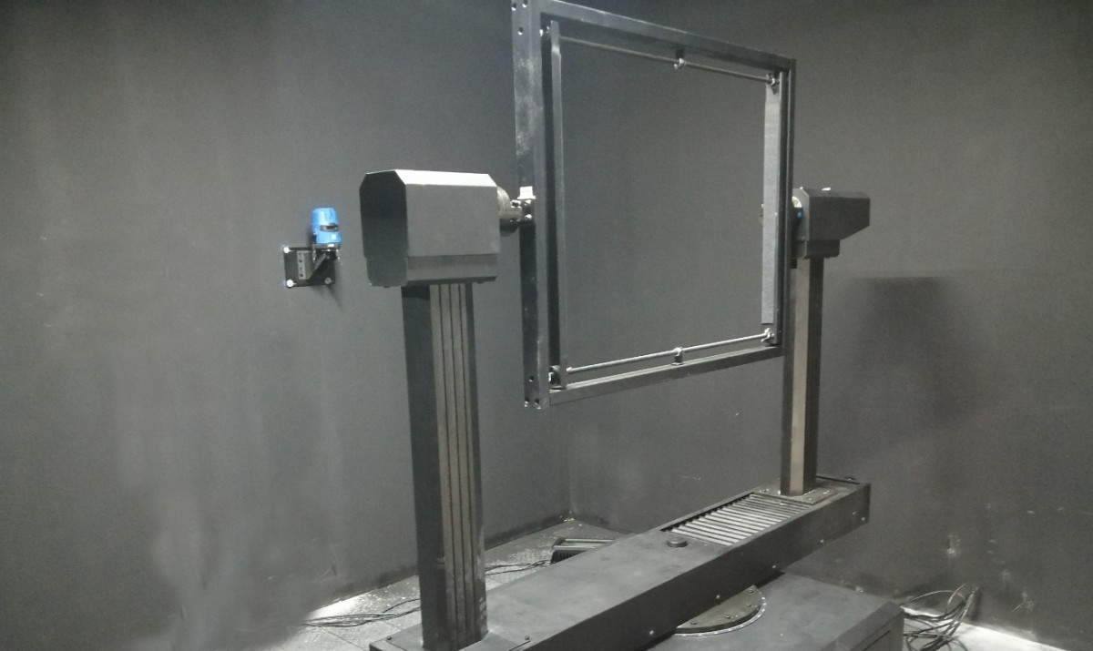
Figure 93
| Number | Note |
| ① | Click to switch the viewing angle |
| ② | Click ① to display the B-Beta angle here instead of the C-Gamma angle. |
| ③ | Click to open the angle control interface |
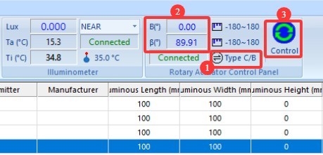
Figure 94
| Number | Note |
| ① | When angle B is 0 degrees, the fixture should be in a vertical position; this can be verified using a level. |
| ② | Enter 0 |
| ③ | Click to set the Beta angle to 0 degrees. Note: The 0-degree position for the Gamma angle is not the same as the 0-degree position for the Beta angle. |
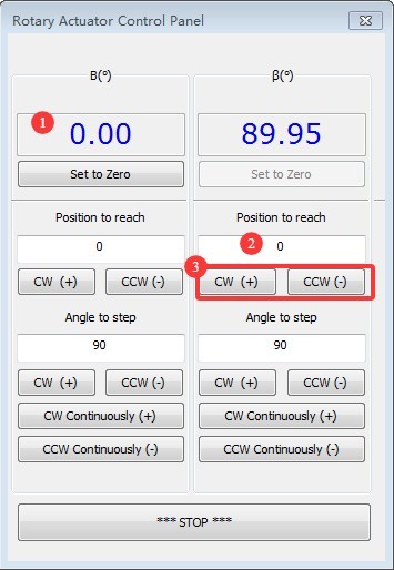
Figure 95
After rotating Beta to the 0-degree position, mount the floodlight onto the fixture, ensuring that the light-emitting surface faces the photometric probe. Adjust the position of the fixture so that the cross-shaped vertical laser beam aligns with the light-emitting surface of the fixture.
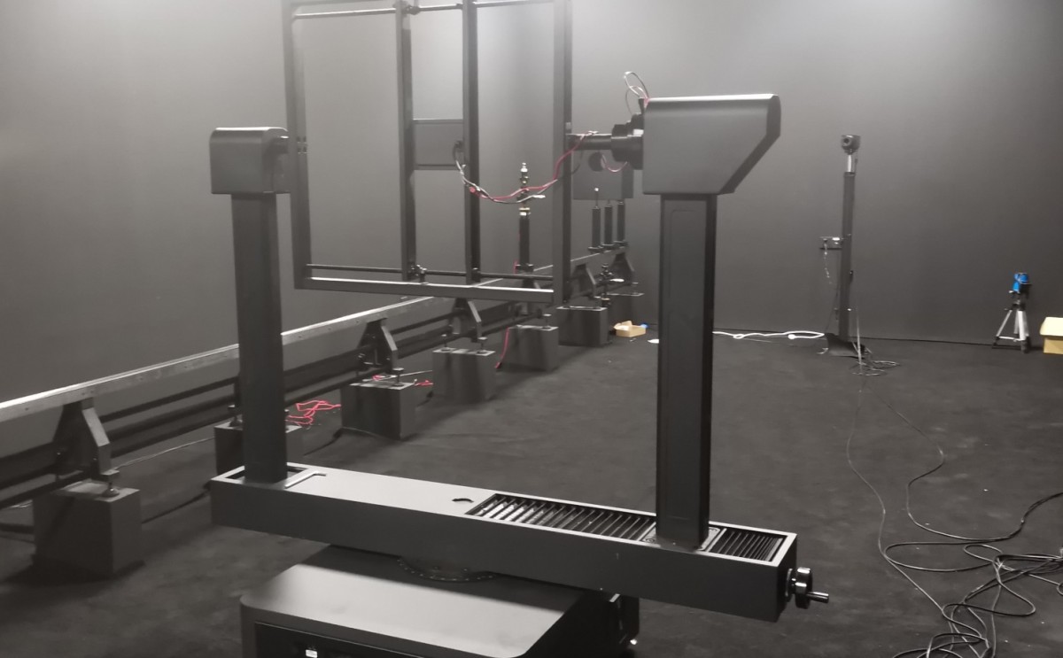
Figure 96
To ensure the sample is positioned exactly in the center of the Goniophotomoeter, rotate the Beta fixture to the position shown in the figure below so that the sample’s light-emitting surface faces the crosshairs. Use the crosshairs to fine-tune the position of the sample holder.
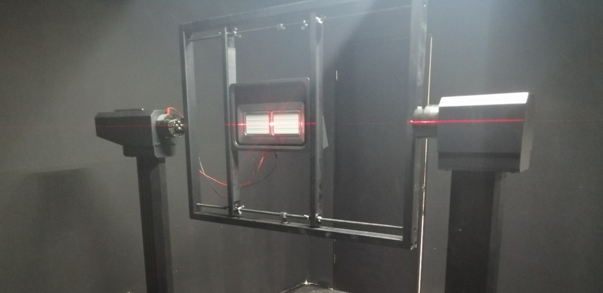
Figure 97
Once the light fixture is installed, you can turn off the cross-line laser.
9.1.1.2 Turning on the Lights
Please refer to 8.1.1.2.
9.1.2 Preheating Parameter Settings
Please refer to 8.1.2.
9.1.3 Configure Test Parameters and Start the Test
Click “Start Test” to open the test parameter settings screen.
| Number | Note |
| ① | Please select “Floodlight,” and the test mode will automatically switch to B-Beta. |
| ② | The angle range for Plane B is -90 degrees to 90 degrees. There is no need to adjust the angle increments for Plane B; you can select smaller increments, such as 5 degrees or 10 degrees. The smaller the increment, the higher the test accuracy, but the longer it takes. |
| ③ | The Beta plane angle range is -90 degrees to 90 degrees. There is no need to adjust the angle interval for the Beta plane; unless there are special requirements, select 1 degree. Different angle intervals here have no effect on test speed. |
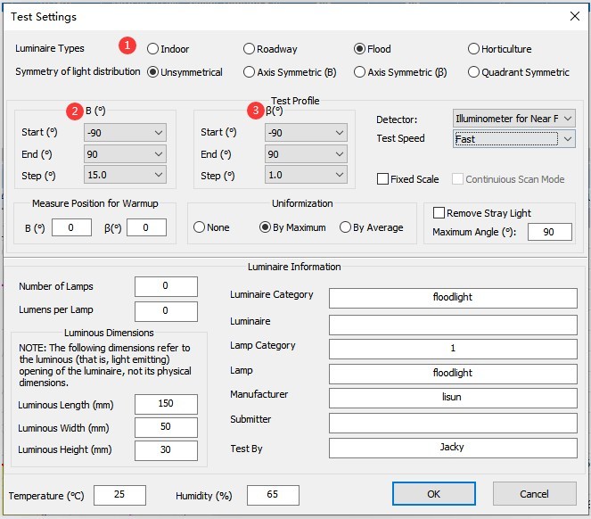
Figure 98
For other parameter settings, refer to Section 8.1.3. Once the settings are configured, click “Start” and wait for the software to complete the test. After the test is complete, refer to Section 9.2 to perform a chromaticity distribution test.
9.2 Chromaticity Distribution Test
After completing the B-Beta photometric distribution test, a chromaticity distribution test can be conducted based on the test report.
Select the photometric distribution test report for this luminaire, then click to open the chromaticity distribution test parameter settings interface.
| Number | Note |
| ① | The angle range for Plane B is automatically calculated by the software based on the results of the photometric distribution test; there is no need to adjust the angle intervals for Plane B. Options include 5 degrees and 10 degrees. The smaller the interval, the higher the test accuracy, but the longer it takes. |
| ② | The beta-plane angle range is automatically calculated by the software based on the results of the photometric distribution test; there is no need to adjust the beta-plane angle intervals, which can be set to, for example, 5 degrees or 10 degrees. The smaller the interval, the higher the test accuracy, but the longer it takes. |
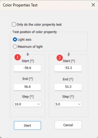
Figure 99
For other parameter settings, please refer to Section 8.2. Once the settings are configured, click “Start” and wait for the software to automatically complete the test.
10. Processing of Test Reports
10.1 Organizing Database Files
| Number | Note |
| ① | By default, all test reports are automatically stored in the currently open database file in the order in which the tests were run. |
| ② | To delete a report, select it and then click “Delete.” |
| ③ | To make it easier to find test reports, click the blank button shown in the image below to create a new database file, and store the reports for different luminaires in separate database files. After creating a new database file, you can proceed directly with testing without needing to recalibrate or reconfigure the system. |
| ④ | Click “Open” to view test reports from other database files. |
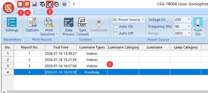
Figure 100
Note 1: The next time the software is opened, it will automatically load the database file used last time. If the path to that database file has changed or its name has been modified, the software will prompt you to create a new database file.
Note 2: Avoid placing database files on your computer’s desktop whenever possible.
10.2 Test Report Display Settings
| Number | Note |
| ① | You can double-click to upload a picture of the light fixture. |
| ② | You can double-click to edit the content displayed in this area. |
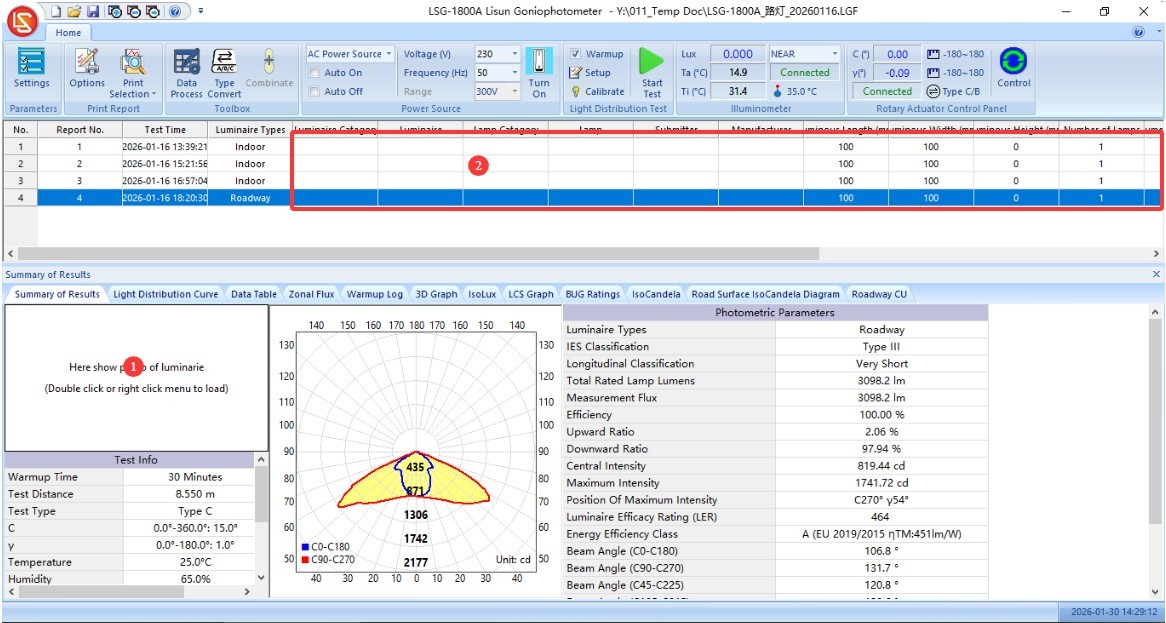
Figure 101
| Number | Note |
| ① | Click “Settings” |
| ② | For unit selection, “cd” is generally used; however, some older standards—such as those regarding energy-saving lamps—may require the use of “cd/klm.” |
| ③ | Streetlight C0 angle setting. The CIE/GB and IESNA standards have inconsistent requirements; please select the standard you are following. |
| ④ | Customize the divergence angle. The software automatically displays the half-peak angle (commonly referred to as the beam angle, calculated as 50% of the maximum luminous intensity) and the effective beam angle (calculated as 10% of the maximum luminous intensity). If you wish to customize the divergence angle, enter the percentage of the maximum light intensity and check the box (e.g., 0.25 for 25%). In this case, the test report will display your custom divergence angle in addition to the half-peak angle and effective beam angle. |
| ⑤ | Check this box to display the maximum luminous intensity cone angle in the report. |
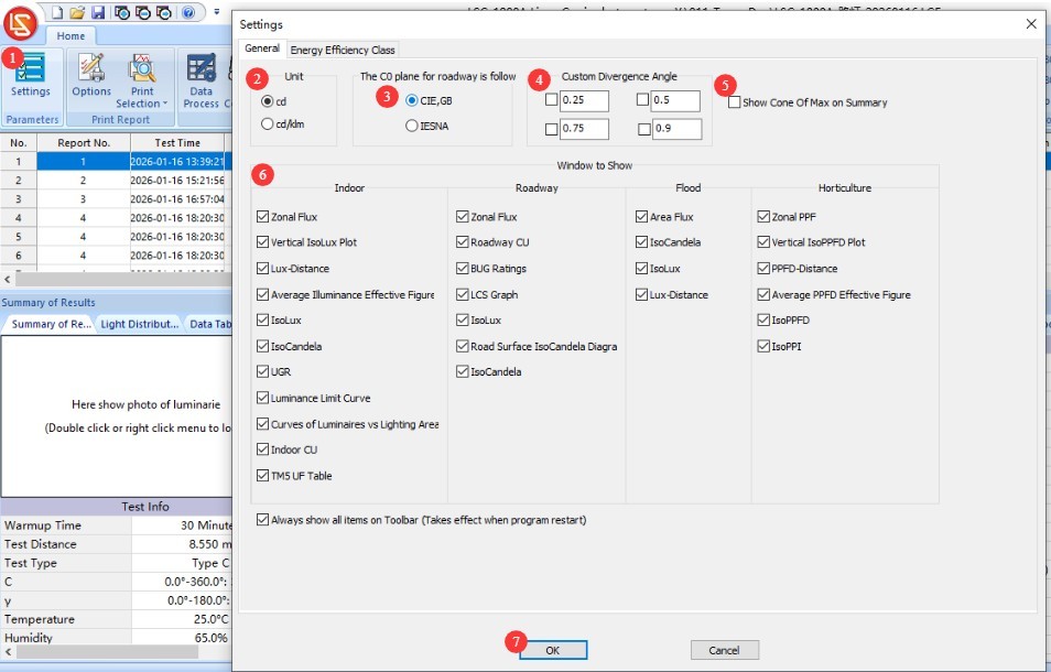
Figure 102
| Number | Note |
| ① | Switch to the “Energy Efficiency Rating” settings screen, then select the applicable standard and luminaire type. |
| ② | Click to apply to the current test report |
| ③ | Click OK to save and exit |
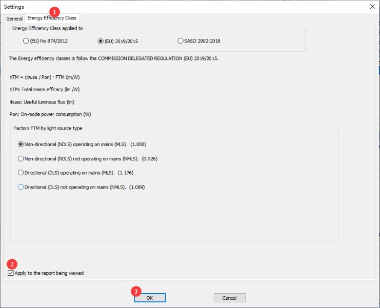
Figure 103
Each display window has several options for customizing the display settings. Users are encouraged to experiment with adjusting these settings.
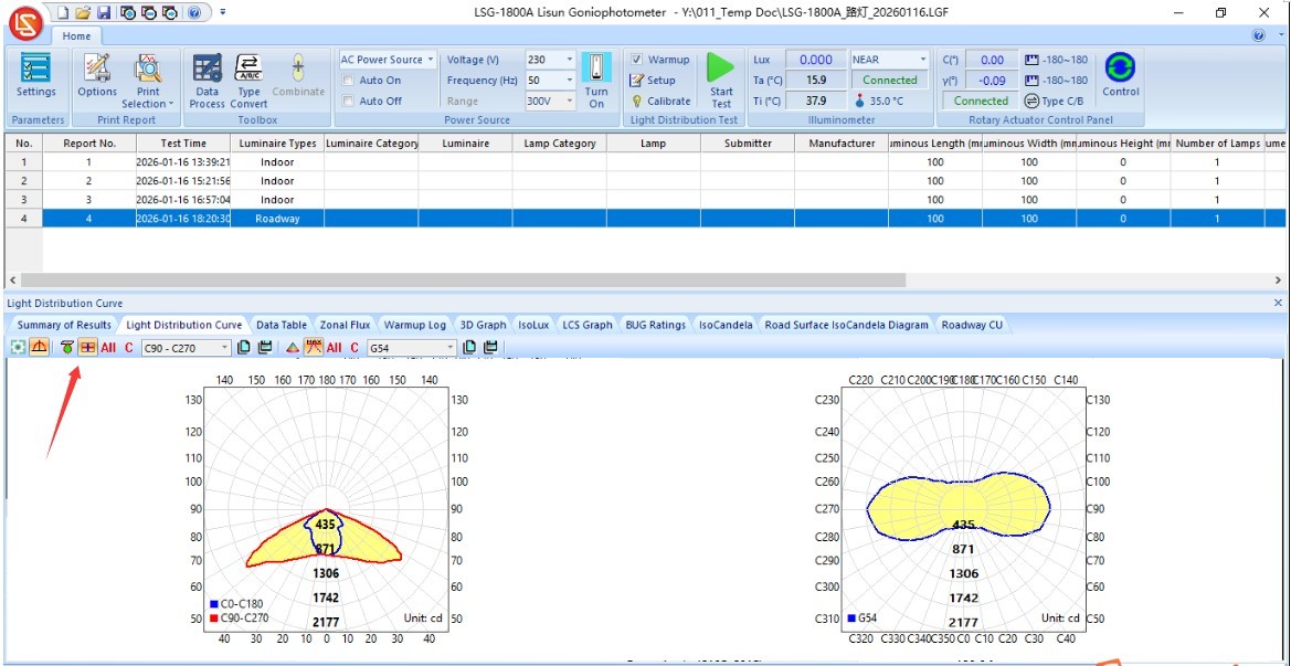
Figure 103.1
10.3 Processing of Test Data
10.3.1 Double-Sided Light Fixtures
For lamps that emit light from both sides, use the indoor lighting test mode to test each side individually—that is, set the gamma plane angle range to -90 degrees to 90 degrees during testing—and then generate two test reports.
| Number | Note |
| ① | Hold down the “Ctrl” key on your keyboard, then click to select the two test reports you just received. |
| ② | Click “Data Synthesis” in the software navigation bar |
| ③ | In the pop-up window, you can click to switch between the upward and downward light beams. |
| ④ | Select “Composite” |
| ⑤ | Click OK to save and exit |
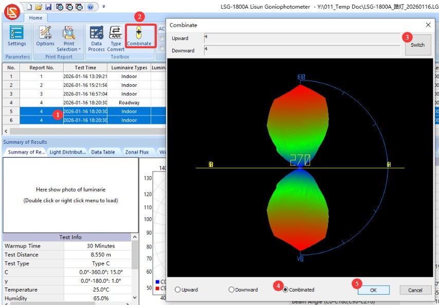
Figure 104
This will generate a new synthetic test report, as shown in the figure below.

Figure 105
10.3.2 Conversion of Test Report Types
| Number | Note |
| ① | Click “Type Conversion” |
| ② | Test reports can be converted among four types. |
| ③ | When converting to a C-Gamma test report, you can use the “termination angle” of the C-plane to generate a symmetric test report. If the termination angle is set to 360 degrees, there will be no symmetry; if the termination angle is set to 180 degrees, the report can be converted into an axis-symmetric test report; if the termination angle is set to 90 degrees, it can be converted into a quadrant-symmetric test report; if the termination angle is set to 0 degrees, it can be converted into a fully symmetric test report. This feature is primarily intended for symmetric indoor lighting fixtures; certain lighting design software programs, such as DIALUX, may require you to use it when importing fully symmetric IES files. |
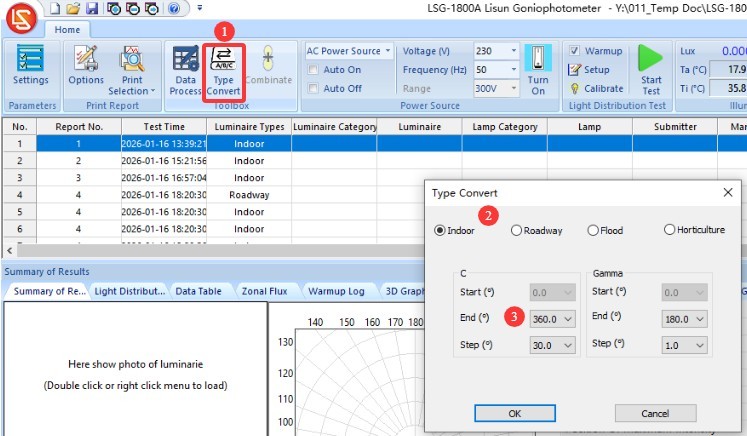
Figure 106
10.4 Exporting Test Data and Printing Test Reports
10.4.1 Exporting Test Data
| Number | Note |
| ① | Click the red logo in the upper-left corner of the software |
| ② | Click “Export Data” in the drop-down menu |
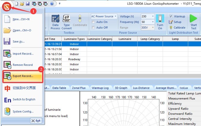
Figure 107
Files can be exported in a variety of standard formats.
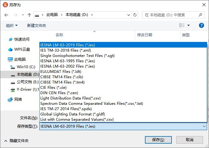
Figure 108
10.4.2 Printing Test Reports
Print settings.
| Number | Note |
| ① | Click to open the “Print Settings” screen |
| ② | The report displays language options; you can choose between Chinese and English. |
| ③ | Page Number Format |
| ④ | Report Header Information |
| ⑤ | Report Titles in Chinese and English |
| ⑥ | General Report Content, Applicable to Reports on All Types of Lighting Fixtures |
| ⑦ | Since indoor lights, streetlights, floodlights, and plant grow lights have different key parameters, the report content will vary accordingly. You can select the specific items you want to include in the report. |
| ⑧ | TM-30 Options |
| ⑨ | CIE color space diagram or SDCM color tolerance diagram—only one of the two may be selected |
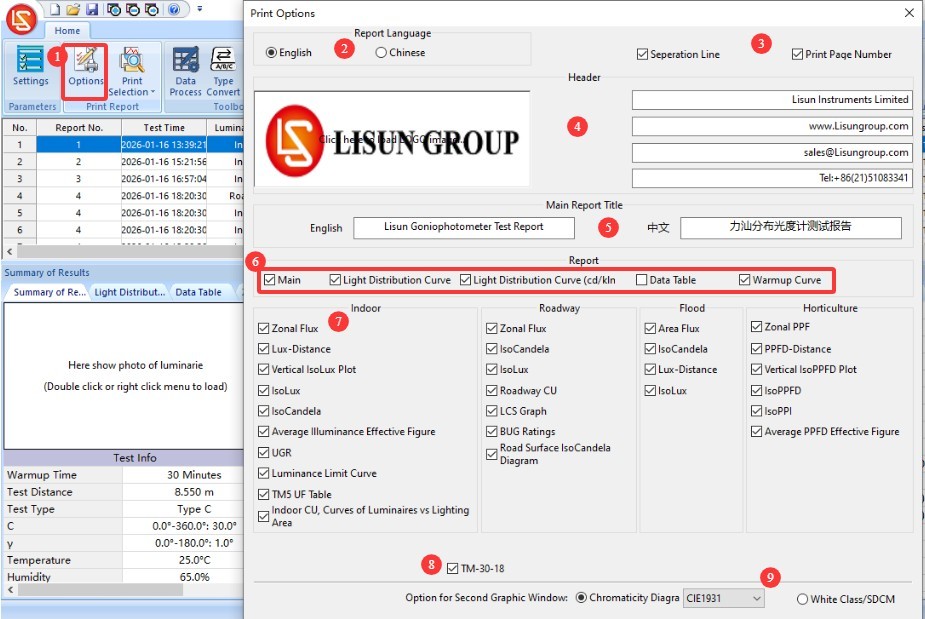
Figure 109
| Number | Note |
| ① | Click to print the currently selected test report |
| ② | Click to print all test reports in the current database file |
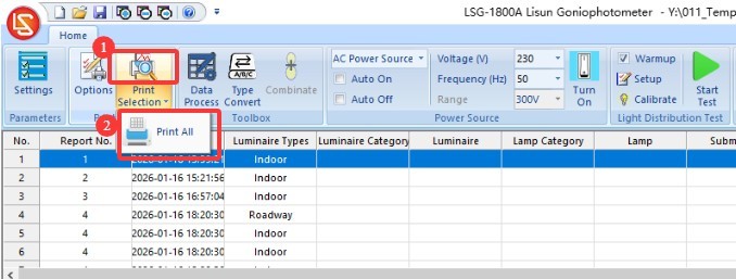
Figure 110
11. Daily Maintenance and Care of Equipment
11.1 Routine Maintenance
Start-up procedure: First, turn on the cabinet’s main power switch; then, turn on the power switches for the equipment inside the cabinet and in the darkroom one by one; finally, launch the software. Shutdown procedure: First, close the software; then, turn off the power switches for the equipment inside the cabinet and in the darkroom one by one; finally, turn off the cabinet’s main power switch.
Keep the darkroom control room clean and dust-free to prevent dust from entering the equipment. If there is dust on the surface of the equipment, wipe it off with a dry, soft cloth.
Avoid exposing the darkroom to high humidity for extended periods; keep a dehumidifier on hand if necessary.
11.2 Routine Maintenance
11.2.1 Cleaning The Optical Fiber Of the Photometric Probe
If the darkroom cannot be kept dust-free, the photometric probe and the light-sensitive surface of the Optical Fiber should be cleaned regularly (for example, once a month) based on actual conditions to prevent dust buildup, which could affect test accuracy.
When cleaning, please use a professional lint-free cloth to remove dust and prevent scratches on the device.
11.2.2 Standard Lamp
The standard lamp is valid for one year. If you still need to calibrate the darkroom after one year, we recommend purchasing a new standard lamp.
11.2.3 Software
We update the software from time to time to add features and fix bugs. If you encounter any issues while using the software, please feel free to contact us at any time to obtain the latest version.
11.3 Long-Term Decommissioning and Maintenance
11.3.1 Equipment Cleaning and Protection
Thoroughly clean all equipment surfaces, and cover the main unit, probe, spectrometer, and cabinet with dust-proof cloths; disconnect all power sources.
11.3.2 Environmental Protection
Ensure that the darkroom is dry and well-ventilated to prevent equipment from becoming damp. If the ambient humidity is high, keep a dehumidifier on hand.
11.3.3 Monthly Power-On
Conduct a power-on test once a month to ensure that all system hardware is functioning properly.
12. Troubleshooting and Resolving Common Problems
12.1 Communication Errors
Cause of the problem: Check that the communication cable is securely connected and that it is not plugged into the wrong port; verify that the drivers are installed correctly; try a different USB port or communication cable to rule out hardware issues.
Solution: Reinstall the driver, connect the communication cable according to the device identifier, restart the software, and try again.
12.2 Test Errors
12.2.1 Luminous Flux Anomalies
Cause of the malfunction: Check whether the light source is stable and whether the warm-up time is sufficient; verify that the device is properly calibrated, that the test distance is correct, and that the standard light is functioning properly; check whether there is any external light interference in the darkroom and whether the light path is obstructed.
Solution: Extend the warm-up time, recalibrate the instrument, turn off other light sources in the darkroom, and remove any obstructions from the optical path.
12.2.2 UGR Anomalies
Cause of error: Dimensions of the luminaire’s light-emitting surface were not entered; the luminaire’s beam angle is <45°; incorrect calculation standard was selected
Solution: Enter the dimensions of the luminaire’s light-emitting surface (length/width/height) correctly; verify that the luminaire is an indoor luminaire (the beam angle must be sufficient); select the CIE 190:2010 standard and recalculate.
12.2.3 Abnormal Chromaticity Distribution Test Results
Cause of the malfunction: The test was not conducted based on the current luminaire’s photometric distribution test report; the light intensity was too low, preventing the Spectroradiometer from properly acquiring the colorimetric parameters.
Procedure: Please first conduct a luminous intensity distribution test, and then perform a color distribution test based on that report; if the luminaire’s luminous intensity is too low, please contact us for the best solution.
12.3 The Goniophotomoeter does not rotate
Cause of the malfunction: Check whether the host power is on and whether the wiring is correct; check whether the angle controller inside the cabinet is operating normally; confirm whether any foreign objects are jammed in the rotary shaft.
Solution: Check the power supply and wiring, and remove any foreign objects; restart the device and software, then try again.
12.4 Software Failures
12.4.1 Software Crashes
Cause of the problem: Check whether you are logged in to the computer’s operating system with an administrator account; verify that the software is fully installed; check whether the database files are corrupted.
Solution: Log in to the computer using an administrator account; reinstall the software and drivers; create a new database file.
12.4.2 The software displays the message “File is not a database”
Cause of the problem: The database file was deleted or moved; the default program used to open LGF files was changed.
Solution: Create a new database file and save it; restore the default program for opening LGF files.
12.5 Power Failure
12.5.1 DC Power Output Abnormalities
Causes of the malfunction: The AC/DC switch on the cabinet was not set to DC; the sample voltage or current exceeded the DC power supply limits; a short circuit in the sample;
Troubleshooting: Please verify that the sample’s voltage and current are within the DC power supply’s output range. For example, the DC3005 model has a maximum output voltage of 30 V and a maximum output current of 5 A. Check whether the sample is short-circuited; if so, repair the sample before retesting.
12.5.2 No AC Output
Cause of the fault: The AC/DC switch in the cabinet was not set to the AC side; the overload protection was triggered;
Troubleshooting Steps: Check the AC power output wiring and sample connections to ensure there are no loose connections or short circuits; if the overload protection is triggered, turn off the power, allow the unit to cool for 5 minutes, and then restart it. Ensure that the sample power remains within the AC power output range—for example, the LSP-500VARC has a maximum output power of 500 W.