
 English
 中文简体
中文简体 English
 Русский
 Español
 Português
 Türkçe
 العربية
 Deutsch
 Polski
 Italiano
 Français
 한국어
한국어 ไทย
ไทย Tiếng Việt
 日本語
日本語





























Dustproof Testing Machine
User's Manual
Applicable LISUN models: SC-010、SC-015、SC-020、SC-500
1. Unboxing and Basic Familiarization with the Device
1.1 Key Technical Specifications
| Model | Working Dimensions (mm) | Notes | Door Opening Methods |
| SC-500 | 800×800×800 | Fully complies with GB/T 4208-2017 Clauses 13.4–13.6 and Figure 2 (IEC 60529:2013 Clauses 13.4–13.6, Figure 2) regarding IP5X and IP6X testing | Single Door |
| SC-010 | 1000 × 1000 × 1000 | ||
| SC-015 | 1000 × 1500 × 1000 | Double Doors | |
| SC-020 | 1000 × 2000 × 1000 | ||
| SC-010-56K | 1000 × 1000 × 1000 | Fully complies with GB/T 4208-2017 Clauses 13.4–13.6 and Figure 2 (IEC 60529:2013 Clauses 13.4–13.6, Figure 2) regarding IP5X and IP6X testing, GB/T 30038 Figure 1 (ISO 20653 Figure 1) regarding IP5KX and IP6KX testing | Single Door |
| SC-015-56K | 1000 × 1500 × 1000 | Double Doors | |
| SC-020-56K | 1000 × 2000 × 1000 |
1.2 Unboxing and Checking the Accessories
1.2.1 Unpacking and Visual Inspection
When unpacking the device, handle it gently to avoid scratching the casing with sharp objects. After unpacking, first inspect the exterior of the device to ensure there is no visible deformation or dents, and that the buttons are not damaged or loose. If you notice any abnormalities with the device or its accessories, do not turn it on. Please contact us immediately.
1.2.2 Main Unit and Accessories
SC Series Dustproof Testing Machine: 1 unit.
The main components are as follows:
| No. | Note |
| ① Medical talcum powder | Used for testing in simulated sandstorm conditions. This is a consumable item; please purchase a replacement when it runs out. |
| ② Screen | Metal square-mesh screen, with a wire diameter of 50 μm and a mesh size of 75 μm, used for filtering talc powder |
| ③ Cleaning Tools | For use when removing talcum powder from the test chamber |
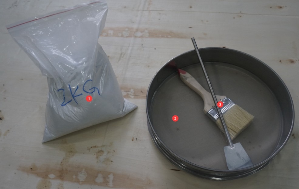
Figure 1
Download links for the digital user manual, software, warranty card, and other materials have been sent via email. Please download them as soon as possible. If you missed the email, you may also contact us to request the download links again.
1.3 Description of the Test Chamber Structure
1.3.1 Front of the Test Chamber
| No. | Note |
| ① | Power Switch |
| ② | Emergency Stop |
| ③ | Touchscreen |
| ④ | Pressure control knob: used to adjust the pressure differential inside the sample when using a vacuum pump; Pressure gauge: displays the real-time pressure inside the sample in kPa, with an adjustment range of -10 to 10 kPa. |
| ⑤ | Air flow meter, displays the vacuum pump’s pumping speed, 0–4800 L/h |
| ⑥ | Test chamber doors come in two types: single-door and double-door. |
| ⑦ | Viewing window, with dust scraper |
| ⑧ | The bottom panel of the test chamber can be opened to clean talcum powder from the interior of the test chamber. Note: The bottom panel of the test chamber may be located on the front or on the side of the test chamber. |
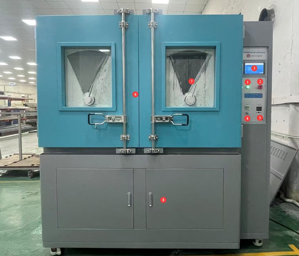
Figure 2
1.3.2 Rear of the Test Chamber
| No. | Note |
| ① | Circuit Breaker |
| ② | A talc powder filtration device that prevents talc powder from entering the vacuum pump when the vacuum pump is in use |
| ③ | Power terminals for the sample: Please connect the sample to an appropriate power source. Note: Abnormal conditions, such as short circuits, may occur during testing; an external ground-fault circuit interrupter may be connected here. |
| ④ | Test Chamber Power Cord |
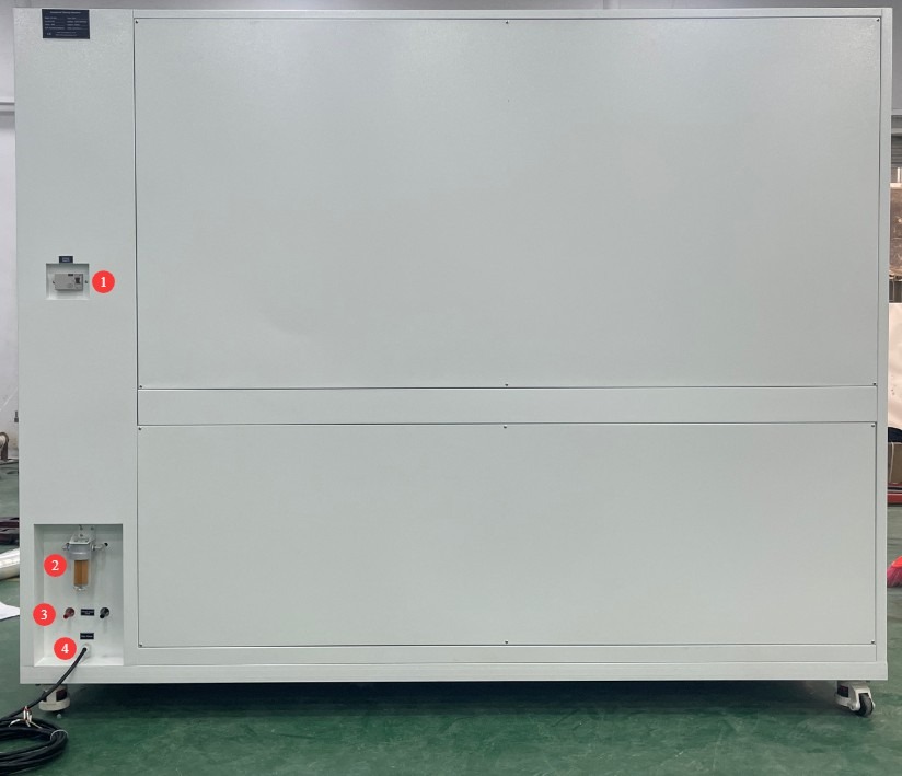
Figure 3
1.3.3 Inside the Test Chamber
| No. | Note |
| ① | Exhaust port—talc powder is blown out through this opening during testing |
| ② | Lighting: Can be turned on to facilitate observation of the interior of the test chamber during testing. |
| ③ | Dust-proof outlet and plug, used to connect the sample’s power cord |
| ④ | Sample Connection and Placement |
| ⑤ | Vacuum pump hose, used during negative pressure dustproof testing of Type I enclosures. When not in use, please seal it to prevent talcum powder from entering. |
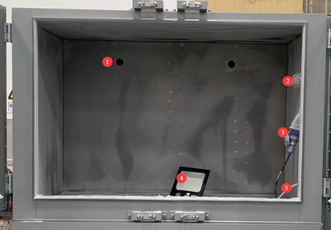
Figure 4
2. Safety Precautions
2.1 Electrical Safety
2.1.1 Power Connection Specifications
Based on the nameplate, connect the test chamber to the correct power source, ensuring that the voltage and frequency are correct. Please use a dedicated circuit to avoid sharing it with other high-power equipment. Verify that all connections are secure and free of looseness.
The three-phase power test chamber is equipped with a phase sequence protector. After wiring, check the phase sequence status before turning on the power: If the “Un” green light and the “R” yellow light on the phase sequence protector are both lit, the wiring is correct; If only one of the lights is on or none are on, this indicates reverse phase. Turn off the main power supply, swap the positions of the two adjacent live wires (L1 and L2), and then check again.
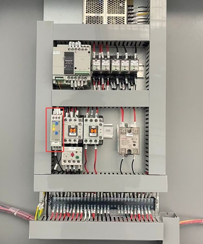
Figure 5
2.1.2 Grounding Requirements
The equipment must be reliably grounded, with a ground resistance of ≤4 Ω. Do not use gas pipes, non-metallic water pipes, or the neutral wire as a substitute for the ground wire. After grounding is complete, use Grounding Resistance Tester to measure the ground resistance. Power may only be applied after confirming that the resistance meets the requirements, to prevent electric shock, equipment malfunctions, or measurement errors caused by poor grounding.
2.1.3 Electrical Operation Contraindications
Before wiring, inspecting, or maintaining the equipment, you must turn off the circuit breaker on the back of the unit and disconnect the main power supply; confirm that there is no residual voltage before proceeding;
Do not operate the equipment’s power switch, touchscreen, or instrument buttons with wet hands to avoid the risk of electric shock;
Do not place any foreign objects (such as tools or paper) inside the electrical control cabinet to prevent dust or foreign objects from causing short circuits or damaging components;
Do not plug in or unplug power cords or signal cables while the equipment is running to prevent short circuits that could damage the controller or electrical components.
2.2 Operational Safety
2.2.1 Test Specimen Requirements
The equipment must not be used for testing hazardous materials. Since it is not equipped with explosion-proof devices, doing so may result in fire, explosion, or corrosion of the equipment;
The sample volume must not exceed 80% of the test chamber’s capacity. Do not block the dust outlet, and ensure the weight does not exceed the specified load capacity of the shelf (50 kilograms), to prevent deformation of the shelf or interference with the talc circulation.
2.2.2 Operating Procedures
In the event of equipment malfunction, non-professionals are prohibited from disassembling or repairing the equipment; please contact LISUN Customer Service or operate the equipment under the guidance of a technician;
When handling talcum powder, wear a dust mask to avoid inhaling it;
Do not open the chamber door during the test, as doing so will cause a large amount of talcum powder to escape from the test chamber;
If the equipment triggers an alarm, immediately stop the test and troubleshoot the problem. Do not force the equipment to restart (to prevent further damage).
2.3 Environmental Safety
2.3.1 Installation Requirements
The equipment must be installed in an air-conditioned room where the ambient temperature is maintained between 5°C and 25°C and the relative humidity is ≤85%. If the ambient humidity is high, condensation may form near the equipment door and test ports; in such cases, improve room ventilation or use a dehumidifier;
The installation site must be free of high concentrations of dust, corrosive gases (such as sulfur dioxide and chlorine), and flammable or explosive gases. Direct sunlight must not be allowed to shine on the equipment to prevent corrosion of the equipment housing and aging of electrical components;
2.3.2 Space Requirements
The distance between the equipment enclosure and the wall, as well as surrounding fixtures (such as other test equipment and shelves), must be at least 1500 mm to ensure unobstructed airflow through the equipment’s ventilation openings (on the back and sides);
At least 2000 mm of space must be left at the equipment door opening to ensure that the door can be opened in any direction, facilitating the placement and removal of samples;
2.3.3 Horizontal Placement
The equipment must be placed on a solid, level surface. Use a level to ensure the equipment is level: Place the level on the top surface of the equipment and confirm that the bubble is centered. Note: The test chamber’s legs are adjustable to ensure the chamber is level:
If the equipment is tilted, it may compromise the structural stability of the test chamber, cause uneven distribution of talcum powder inside the chamber, and even result in an uneven chamber door and poor sealing, which can affect test results and the equipment’s service life.
2.4 Other
For matters not covered in this manual, please proceed with caution or contact us.
3. Introduction to the Touchscreen Program
3.1 Introduction to the Program Interface
3.1.1 User Interface
| No. | Note |
| ① Load Power Supply | Turn the sample power on or off |
| ② Vacuum Pump | The vacuum pump can be turned on or off. IP5X generally does not require the vacuum pump to be turned on; IP6X generally requires the vacuum pump to be turned on. |
| ③ Lighting | Turn the lighting inside the test chamber on or off |
| ④ Reset | Click to reset the test timer and prepare for the next test. |
| ⑤ Start | Click to start the dust resistance test |
| ⑥ Stop | Click to stop the dust resistance test |
| ⑦ Time Display | Display the total duration of the current test |
| ⑧ Time Spent Away from the World | After entering the dust-removal cycle, display the current dust-removal duration |
| ⑨ Dust-settling time | After entering the dust-free cycle, the current duration of the dust-free cycle is displayed. |
| ⑩ Temperature Display | Display the current temperature inside the test chamber |
| ⑪Manual Window | Used to verify that all functions of the test chamber are operating normally, and to dry and clean the talcum powder inside the test chamber |
| ⑫ Parameter Settings | Used to set dust test parameters |
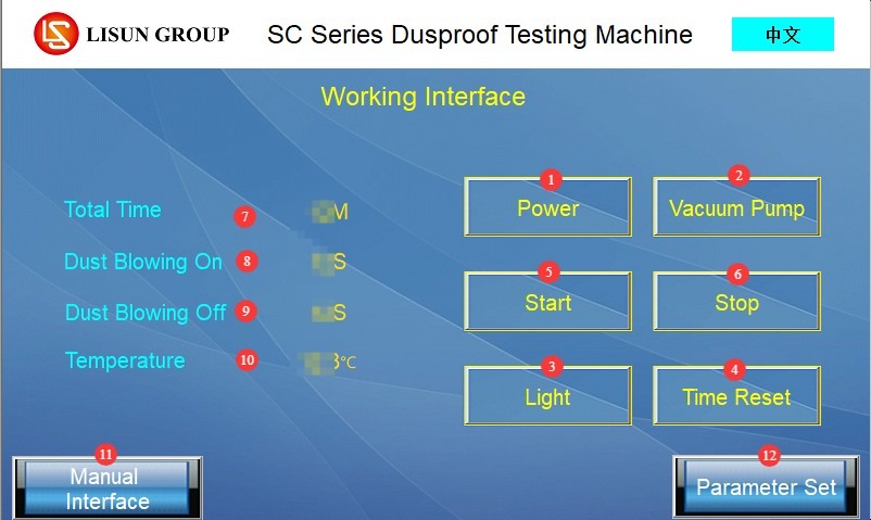
Figure 6
3.1.2 Manual Window
| No. | Note |
| ① Load | Turn the sample power on/off |
| ② Transcendence | Turn the fan on/off |
| ③ Vibration | Turn the vibration device on/off |
| ④ Heating | Once clicked, the test chamber will heat up to the set temperature to dry the talcum powder inside. Note: You must first click “Dust Removal and Vibration,” then click “Heating” to start the heating program. |
| ⑤ Vacuum Pump | Click to turn the vacuum pump on or off |
| ⑥Back | Click to return to the work interface |
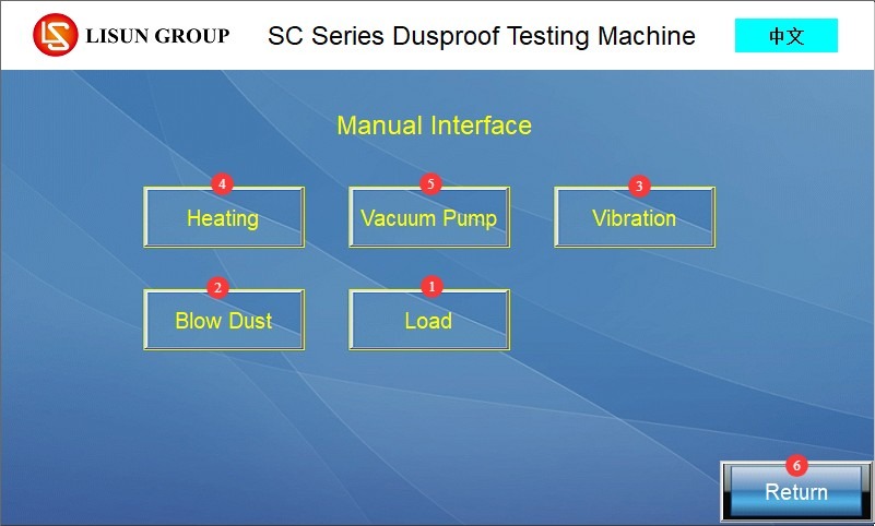
Figure 7
3.1.3 Parameter Settings Interface
| No. | Note |
| ① Total Test Time | Set the total duration of the test in minutes. |
| ② Time for “Escape from the Mundane” | Set the dust emission on/off times in seconds. When the test begins, dust emission will cycle according to the set times. Note: The system has been factory-calibrated and preset (30 seconds on, 150 seconds off); please do not change these settings. |
| ③ Time at the “Transcendence Pass” | |
| ④ Vibration On Time | Set the vibration on/off duration in seconds. When the test begins, the vibration will cycle according to the set duration. Note: The device has been factory-calibrated and preset (30 seconds on, 30 seconds off); please do not change these settings. |
| ⑤ Vibration Shutdown Time | |
| ⑥ Load On Time | Set the sample on/off times in seconds. When the test begins, the load sample will cycle on according to the set times. Note: If you want the sample to remain on continuously during the test, set the load on time to match the total test duration and set the load off time to 0. |
| ⑦ Load-off time | |
| ⑧ Temperature Setting | The temperature required for drying talc powder is generally set to 40°C. |
| ⑨ Temperature Control | It is preconfigured at the factory and requires no changes. |
| ⑩Back | Return to the Work Interface |
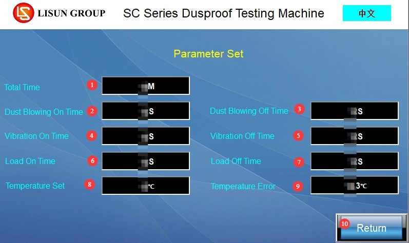
Figure 8
3.2 Description of the Program Alarm Interface
The test was not reset when it started. Please go back, click “Reset,” and then continue.
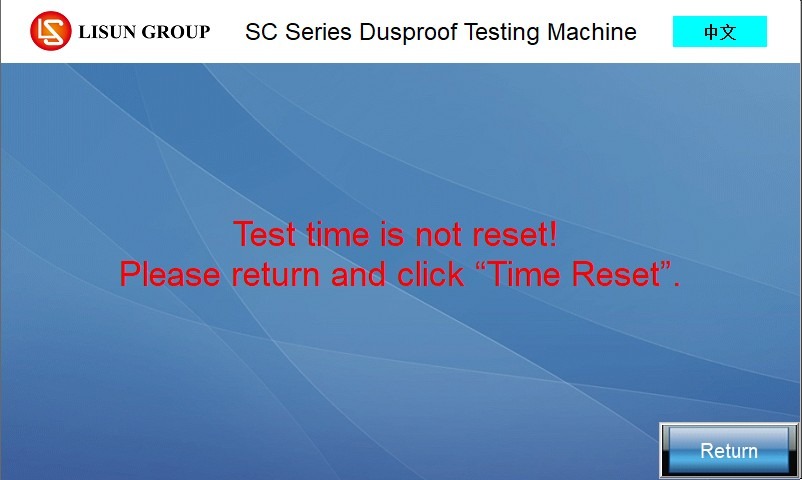
Figure 9
Emergency stop has not been reset. Please turn the emergency stop button clockwise to reset it.
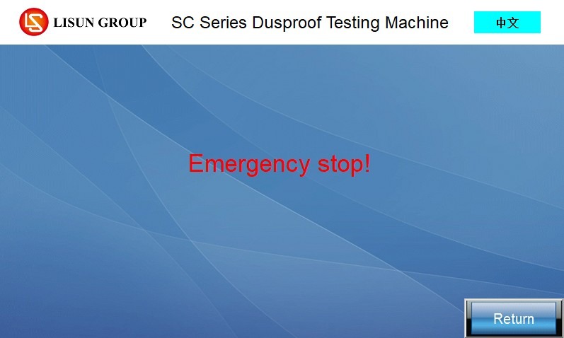
Figure 10
Thermal relay protection. Please turn off the power, wait 5 minutes, and then turn it back on. If the same alarm persists, please contact us.
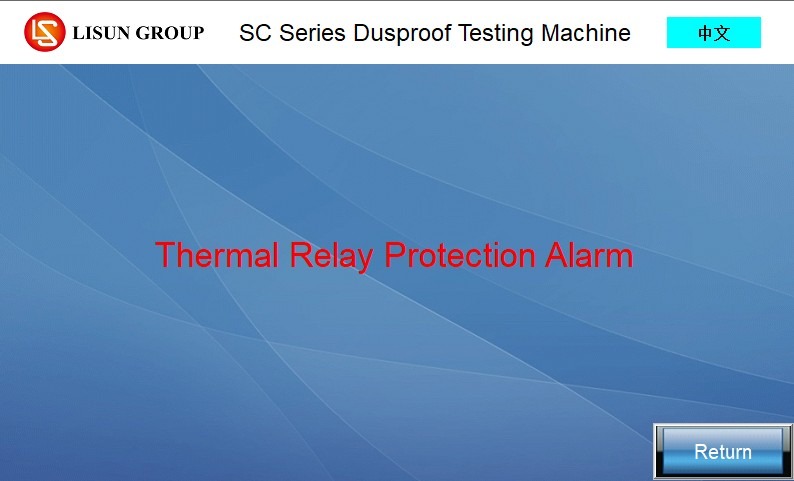
Figure 11
The test is complete. Click “Back” to continue.
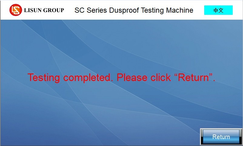
Figure 12
Phase Sequence Protection. When this alarm appears on the three-phase power test chamber, it indicates that the phase sequence of the incoming power to the test chamber is connected incorrectly. Shut down the unit, reconnect the power according to Section 2.1.1, and then restart it.
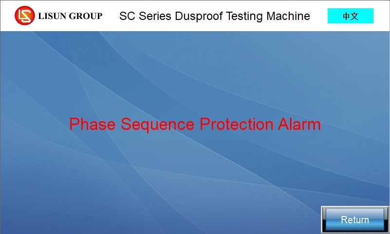
Figure 13
4. Preparations Before the Test
4.1 Sample Preparation
4.1.1 Determination of Sample Housing Type
According to Clause 13.4 of GB/T 4208-2017, sample enclosures are classified into two categories, and the classification result determines the test procedure. The key distinction is whether a vacuum test is required:
Class I Enclosures (Negative Pressure Type): During normal operation, the internal pressure of the enclosure is lower than the surrounding atmospheric pressure (e.g., due to thermal cycling effects); a vacuum pump must be connected to perform a negative pressure dust-proof test;
Type II Enclosure (Atmospheric Pressure Type): The internal pressure of the enclosure is equal to the surrounding atmospheric pressure; no vacuum pump is required, and it is used for atmospheric pressure dust-proof testing.
4.1.2 Sample Pretreatment
Clean the surface of the sample housing thoroughly to remove dust, oil, and water stains, ensuring that the housing is dry and free of contaminants; inspect the sample’s exterior to ensure there is no damage or deformation, and verify that components such as doors, ventilation openings, connectors, and shaft seals are properly installed and consistent with the actual operating conditions.
Provide a dedicated vent hole for Class I enclosure samples; the vent hole must be located immediately adjacent to the sample’s vulnerable components. If a dedicated vent hole cannot be provided, connect the vent tube to the sample’s cable entry point; keep all other holes in the sample (such as drain holes and other cable entry points) in their normal operational state.
4.2 Preparation of Consumables
4.2.1 Talc Powder Treatment
Take the medical-grade talcum powder intended for testing and thoroughly sieve it using the equipment’s standard sieve (wire diameter 50 μm, mesh size 75 μm) to remove lumps and impurities.
4.2.2 Addition of Talc Powder
Calculate the amount required according to the standard: Add 2 kg of talcum powder per cubic meter of the test chamber’s internal volume (add 4 kg for a 2000-liter internal volume);
Open the chamber door. There is a mesh screen at the bottom of the inner chamber to prevent an excessive amount of talc powder from entering the ductwork in a short period of time. Slowly pour the sifted talc powder onto the mesh screen at the bottom of the inner chamber. Then close the chamber door.
4.3 Drying Talc Powder
If the air is humid and the talcum powder has become damp, dry the talcum powder before conducting the test. Enter the manual mode window, and click “Dust Release,” “Vibration,” and “Heating” in that order. Run the test chamber for about half an hour to dry the talcum powder inside. Let it stand for about half an hour until all suspended dust inside the test chamber has settled, then open the chamber door to proceed to the next step.
5. Dust Resistance Test Procedure
5.1 Sample Placement and Connection
Open the device chamber door and place the pretreated sample in the center of the mesh metal divider inside the chamber; if placing multiple samples, maintain spacing between them—do not place them side by side in close proximity—to avoid interfering with the talc powder circulation;
Sample Connection (Select as Needed): For the power-on test, connect the sample wires to the sample power socket on the right side of the inner chamber, ensuring the connection is secure; for the negative pressure test (Class I enclosure), connect one end of the vacuum hose to the sample vacuum port/cable entry, ensuring the connection is properly sealed; Atmospheric Pressure Test (Class II Enclosure): No evacuation tubing is required; seal the end of the vacuum pump hose to prevent dust ingress.
Close the equipment cabinet door, check that there are no gaps in the door seal, and ensure that the test chamber is airtight.
5.2 Test Parameter Settings
Set the parameters according to the GB/T 4208-2017 standard and the sample type.
Total Test Duration: For Class I enclosures, start the vacuum pump, adjust the pressure control knob, and set the total test duration based on the pumping rate (which must not exceed 60 times the volume of the sample enclosure per hour). If the pumping rate is 40–60 times the volume per hour, the test duration is 2 hours; if the pumping rate is less than 40 times the volume per hour, the test duration is 8 hours; at no time shall the negative pressure differential exceed -2 kPa (as indicated by the pressure gauge); the test duration for Type II enclosures is 8 hours;
Load On/Off Time: If the sample is powered on throughout the entire test, the load on time equals the total test time, and the load off time equals 0; for intermittent power supply, set the times as required;
Temperature setting: 40°C; leave the temperature adjustment at the default value;
Keep the remaining parameters (related to dust discharge and vibration) at their factory default values; no changes are necessary.
5.3 Starting the Test
In the work interface, click “Lighting” as needed to turn on the interior lighting, which makes it easier to observe the test status. Click “Vacuum Pump” (select this for Class I enclosures; do not select for Class II enclosures) and “Load Power” (select this for powered tests; do not select for unpowered tests) as needed;
Click “Reset” to clear the record of the last test time;
After confirming that all settings are correct, click “Start” to begin the test. The timer will start on the touchscreen display, and the equipment will operate automatically according to the set parameters (dust generation, vibration, vacuum extraction, etc.).
5.4 Monitoring the Test Process
During the test, periodically check the equipment’s status: ensure that the touchscreen parameters show no abnormalities, the talcum powder suspension inside the chamber is normal, and there are no dust leaks, unusual noises, or smoke;
If a vacuum pump is running, monitor the pressure gauge and flowmeter in real time to ensure that the pumping speed and pressure differential remain stable. If fluctuations occur, adjust the pressure control knob slowly and promptly;
Inspect the condition of the sample: Ensure that the energized sample shows no signs of short circuits or tripping, and that the housing shows no deformation or cracks;
If any abnormalities occur, immediately press the emergency stop button or click the “Stop” button on the test interface. After troubleshooting the problem, decide whether to continue the test.
6. Post-Test Procedures
6.1 Test Termination Procedures
Once the test reaches the set total duration, or if the “Stop” button is manually clicked during the test, the equipment stops running, and all operating components (fan, vacuum pump, vibration mechanism, etc.) automatically shut down.
6.2 Sample Removal and Evaluation of Test Results
After the test is complete, let the equipment stand for 30 minutes to allow the talcum powder suspended inside the chamber to settle completely before opening the chamber door, to prevent the talcum powder from becoming airborne;
Open the chamber door, disconnect the sample’s power supply (if any) and the vacuum tubing (if any), and then carefully remove the sample;
Sample Inspection: Remove talcum powder from the sample’s surface and check whether any talcum powder has entered the interior of the housing; verify that all components of the sample are functioning properly and check for any malfunctions or damage caused by talcum powder.
| IP5X | IP6X |
| A small amount of non-hazardous dust is permitted to enter, provided that the amount of dust entering does not affect the normal operation or safety performance of the equipment; there is no significant dust accumulation, or any accumulated dust will not cause component damage, performance degradation, or affect electrical insulation; a negative pressure environment is generally not required during testing (except for special types of enclosures). | Under the specified test conditions, no dust shall enter the interior of the enclosure; observation under an optical microscope (200×) shall confirm the absence of visible dust particles; no dust shall be deposited on critical components (such as circuit boards, connectors, heat sinks, etc.). |
6.3 Dust Removal Procedure (to be performed after talcum powder has been used ≥20 times)
Open the “Manual” window in the touchscreen program and activate the vibration function to cause all the talcum powder to settle to the bottom of the inner chamber. Once there is no dust floating inside the test chamber, open the chamber door. If there is still talcum powder remaining on other parts of the inner chamber, use the provided brush to sweep it down to the bottom of the inner chamber.
Open the bottom access panel of the device (which may be located on the front or side). Use a wrench to loosen the mounting screws at the bottom of the inner chamber, allowing all the talcum powder to drain into the container, thereby completing the talcum powder cleanup. Then, reattach the bottom mounting screws and close the access panel.
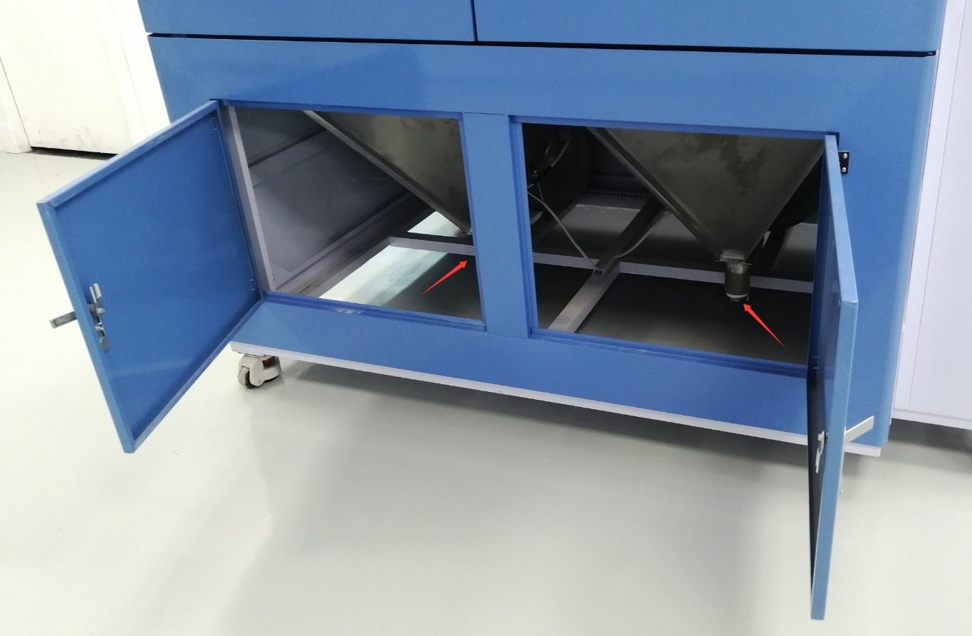
Figure 14
Note: Depending on the volume of the test chamber, the number of blowers and the number of large screws listed here may vary.
In accordance with the requirements in Section 4.2, add talcum powder again to complete the dust replacement.
6.4 Device Reset
Touchscreen Operation: Tap the “Reset” button on the test interface to clear all data from the current test and prepare for the next test;
Power Reset: If you will not be conducting any tests for a short period of time, press the power button on the front of the device to turn it off, and then turn off the main power supply at the circuit breaker on the back of the device.
7. Daily Maintenance and Care of Equipment
7.1 Routine Maintenance
After testing, promptly remove any talcum powder from the inner and outer chambers to prevent it from entering precision components such as the fan, vacuum pump, and electrical connectors, which could cause blockages or short circuits. Keep the equipment surface dry, clean, and free of dust and oil.
7.2 Regular Maintenance
7.2.1 Monthly Maintenance
If the equipment is left idle for an extended period, operate it once a month: Connect the power, enter the manual mode interface, and turn on the dust discharge, vibration, and heating functions in that order for 5–10 minutes to prevent components such as the fan, vacuum pump, and vibrator from seizing up or rusting, and to dry out any residual moisture inside the drying chamber.
7.2.2 Irregular Maintenance (Performed as Needed)
Talc Powder Filter Unit: After a period of use, open the unit and replace the internal filter cartridge to prevent talc powder buildup from reducing the vacuum pump’s suction efficiency or even causing damage to the vacuum pump;
Seals: Inspect the seals on the chamber door and the vacuum hose connections. If any are worn or damaged, replace them promptly to ensure the test chamber remains airtight and prevent dust from escaping during testing.
7.3 Consumables Management (Extending the Service Life of Consumables and Ensuring Test Accuracy)
Talcum powder: Use only the medical-grade talcum powder supplied with the equipment, and it must be sifted before use; if the talcum powder has absorbed moisture, it must be dried before use; do not use talcum powder that has clumped or deteriorated; talcum powder may be used no more than 20 times; replace it immediately once this limit is reached.
Screen: Regularly clean talc residue from the screen to prevent the mesh openings from clogging; if the screen becomes deformed or damaged, replace it promptly to ensure effective talc filtration.
Troubleshooting and Resolving Common Issues
| Fault Symptoms | Possible Causes | Procedure |
| When I press the start button, the test does not start. | The data from the previous test was not reset to zero. | Click the “Reset” button on the test interface to clear the historical test data, then restart the test. |
| When I press the “Heat” button, the test chamber does not heat up. | Did not first click “Out of the Mundane” and “Vibration” | First, select “Dust Removal and Vibration,” then select “Heating,” and the test chamber will begin the heating process to dry the contents. |
| During the test, some dust particles drifted out. | 1. The test chamber door is not closed tightly; 2. The test chamber door is misaligned; 3. The gasket is worn out | 1. Please close the test chamber door securely; 2. Please carefully check whether the test chamber door has shifted during transport, preventing it from closing properly, and adjust it as needed; 3. Please replace the gasket. |
| During the first-class enclosure test, after starting the vacuum pump, I adjusted the pressure control knob, but no negative pressure was generated. | Poor sample sealing performance | Set the test duration based on the pumping speed; no negative pressure is required. 2. If the sample is intended to be airtight, please recheck and improve the sample’s seal before retesting. |
| The test starts normally, but the fan does not rotate, and no talc powder is blown out of the dust outlet. | A large amount of talcum powder entered the blower duct in a short period of time, causing a blockage. | After shutting down the system, remove the corresponding fan and its ductwork, clear out all talcum powder from inside the ductwork and the fan, and then reinstall them; 2. If the fan still does not operate, it may have burned out due to a prolonged blockage; please replace the fan. |