
 English
 中文简体
中文简体 English
 Русский
 Español
 Português
 Türkçe
 العربية
 Deutsch
 Polski
 Italiano
 Français
 한국어
한국어 ไทย
ไทย Tiếng Việt
 日本語
日本語





























Lamp Cap Temperature Rise Test System
User's Manual
Applicable LISUN models: TMP-L、TMP-LB、TMP-LM、TMP-LS、TMP-LX1
1. Unboxing and Basic Familiarization with the Equipment
1.1 Key Technical Specifications
| LISUN Model | TMP-LS | TMP-LM | TMP-LB |
| Inner Dimensions (L x W x H) | 900 × 900 × 900 mm | 1200 × 1000 × 1800 mm | 1800 × 1800 × 1800 mm |
| External Dimensions (L x W x H) | 1200 × 1200 × 1150 mm | 1500 × 1300 × 1950 mm | 2100 × 2100 × 1950 mm |
| Interlayer spacing | 150 mm | ||
| Screen Mesh Aperture Size | 1–2 mm | ||
| Aperture Area | 40% ± 5% | ||
| Lamp Holder Model | Nickel-ring lamp holders: E14, E27, E40, and B22d (other sizes available upon request) | ||
1.2 Primary Purpose of the Equipment
This equipment is specifically designed for testing the temperature rise of lamp burners and lamp bases. Its core component, the windscreen, effectively prevents air convection from interfering with the test and isolates the test sample from the thermal radiation of the light source, providing a stable, standardized environment for testing lamp base operating temperature, ambient temperature, and temperature rise.
The equipment fully complies with GB/T 7000.1-2023 (IEC 60598:2024 Appendix D), QB/T 2512-2001, IEC 60360:1998, and other standards. It is suitable for testing the temperature rise performance of various types of luminaires and accessories, and serves as a key piece of equipment for luminaire safety certification and quality control.
1.3 Unboxing Inspection and Verification of Accessories
1.3.1 Unpacking and Visual Inspection
When unpacking the device, handle it gently to avoid scratching the casing with sharp tools. After unpacking, first inspect the exterior of the device to ensure there is no visible deformation or dents, and that the buttons are not damaged or loose. If you notice any abnormalities with the device or its accessories, do not turn it on. Please contact us immediately.
1.3.2 Main Unit and Accessories
TMP Windscreen:
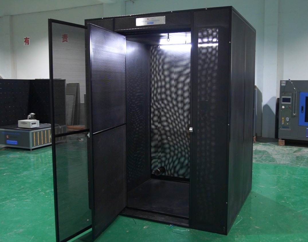
Figure 1
Nickel-band lamp bases: E14, E27, E40, and B22d:
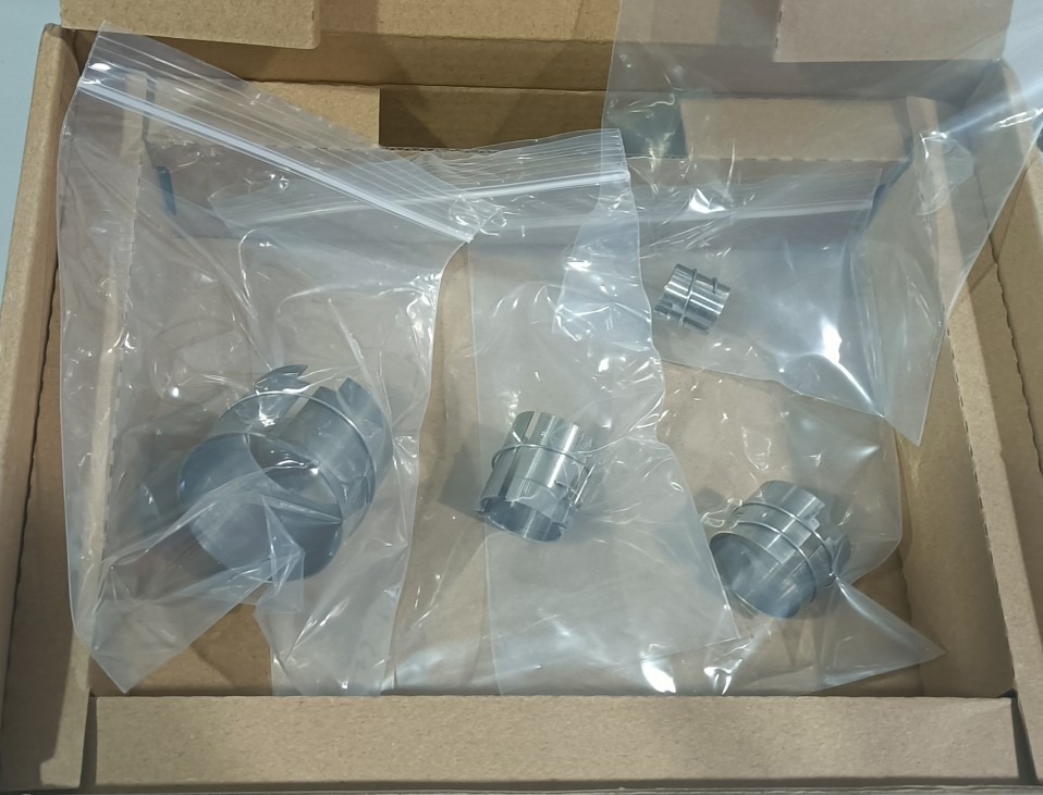
Figure 2
Multiplex Temperature Tester:
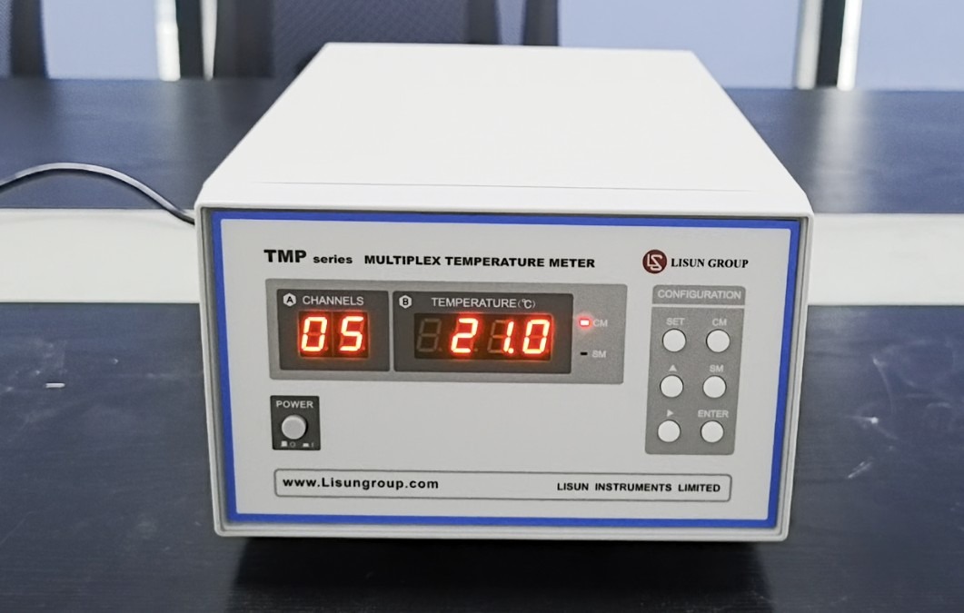
Figure 3
Note: The Multiplex Temperature Tester must be purchased separately; it is used to connect a Type K thermocouple to monitor the real-time temperature and temperature change curve of the sample inside the draft shield.
Download links for the digital user manual, software, warranty card, and other materials have been sent via email. Please download them as soon as possible. If you missed the email, please feel free to contact us to request the download links again.
1.4 Equipment Overview
1.4.1 Front of the Device
The front features a windshield cover door.
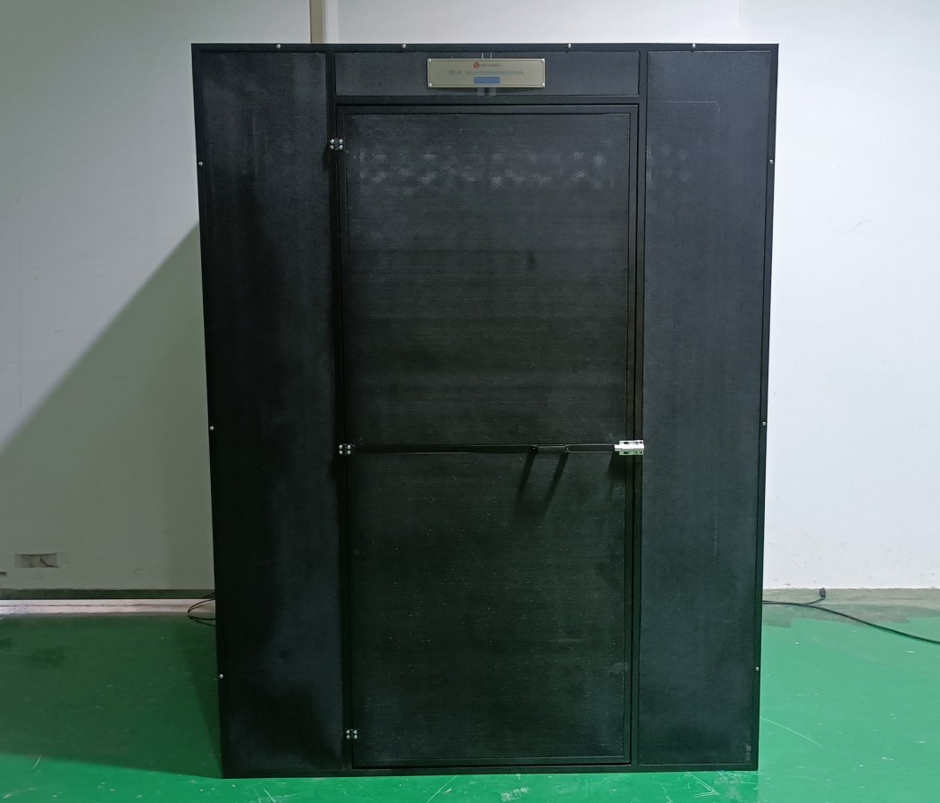
Figure 4
1.4.2 Back of the Device
| Number | Note |
| ① | Power cord, used to supply power to the light inside the windshield |
| ② | Cable holes for routing the sample lamp power cord and thermocouple wires through the windshield |
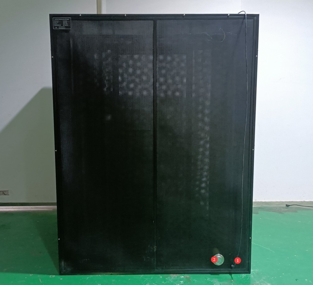
Figure 5
1.4.3 Inside the Equipment
| Number | Note |
| ① | Two lifting eyes, used for suspending samples |
| ② | Lighting Fixture |
| ③ | Light Switch |
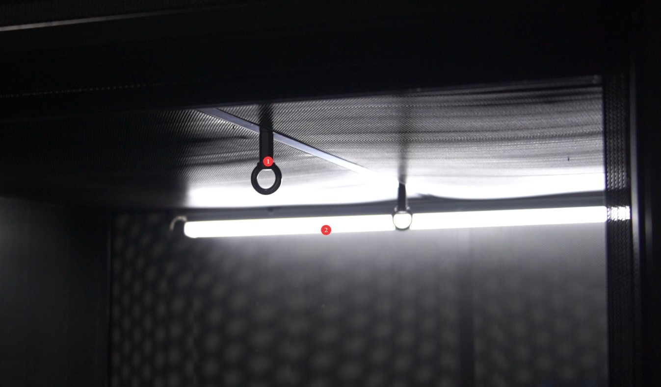
Figure 6
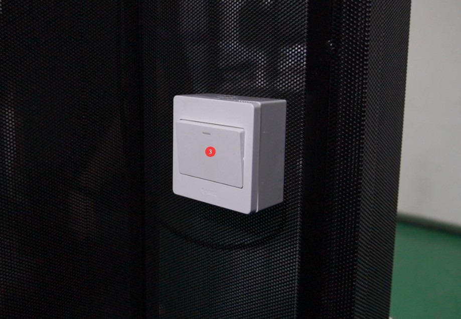
Figure 7
Note: The lighting is intended for use only prior to testing, to facilitate the installation of the test lamp and thermocouple. When preparing for the test, turn off the lighting first, then close the draft shield door before proceeding with the test.
2. Safety Precautions
2.1 Environmental Requirements
Ambient Temperature: When used indoors, maintain a temperature of 25°C ± 5°C. Avoid direct sunlight or placement near heat or cold sources.
Ambient humidity: ≤65% RH, with no condensation.
Ensure there is no noticeable air convection in the test area (e.g., close doors and windows; stay away from fans and air conditioning vents).
No flammable or explosive materials may be stored near the windscreen; the testing area must be equipped with fire extinguishers to prevent fires caused by lighting fixture malfunctions.
Space Requirements: Allow for ≥50 cm of working space around the equipment to ensure adequate ventilation; allow for ≥150 cm of working space in front of the equipment to facilitate opening the door.
Floor Requirements: The floor must be level to ensure that the windscreen remains stable at all times during operation and testing.
2.2 Operational Safety
Light fixtures generate high temperatures during testing. Operators must wear heat-resistant gloves to avoid direct contact with the glass envelope, lamp base, and test socket, and to prevent burns.
When installing or replacing a test specimen, ensure that the power is turned off and the lamp has completely cooled down. Under no circumstances should you adjust the position of the lamp or replace it while it is still powered on.
During testing, do not move the windscreen or open the windscreen enclosure door to prevent air convection from disrupting the test environment and affecting data accuracy, and to prevent burns from heat radiation.
3. Operating and Using the Windscreen
3.1 Sample Preparation
Select three light fixtures of the same model.
Inspect the appearance of the test specimen to ensure there are no cracks, deformations, loose parts, or rust, and that the light fixture functions properly.
Record the rated voltage, wattage, and base type (e.g., E14, E27) of the light fixture to ensure that the base matches the model of the test nickel-ring lamp holder.
3.2 Connecting a Typical Sample
In accordance with standard QB/T 2512-2001. The typical relationship between a nickel-ring lamp holder and a screw-in lamp base is shown in the figure below.
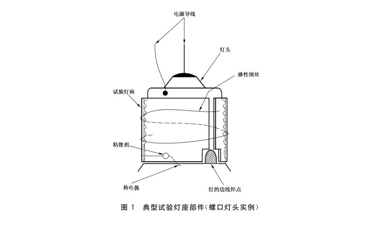
Figure 8
Power cord material: copper; dimensions: effective cross-sectional area of 0.56 mm² to 0.71 mm² (equivalent to a solid-core wire with a diameter of 0.85 mm to 0.95 mm); Length: approximately 110 mm; the wire soldered to the hole in a bayonet lamp holder, or to the center contact of a screw-type lamp holder or a single-contact bayonet lamp holder, shall be solid; the multi-strand flexible wire connected to the test lamp holder shall be connected to the neutral wire of the power supply.
The typical relationship between the nickel-ring lamp holder and the thermocouple is shown in the figure below.
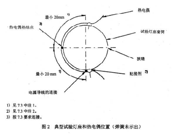
Figure 9
3.3 Light Fixture Installation
Hang the connected sample at the center of the draft shield; the clearance between the inner surface of the draft shield and any part of the light fixture should be at least 200 mm.
For luminaires mounted directly to ceilings or walls, they must be secured to a mounting surface made of wood or wood fiberboard. If the luminaire is not suitable for installation on a combustible surface, a mounting plate made of non-combustible insulating material must be used. The board should be 15 mm to 20 mm thick, with dimensions at least 100 mm larger than the vertical projection of the luminaire’s outer contour (though preferably no more than 200 mm). The gap between the board and the inner surface of the windscreen must be at least 100 mm. The board must be painted black with a matte, non-metallic paint.
For further details, refer to Appendix D of GB/T 7000.1-2023 (IEC 60598:2024).
3.4 Method for Measuring the Temperature Rise of a Lamp Base
Light the lamps at 1.06 times the rated voltage. Before measurement, each lamp shall be turned on and allowed to operate continuously for at least 30 minutes. A series of initial measurements may then be taken to verify that the temperature is no longer rising. When the equilibrium temperature is reached, record the ambient temperature of the test lamp holder and the test chamber. For each lamp, the measurement result shall be the nearest whole value in degrees Celsius.
Use high-temperature-resistant adhesive to secure the thermocouple probe of the Multiplex Temperature Tester firmly against the designated measurement surface of the lamp base (such as the top flat surface of an E27 screw base), ensuring that the probe makes full contact with the measurement surface without any gaps.
Take another thermocouple and secure it at the same height as the center of the luminaire, at a distance of at least 50 mm from both the luminaire and the wall of the windscreen, to measure the ambient temperature. The insulated portion of the thermocouple wires should extend all the way to the junction, and the wires should extend parallel to the bottom edge of the luminaire for at least 20 mm.
For further details, please refer to clause 12.4 of GB/T 7000.1-2023 (IEC 60598:2024).
3.5 Stability Assessment and Data Recording
3.5.1 Stability Assessment
Continuously monitor the temperature data; when the lamp base temperature varies by ≤1°C for 30 consecutive minutes, the temperature rise is deemed stable.
Record the lamp head temperature (T1) and ambient temperature (T2) under steady-state conditions, calculate the temperature rise ΔT = T1 – T2, and round the result to the nearest degree Celsius.
If any abnormalities occur with the luminaire during testing (such as the light going out, damage, or smoke), immediately disconnect the power supply, record the abnormality, and terminate testing of that sample.
3.5.2 Data Storage
Use a Multiplex Temperature Tester to record a complete temperature curve, noting the test specimen information (model, rated voltage, power, lamp base type), test environment parameters (temperature, humidity), and test duration.
Repeat the above steps to complete testing on the three specimens, and record the test data for each specimen separately.
3.6 Evaluation of Results
3.6.1 Conformity Assessment
If the temperature rise ΔT of all three test specimens is ≤ the standard limit for the corresponding lamp base (e.g., ≤ 120 K for an E27 lamp base), and the deviation among the three sets of data is ≤ 5 K, the temperature rise test for that lamp model is deemed to have passed.
Standard limits must strictly comply with the requirements of relevant standards, such as QB/T 2512-2001 and GB/T 7000.1-2023, and specific limits must be determined based on the type of lamp base.
3.6.2 Determination of Nonconformity
If the temperature rise of one or more test specimens exceeds the limit, or if the deviation between the data of three specimens is greater than 5 K, three new test specimens of the same model must be selected for retesting.
If the same situation occurs during the retest, the temperature rise test for that model of luminaire shall be deemed unsatisfactory.
4. Routine Maintenance and Care of Equipment
After the test is complete, disconnect the power supply to the equipment and associated instruments. Once the equipment has cooled to room temperature, use a clean, soft cloth to wipe down the draft shield housing, lamp holder, bracket, and other components to remove surface dust and stains.
Check whether the small holes in the windshield mesh are clogged; if there is a small amount of dust, gently brush it away with a soft-bristled brush. Check the nickel-plated lamp holder sleeve and the spring wire to ensure there is no debris and that the contact is good.
Organize the thermocouple wires to prevent tangling or pulling; check that the insulation is intact and that there are no loose solder joints.