
 English
 中文简体
中文简体 English
 Русский
 Español
 Português
 Türkçe
 العربية
 Deutsch
 Polski
 Italiano
 Français
 한국어
한국어 ไทย
ไทย Tiếng Việt
 日本語
日本語





























Withstanding Voltage & Insulation Test
User's Manual
Applicable LISUN models: LS9923
1. Unboxing and Basic Familiarization with the Equipment
1.1 Key Technical Specifications
| Parameters | Note | |
| AC and DC Withstand Voltage Testing | Output Voltage Range | AC/DC 0–5.00 kV |
| Output Voltage Accuracy | ±(3% + 3 digits) | |
| Breakdown Current Range | AC: Max 20 mA; DC: Max 10 mA | |
| Test Time | 0–999.9 s | |
| Output Frequency | 50 Hz/60 Hz | |
| Insulation Resistance Test | Output Voltage Range | DC 0–1.00 kV |
| Output Voltage Accuracy | ±(2% + 3 digits) | |
| Insulation Resistance Range | 1.0–2000 MΩ | |
| Insulation Resistance Accuracy | ±(5% + 3 digits) < 100 MΩ and ±(10% + 5 digits) > 100 MΩ | |
| Test Time | 0–999.9 s | |
1.2 Unboxing Inspection and Verification of Accessories
1.2.1 Unpacking and Visual Inspection
When unpacking the device, handle it gently to avoid scratching the exterior casing with sharp tools. After unpacking, first inspect the exterior of the device to ensure there is no visible deformation or dents, and that the buttons are not damaged or loose. If you notice any abnormalities with the device or its accessories, do not turn it on. Please contact us immediately.
1.2.2 Main Unit and Accessories
Host: 1 LS9923 host.
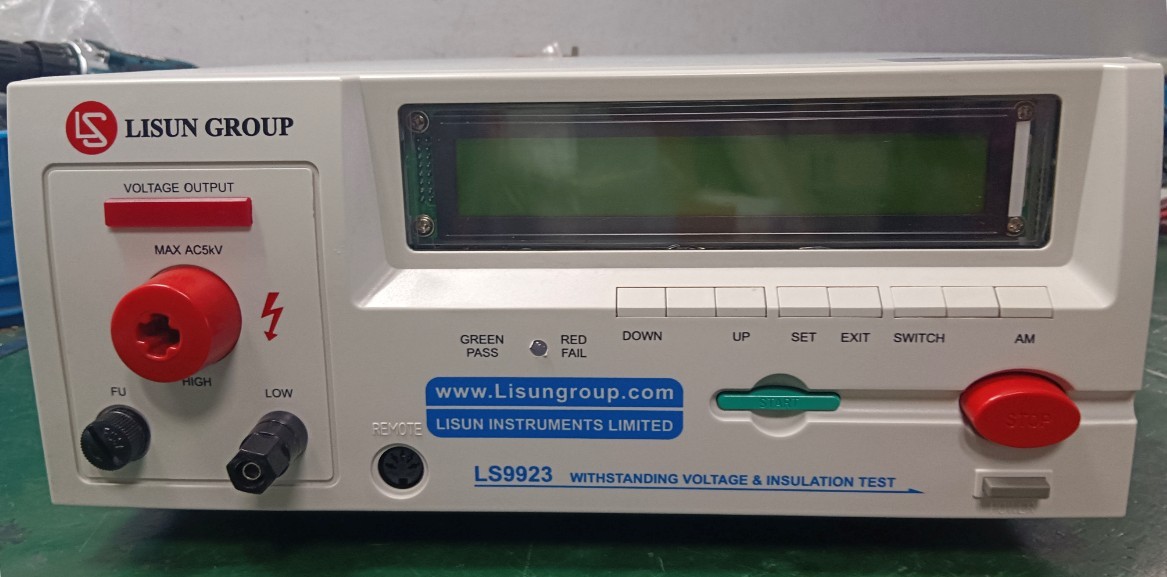
Figure 1
The main components are as follows:
| Number | Note |
| ① | Power Cord |
| ② | High-voltage rod, including high-voltage rod connection cable and remote control cable; the handheld end of the high-voltage rod includes control buttons |
| ③ | Grounding Clamp |
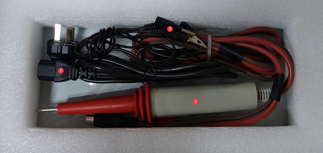
Figure 2
Download links for the digital user manual, software, warranty card, and other materials have been sent via email. Please download them as soon as possible. If you missed the email, please feel free to contact us to receive the download links again.
2 Safety Precautions
2.1 Electrical Safety
2.1.1 Power Supply Requirements
Use a single-phase AC 220 V ±10%, 50/60 Hz three-prong outlet; the ground prong must be connected to ground.
2.1.2 Grounding Requirements
The instrument ground wire is reliably connected to the protective ground wire, and the protective ground resistance is ≤4 Ω;
Do not short-circuit the output terminal to the AC power source to prevent the enclosure from becoming energized.
2.2 Environmental Safety
2.2.1 Temperature and Humidity Requirements
Avoid using the device in environments where humidity exceeds 70% (without condensation) or where temperatures fall outside the range of 0–35°C. The optimal operating temperature is 25 ± 2°C.
2.2.2 Environmental Contraindications
Environments with strong magnetic fields and strong electric fields;
Environments containing corrosive gases or liquids;
Areas with flammable and explosive dust, and locations containing hazardous materials;
Environments with heavy dust, high temperatures and humidity, and direct sunlight.
2.3 Operational Safety
During testing, the outer casing of the test object is electrically charged; do not touch it with your bare hands under any circumstances;
The test specimen must be placed on a rubber insulating mat;
Operators must wear rubber insulated gloves;
Operators must have dry hands and must not wear metal jewelry; eating or drinking is prohibited during testing to prevent accidents caused by electric shock;
Before replacing the test object, you must first stop the test and disconnect the test object from the input power supply;
When multiple people are involved, clearly define roles and responsibilities, and confirm them with one another before testing begins to avoid errors.
2.4 Other
For matters not covered in this manual, please proceed with caution or contact us.
3. Equipment Operation
3.1 Parameter Settings
3.1.1 Prerequisites
To ensure operational safety, parameter settings cannot be made while the high-voltage rod and remote control cable are connected to the device. Please remove the high-voltage rod and remote control cable before configuring the parameters.
3.1.2 Setting Test Parameters in Automatic Mode
| Number | Note |
| ① | Press the AM button to switch the device to automatic mode. |
| ② | Test groups marked with an asterisk after the letter are in manual mode; those without an asterisk are in automatic mode. |
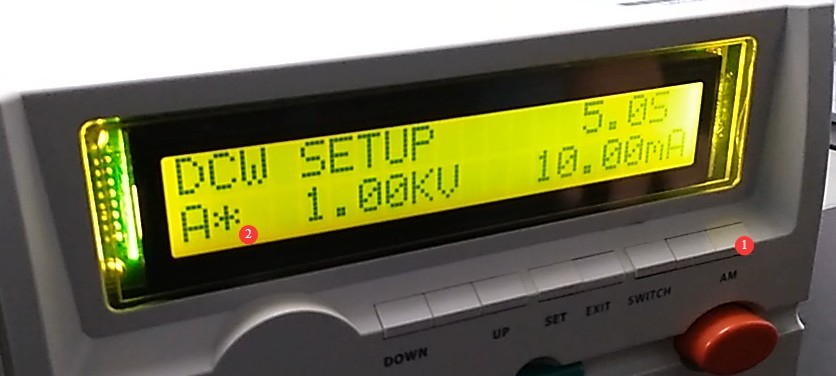
Figure 3
| Number | Note |
| ① | Use the up and down arrows to switch between test groups. |
| ② | Up to seven sets of test parameters (A through G) can be saved. For each set, different parameters can be configured to perform ACW (AC Withstand Voltage)/DCW (DC Withstand Voltage) and IR (Insulation Resistance) tests. Note: Only one of ACW or DCW can be selected within the same test set; if both are selected, only DCW and IR will be performed during actual operation. |
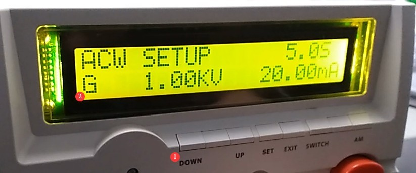
Figure 4
| Number | Note |
| ① | Press the SET button |
| ② | Use the up and down arrows to select a test item. |
| ③ | ACW, DCW, and IR |
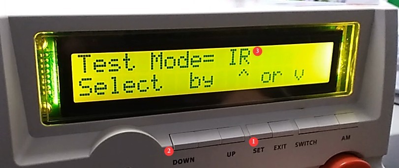
Figure 5
After selecting IR, press the SET button again to configure the IR test parameters. Note: All specific parameters can be set using the up and down buttons. Once a parameter is set, press the SET button again to configure the next item.
Test voltage settings.
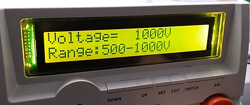
Figure 6
Setting the upper limit.
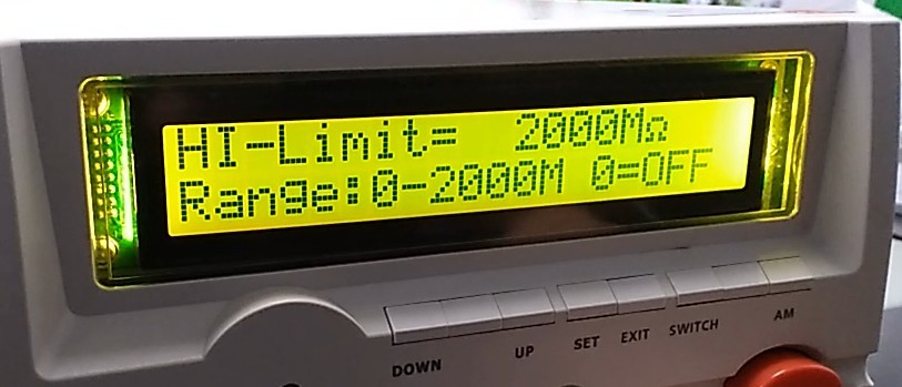
Figure 7
Lower limit setting.
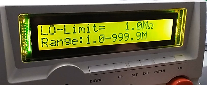
Figure 8
Test Duration Settings.
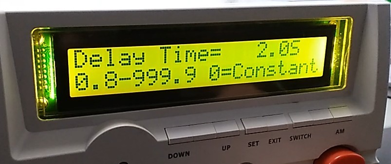
Figure 9
Sound Alert Settings.
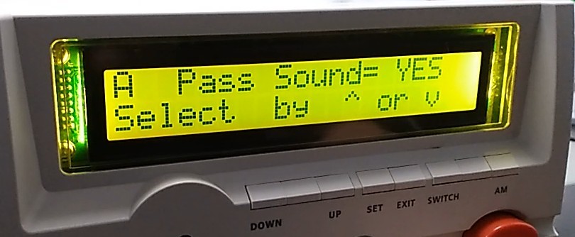
Figure 10
Select whether to run the IR test.
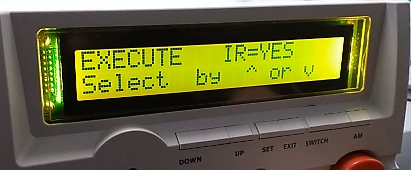
Figure 11
Switch the test mode to ACW.
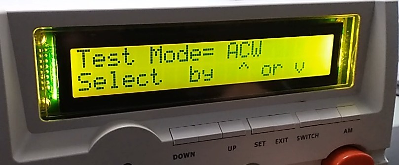
Figure 12
Test Voltage Settings.
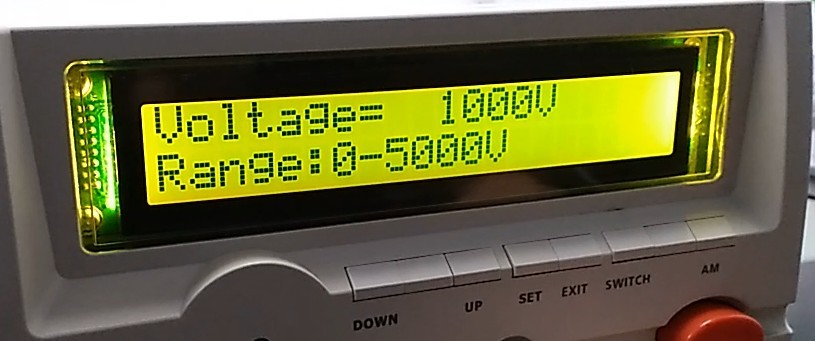
Figure 13
Setting the upper limit.
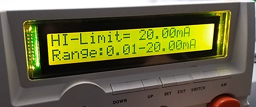
Figure 14
Lower limit setting.
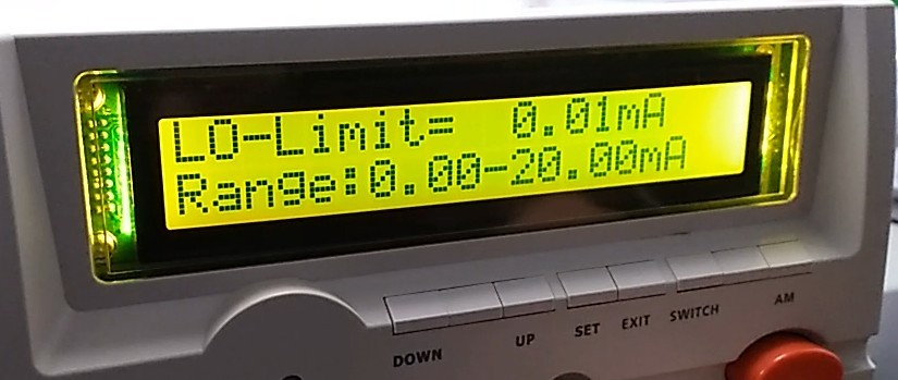
Figure 15
Rise time setting: the time required for the test voltage to rise from 0 to the set value.
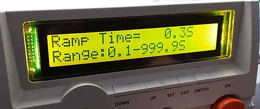
Figure 16
The test took a long time.
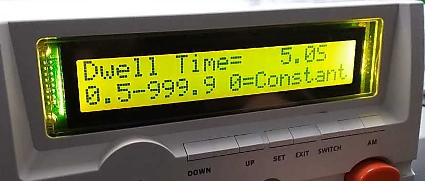
Figure 17
Frequency settings.
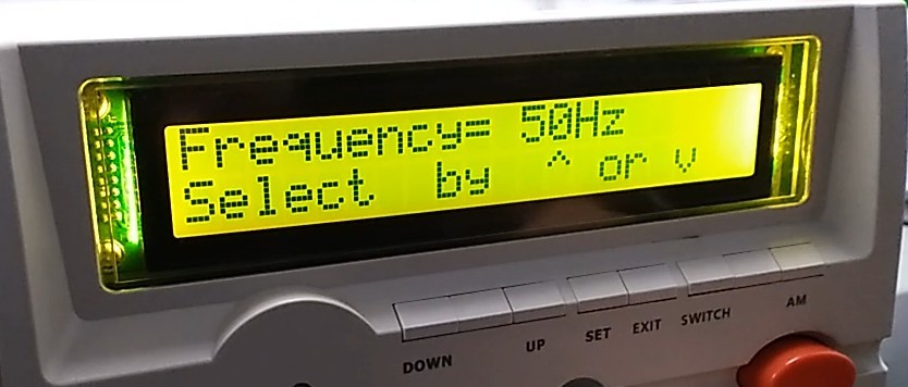
Figure 18
Arc detection function. 0 means no detection; 0 through 9 indicates detection sensitivity ranging from low to high.
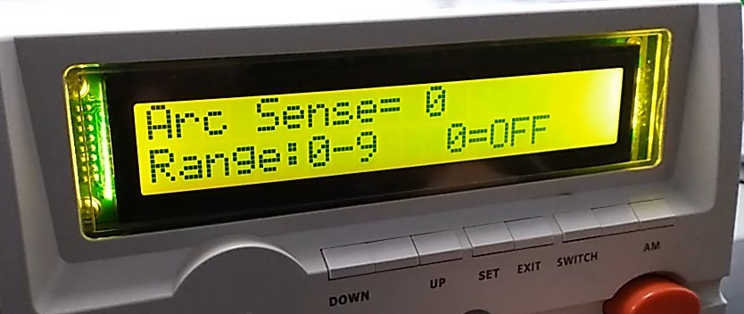
Figure 19
Sound Alert Settings.
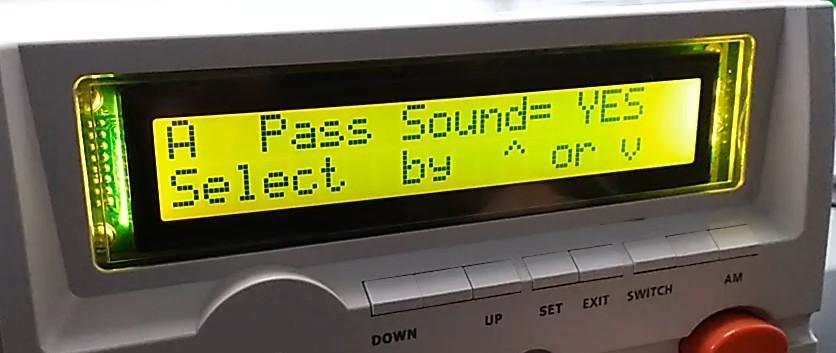
Figure 20
Select whether to run the ACW test.
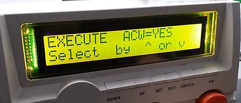
Figure 21
Switch the test mode to DCW.
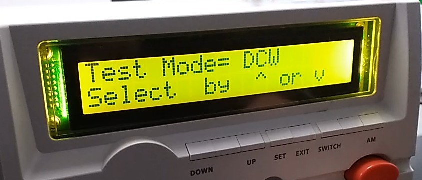
Figure 22
Test Voltage Settings.
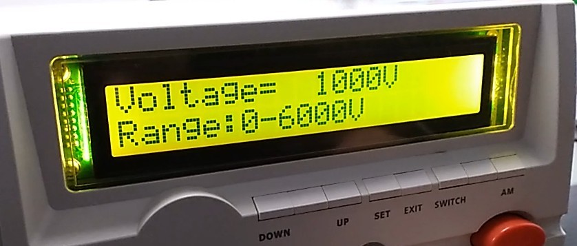
Figure 23
Setting the upper limit.
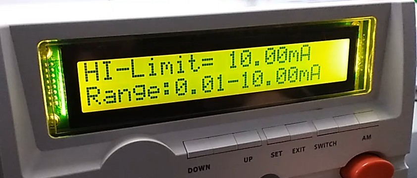
Figure 24
Lower limit setting.
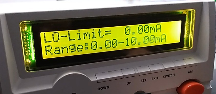
Figure 25
Rise time setting: the time required for the test voltage to rise from 0 to the set value.
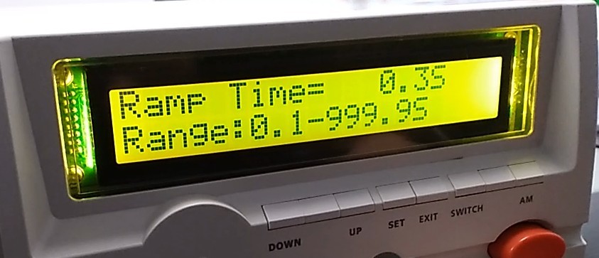
Figure 26
Test Duration Settings.
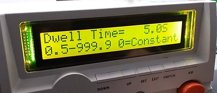
Figure 27
Arc detection function. 0 means no detection; values from 0 to 9 indicate detection sensitivity ranging from low to high.
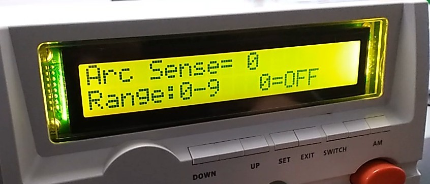
Figure 28
Sound Alert Settings.
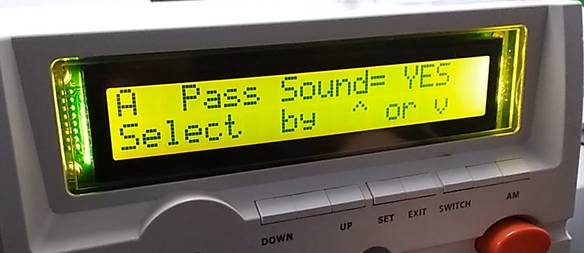
Figure 29
Select whether to run the DCW test.
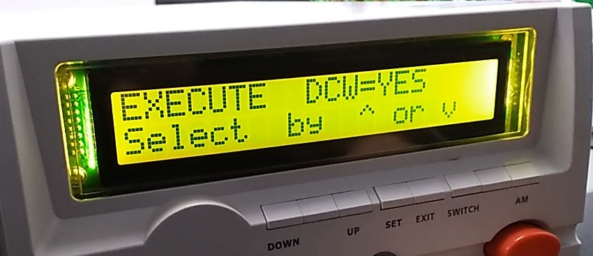
Figure 30
Once all settings are complete, press EXIT to return to the initial screen.
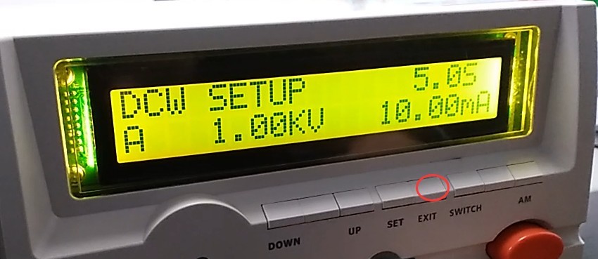
Figure 31
Note: Using GB/T 7000.1-2023 as an example, the following settings can be configured.
| Test Items | Corresponding Standard Provisions | Test Parameter Settings | Acceptance Limits | Test Time |
| Insulation Resistance Test | 10.2 | Test Voltage: 500 V DC | ≥2 MΩ | 60s |
| Dielectric Strength (Withstand Voltage) Test | Test Voltage: 1500 V AC | No breakdown, no flashover; leakage current ≤ 5 mA |
3.1.3 Introduction to Manual Mode
If the current test group is A, press the AM key to switch to Manual Mode A*. Manual Mode A* runs only the current test in test group A. If it is an IR test, press the SWITCH key to switch to ACW/DCW testing (provided that test group A is configured to perform ACW/DCW and IR tests simultaneously). Test parameters cannot be modified in manual mode; only the SWITCH and AM keys are available.
That is: In automatic mode, when a test is run, all test items configured in that test group are executed sequentially; in manual mode, when a test is run, only the current test item in that test group is executed.
3.2 Operational Testing
3.2.1 Front Panel Overview and Wiring
| Instructions | Note |
| ① | First, connect the ground clamp cable. |
| ② | Reconnect the remote control cable |
| ③ | Finally, connect the high-voltage rod cable |
| ④ | Start button—press to begin the test |
| ⑤ | Stop button: Press to stop the test |
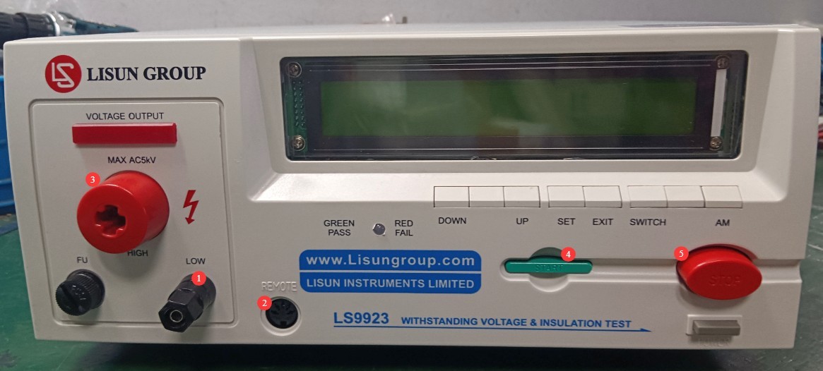
Figure 32
Note: Once the remote control cable is plugged in, the Start and Stop buttons on the device’s front panel will be disabled.
3.2.2 Connecting the Test Object
The test object’s casing must be clean and free of oil; place it in the center of the insulating mat, away from the metal work surface.
Taking a light fixture as an example, attach the grounding clamp to the fixture’s ground wire, and use the high-voltage tester to test the fixture’s power line (L or N).
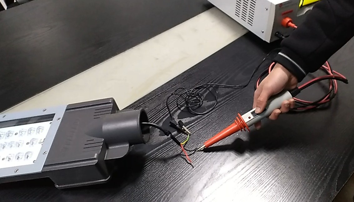
Figure 33
3.2.3 Startup Test
Press the Start button or the control button on the high-voltage probe to start the test; press the Stop button or release the control button on the high-voltage probe to stop the test.
3.2.4 Viewing Test Results
If the test continues until it completes normally, it is considered passed. If any single test item fails, the test stops automatically, and the screen displays the failed test item. Please check whether the issue is due to the parameter settings or the test specimen itself.
4. Daily Maintenance and Care of Equipment
4.1 Routine Maintenance
Before powering on, inspect the equipment to ensure it is clean and free of damage, that the cables show no signs of aging or breakage, and that the connectors are secure; Check the grounding clamps for oxidation or burn marks; if present, wipe them with a specialized contact cleaner, and contact us to replace parts if necessary; after testing is complete, disconnect the power and wipe the equipment surface and test area with an anti-static, dry cloth.
4.2 Long-Term Storage
When the device is not in use for an extended period, store it in a dry, well-ventilated area, away from moisture and direct sunlight; disconnect all cables, store accessories separately, and cover the device with a dust-proof cloth; turn on the device for 30 minutes each month to prevent the internal electronic components from deteriorating.
5. Troubleshooting and Resolving Common Problems
| Fault Symptoms | Possible Causes | Procedure |
| The device won’t turn on | The power cord isn’t plugged in securely; the fuse has blown. | Check the power cord connections; check the fuse in the device’s power input port; if it is blown, replace it with a fuse of the same model. |
| Some buttons aren’t responding | The device is in an inappropriate test mode | In Auto mode, the SWITCH button is unavailable; in Manual mode, only the SWITCH and AM buttons are available. |