
 English
 中文简体
中文简体 English
 Русский
 Español
 Português
 Türkçe
 العربية
 Deutsch
 Polski
 Italiano
 Français
 한국어
한국어 ไทย
ไทย Tiếng Việt
 日本語
日本語





























Immersion Tank Waterproof Test Device
User's Manual
Applicable LISUN models: JL-8
1. Unboxing and Basic Familiarization with the Equipment
1.1 Key Technical Specifications
| Parameters | Note |
| Diameter | 600 mm |
| Height | 1200 mm |
| Simulated water depth | 0–50 m |
| Work-related stress | Maximum test pressure: 0.5 MPa (equivalent to a water depth of 50 m) |
| Equipment Power Supply | Single-phase 220 V/50 Hz (60 Hz available upon request) |
Note: The diameter and height of the test tank can be customized based on the maximum dimensions and weight of the test item.
The device complies with the test requirements for IPX8 specified in Section 14.2.8 of GB/T 4208-2017.
1.2 Unboxing Inspection and Verification of Accessories
1.2.1 Unpacking and Visual Inspection
When unpacking the device, handle it gently to avoid scratching the casing with sharp tools. After unpacking, first inspect the exterior of the device to ensure there is no visible deformation or dents, and that the buttons are not damaged or loose. If you notice any abnormalities with the device or its accessories, do not turn it on. Please contact us immediately.
1.2.2 Main Unit and Accessories
| No. | Note |
| ① | IPX8 Immersion tank Waterproof test Device |
| ② | Ladder, for easy retrieval and placement of samples |
| ③ | Water hose, can be connected to the inlet/outlet |
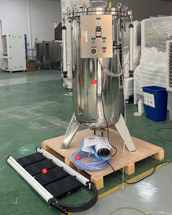
Figure 1
Note: The JL-8 unit requires an air compressor for operation; an air pressure of at least 0.8 MPa is sufficient.
Download links for the electronic user manual, software, warranty card, and other materials have been sent via email. Please download them as soon as possible. If you missed the email, you may contact us to request the download links again.
2. Safety Precautions
2.1 Electrical Safety
2.1.1 Power Connection Specifications
Based on the nameplate, connect the test chamber to the correct power source, typically 220 V, 50 Hz (60 Hz available upon request), and ensure the voltage and frequency are correct. Please use a dedicated circuit to avoid sharing the circuit with other high-power equipment. Verify that all connections are secure and free of looseness.
2.1.2 Grounding Requirements
The test chamber must be reliably grounded, with a grounding resistance of ≤4 Ω. Do not use gas pipes, non-metallic water pipes, or the neutral wire as a substitute for the grounding wire. After grounding is complete, use the Grounding Resistance Tester to measure the ground resistance. Power may only be applied after confirming that the resistance meets the requirements, to prevent electric shock, test chamber malfunctions, or measurement errors caused by poor grounding.
2.1.3 Electrical Operation Contraindications
Before wiring, inspecting, or maintaining equipment, the main power supply must be disconnected, and operations may only begin after confirming that there is no residual voltage;
Do not operate the test chamber’s power switch, touchscreen, or instrument buttons with wet hands to avoid the risk of electric shock;
Do not place any foreign objects (such as tools or paper) inside the electrical control cabinet to prevent dust or foreign objects from causing short circuits or damaging components;
Do not plug in or unplug power cords or signal cables while the equipment is running to prevent short circuits that could damage the controller or electrical components.
2.2 Environmental Safety
Sufficient clearance should be maintained between the unit and walls and surrounding equipment (such as other test equipment and shelving) to allow for easy operation and maintenance;
The equipment must be placed on a solid, level surface. Use a level to ensure it is level, making sure the bubble is centered. If the equipment is tilted, it may cause test abnormalities or even damage the equipment.
2.3 Safety Guidelines for Operation
2.3.1 Safety During Pressurization Operations
Monitor the pressure in real time during the pressurization process; if there is a sudden pressure spike or unusual noise from the tank, immediately press the stop button and vent the pressure;
Do not touch the cover plate, latches, or pneumatic fittings while under pressure to prevent injuries from high-pressure gas leaks;
Do not leave the work site until the pressure reaches the set value to ensure that any unexpected situations can be handled promptly.
2.3.2 Safety Precautions for Opening the Lid
Pressure must be relieved before opening the cover. Strictly follow the procedure: “Open the vent valve → Confirm that the pressure has returned to zero → Release the latch → Open the cover.” Do not force the cover open, to prevent high-pressure gas from blowing the cover off and causing an accident;
Do not place any objects or allow anyone to stand within the switch area under the cover plate to prevent accidental injury.
2.3.3 Safety Precautions for Handling Samples
Handle the sample with care when placing it in the water tank to prevent damage to the tank and the liquid level gauge assembly;
The sample must be completely submerged in water; it must not be partially exposed above the water surface to ensure the validity of the test;
When the sample floats to the surface, attach a counterweight. Ensure the counterweight is securely fastened; do not place it directly on the bottom of the tank, as this may damage the tank.
2.4 Other
For matters not covered in this manual, please proceed with caution or contact us.
3. Connecting the Equipment
3.1 Air Compressor Connection
| No. | Note |
| ① Compressed Air Inlet | Connect the Air Compressor |
| ② Pressure-regulating valve | After removing it, adjust the inlet pressure to approximately 0.8 MPa. Once adjusted, push the pressure regulator back into place. Note: When simulating a water depth of 50 meters, the required pressure is 0.5 MPa. |
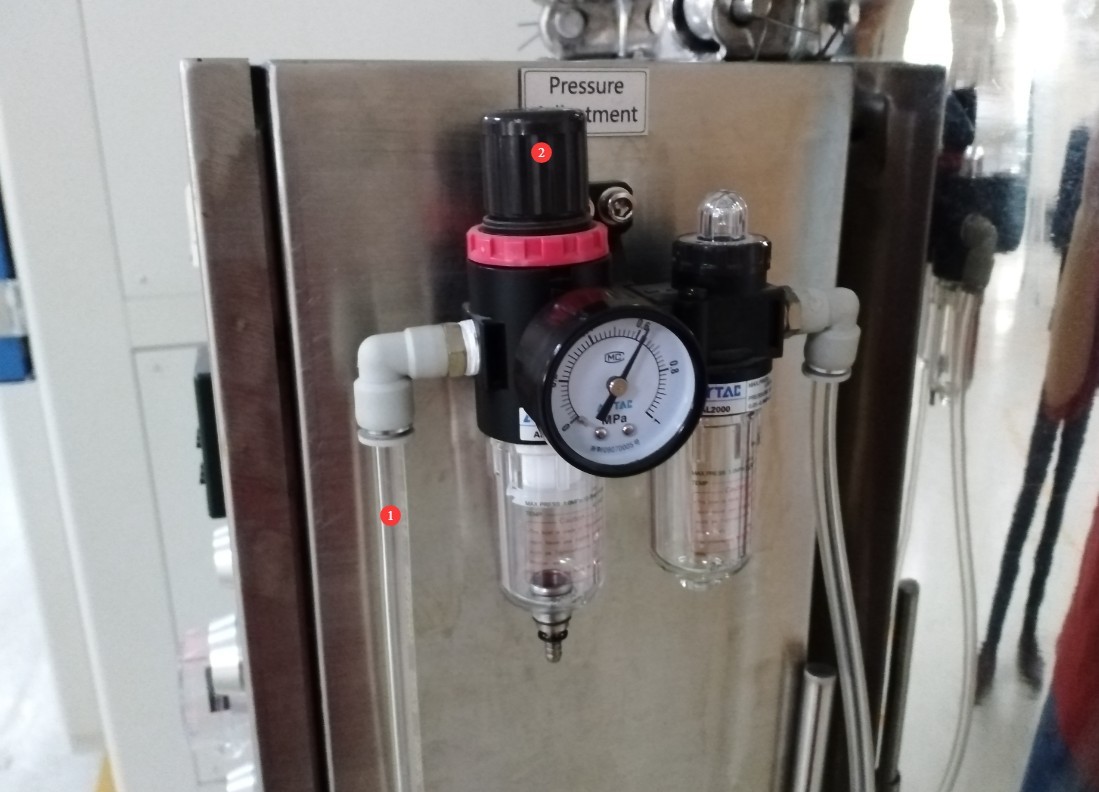
Figure 2
3.2 Water Pipe Connections
You can use the two valves at the bottom of the unit. Use one as the water inlet and the other as the drain outlet. Connect the inlet to a faucet and the outlet to a drain. To fill the unit, open the inlet valve and close the outlet valve; once filling is complete, close the inlet valve. To drain the unit, open the outlet valve and close the inlet valve; once draining is complete, close the outlet valve.
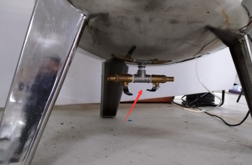
Figure 3
Note 1: The valve is closed when the handle is perpendicular to the water pipe, and open when it is parallel to the pipe.
Note 2: During the test, both valves must be in the closed position.
3.3 Power Cord Connection
| No. | Note |
| ① Power cord | Please connect the device to the correct power source according to the information on the nameplate. |
| ② Power Switch | Turn the device on or off |
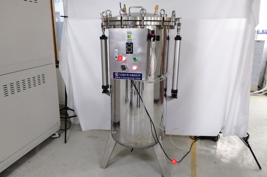
Figure 4
4. Pre-test Preparations
4.1 Open the cover plate
There is a pry bar here, which is used to loosen or tighten the screws on the cover plate latches.
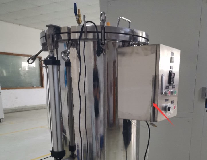
Figure 5
| No. | Note |
| ① Exhaust Valve | Open the exhaust valve. Note: The valve is open when the handle is parallel to the pipe and closed when it is perpendicular to the pipe. |
| ② Safety Valve | No action is required |
| ③ Buckle | Use a pry bar to unscrew all the latches and remove them. |
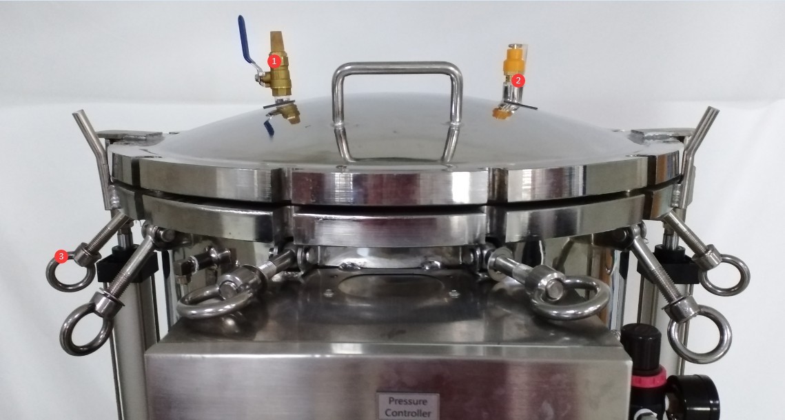
Figure 6
This is a three-position switch for controlling the water tank cover: On/Pause/Off. Turn it to the “On” position to use the air compressor to open the water tank cover. Once the cover has reached its highest position, turn the switch to “Pause.”
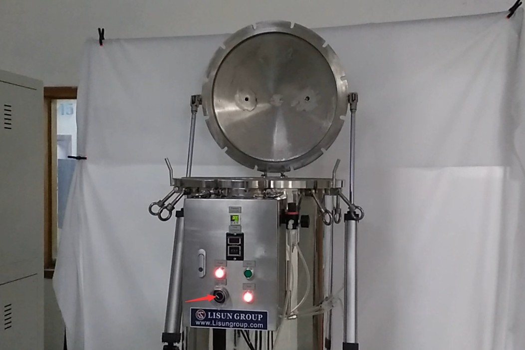
Figure 7
4.2 Water for Testing
Refer to Section 3.2 for instructions on using the water inlet. Alternatively, refer to Section 4.1: open the cover and pour the test water directly into the water tank. The side of the water tank features a transparent hose and a scale, allowing you to check the water level.
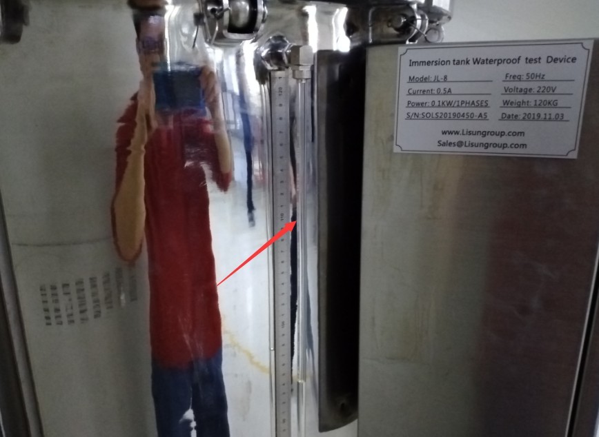
Figure 8
Please note that this is the air compressor’s intake port; the water level in the tank must be below this intake port.
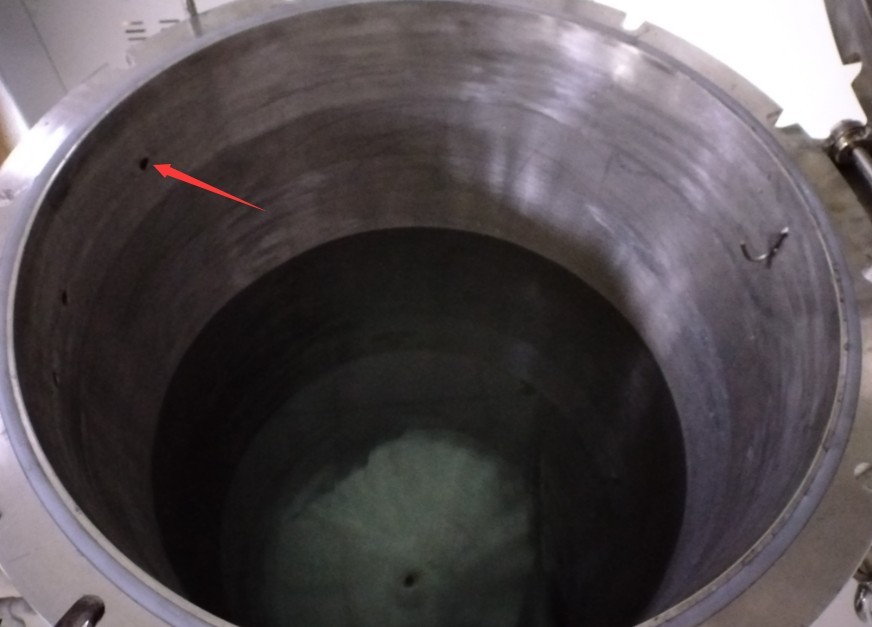
Figure 9
Note: Take into account changes in the water level after samples of different volumes are placed in the water tank.
4.3 Preparation of Test Samples
4.3.1 Visual Inspection of Samples
Inspect the test samples to ensure there are no visible cracks or deformations, and that there are no cracks or peeling at the product interfaces or seals;
The sample surface must be free of oil or water stains to prevent contamination of the test water.
4.3.2 Preparation of Sample Holders
Suspend the sample from a hook inside the water tank using straps, ropes, or similar fasteners, ensuring the sample is submerged in the water. Depending on the specific circumstances, you may place auxiliary supports inside the tank to ensure the sample is securely suspended from the mounting points within the tank, preventing it from swaying, falling, or scratching the inner walls of the tank during the test.
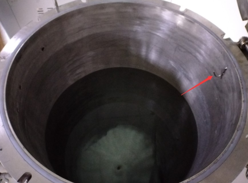
Figure 10
4.3.3 Measures to Prevent Samples from Floating
If the sample floats and cannot be fully submerged, add a weight; secure the weight to the bottom of the sample with a strap to prevent damage to the sample; after adding the weight, ensure that the sample is fully submerged and securely suspended.
4.4 Close the cover
Set the three-position switch that controls the cover to “Off.” Once the cover is completely closed, switch it back to “Stop.”
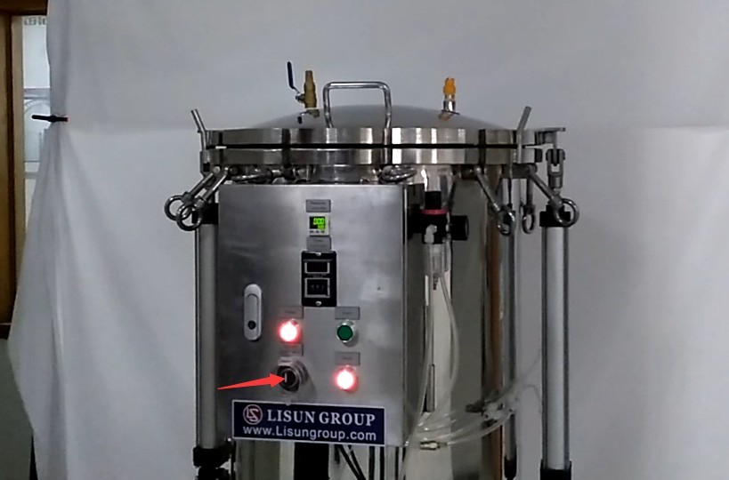
Figure 11
| No. | Note |
| ① Snap fastener | Secure the water tank cover with all the latches and reinforce it with a pry bar. |
| ② Air Vent | Close the exhaust valve |
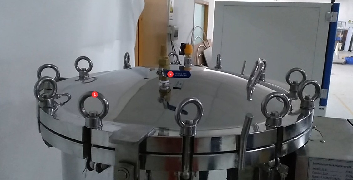
Figure 12
5. Water Immersion Test
5.1 Setting the Test Pressure Value
5.1.1 Water Depth and Pressure Values
There is a linear relationship between the test water depth and the pressure value. The pressure value can be set using the pressure controller; refer to the reference table.
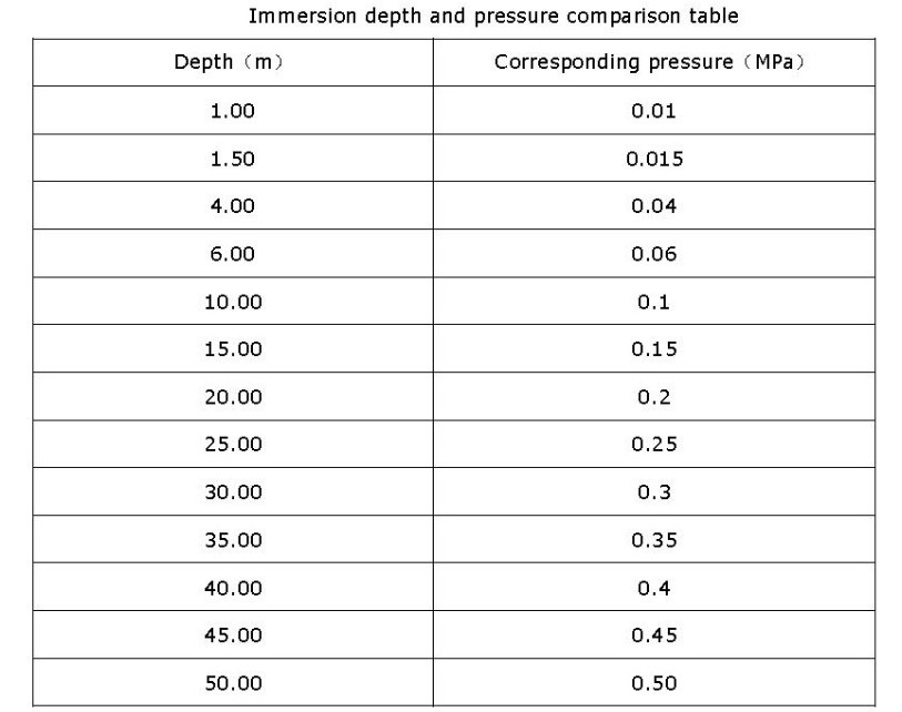
Figure 13
Note: The general standards do not specify the required water depth for testing; users must determine the test water depth themselves based on the requirements for the respective samples.
5.1.2 Pressure Controller Operation
| No. | Note |
| ① Settings button | After pressing the button, select the parameter you want to configure. |
| ② Up Arrow Key | Increase the value |
| ③ Down Arrow Key | Set the value to a lower number |
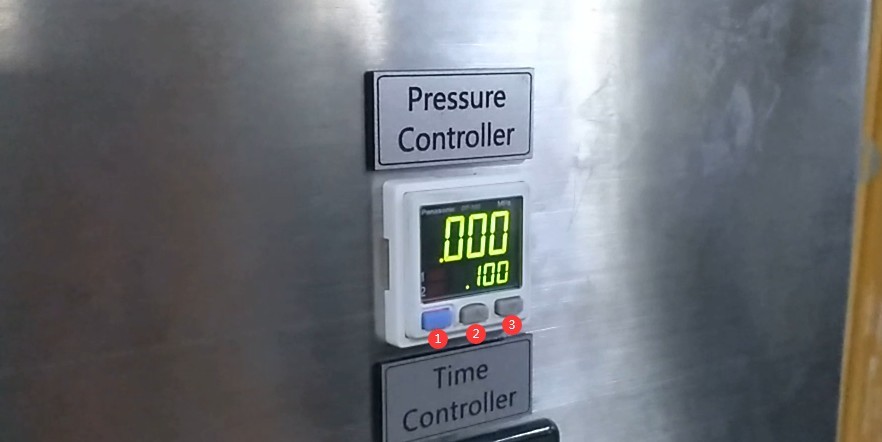
Figure 14
The pressure controller can be set with an upper limit (Hi), a lower limit (Lo), and an error value (P). The relationship among these three values is fixed: P value: Factory-set to 0.002 MPa; no adjustment is required. This value represents the difference between the upper and lower pressure limits; Lo = Hi – 0.002 MPa: This ensures that the device automatically compensates for pressure fluctuations to maintain stable pressure.
For example: When testing a water depth of 10 meters, if Hi = 0.100 MPa, then Lo = 0.098 MPa and P = 0.002 MPa.
Press the Set button. The “P” value does not need to be changed; 0.002 represents the difference between the upper and lower pressure limits. Press the Set button again, and use the up and down adjustment buttons to set the “Lo” lower pressure limit to 0.098. Press the Set button once more, and set the “Hi” upper pressure limit to 0.1. The setup is complete.
5.2 Setting the Test Duration
The general standards do not specify a test duration; users must determine the test duration themselves based on the requirements for the specific sample.
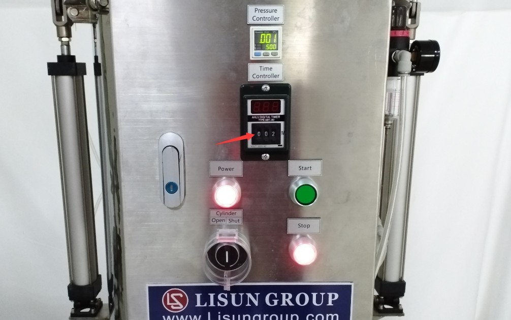
Figure 15
5.3 Test Procedure
5.3.1 Start-up Test
| No. | Note |
| ① | Press the green start button, and the air compressor begins compressing air into the water tank. |
| ② | The value displayed here is the current pressure, which is rising slowly. |
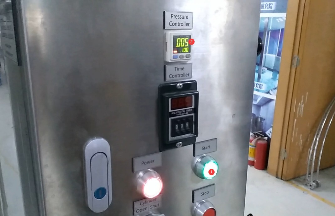
Figure 16
5.3.2 Test Timing
| No. | Note |
| ① | When the current pressure reaches the set “Hi” upper pressure limit, the air compressor stops feeding gas into the tank. |
| ② | The timer turns on automatically and starts counting down; the test officially begins. |
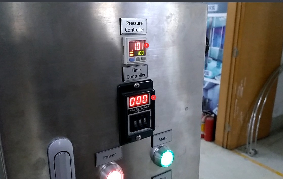
Figure 17
Note: Air will gradually escape from the tank. When the pressure drops below the set “Lo” lower limit, the system will automatically replenish compressed air into the tank until the pressure reaches the set “Hi” upper limit again.
5.3.3 End of the Test
When you press the Stop button, or when the test duration reaches the set time:
| No. | Note |
| ① | The Stop button lights up |
| ② | The power button is off |
| ③ | Timer Off |
| ④ | The tank begins to automatically relieve pressure until the pressure inside the tank returns to 0. |
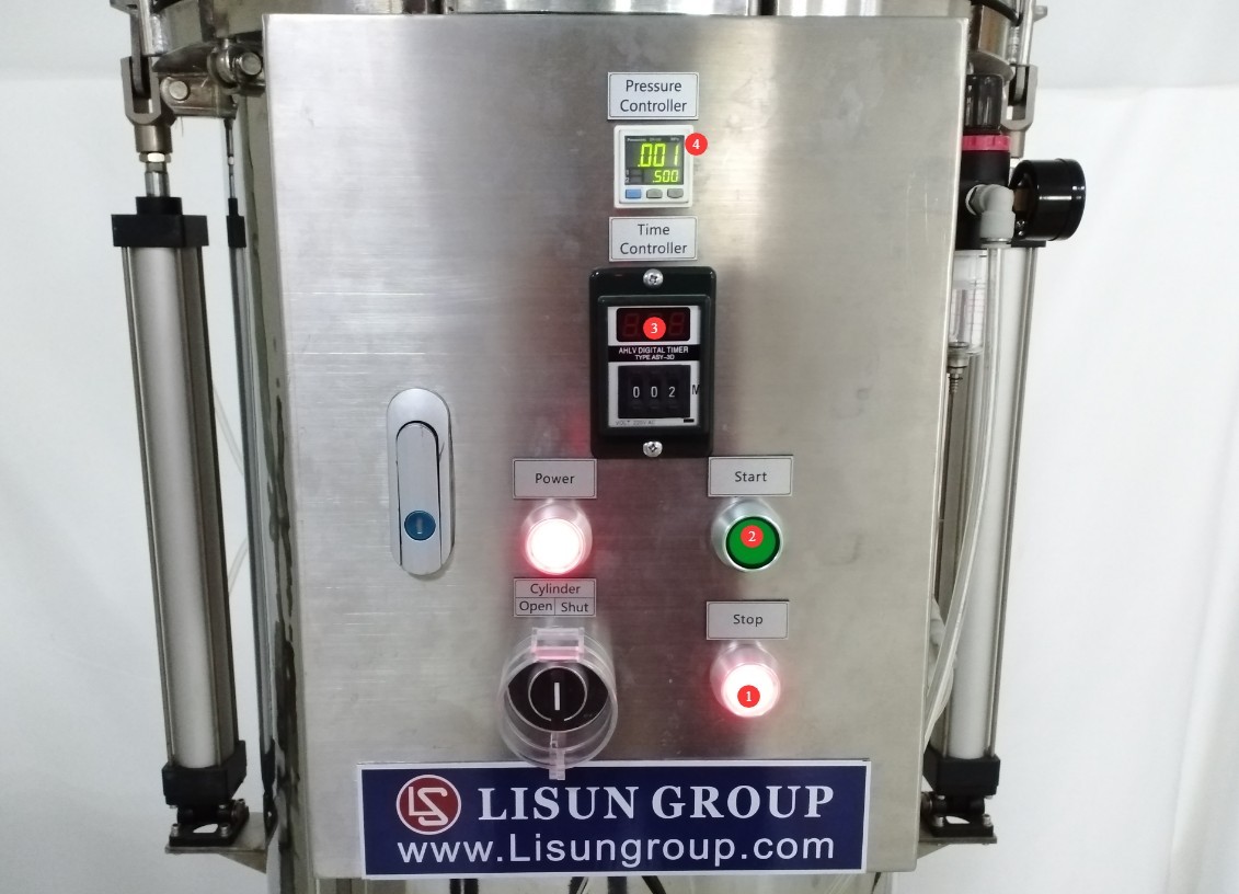
Figure 18
6. Post-Test Procedures
6.1 Immediate Actions Upon Test Completion
6.1.1 Water Tank Pressure Relief
As noted in Section 5.3.3, the tank will automatically depressurize after the test is complete. You may open the vent valve to depressurize the tank quickly.
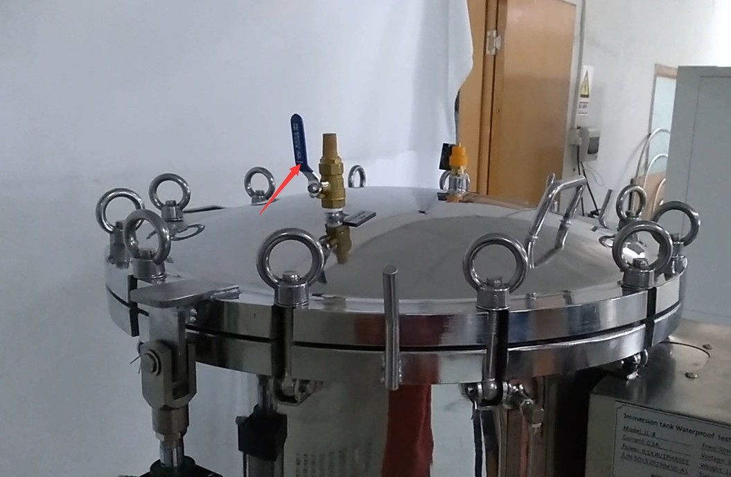
Figure 19
6.1.2 Remove the sample
Be sure to wait until the tank has fully depressurized and the vent valve is open before opening the cover plate (see Section 4.1). Remove the sample.
6.2 Shutdown
After all tests for the day are completed, turn off the equipment’s power switch, shut down the air compressor, or disconnect the air intake hose.
6.3 Evaluation of Test Results
Use a dry cloth to wipe away any water stains from the outer surface of the sample, and then test the sample. Determine whether the sample has passed the test based on the following criteria.
| Evaluation Criteria | Specific Requirements |
| Appearance | No deformation, no damage, no signs of water damage |
| Safety | Insufficient water supply does not affect the normal operation of the equipment or compromise safety. |
| Insulation Protection | Water does not accumulate on insulated components where it could cause tracking along the creepage distance. |
| Protection of Electrical Components | Water must not enter live parts or windings that are not designed to operate in damp conditions. |
| Cable Protection | Water does not accumulate near the cable terminations or enter the cable |
| Effectiveness of Drainage Holes | If there are drain holes, it must be demonstrated that incoming water will not accumulate and that it can be drained without damaging the equipment. |
| Equipment without a drain hole | If water accumulates and poses a threat to live parts, follow the acceptance criteria specified in the relevant product standards. |
7. Daily Maintenance and Care of Equipment
7.1 Daily Cleaning
Inspect the appearance of the test water in the tank. If it is clear, free of cloudiness, impurities, and oil, the water quality is good and it can continue to be used. If the water is cloudy, contains impurities, or has oil in it, immediately replace all the water in the tank, clean the interior walls of the tank, and then refill it with water;
Wipe water spots and dust from the surface of the equipment to prevent water spots from forming limescale;
Wipe down the control cabinet area with a dry cloth to prevent water and dust from entering the internal circuitry.
7.2 Regular Inspections
Connections: Check all water, electrical, and air connections to ensure there are no water leaks, loose connections, or air leaks;
Water tank cover gasket: No signs of aging, cracking, or deformation; the sealing surface must be free of scratches or dents. Replace immediately if damaged;
Thoroughly clean the water tank at least once a week: Drain any standing water, then wipe it dry with a dry cloth. After cleaning, check the interior walls of the tank for rust or scale. If there is minor rust, gently wipe it with a rust remover, then rinse thoroughly with clean water.
7.3 Maintenance of Idle Equipment
7.3.1 Short-term idling (within 1 month)
Drain all water from the tank and the water lines, and wipe them dry with a cloth to prevent scale buildup inside the tank and in the pipes;
Disconnect the intake hose;
Cover the entire unit with a dust-proof cloth to prevent dust from getting inside;
Keep the equipment in a dry, well-ventilated area.
7.3.2 Long-term inactivity (more than 1 month)
Complete all maintenance tasks for short-term storage; disconnect all electrical and water connections from the equipment; remove the water hoses, let them air dry, and store them properly;
Apply a layer of rust-preventive oil to the inner walls of the water tank and the surfaces of metal parts to prevent rust; store the equipment in a cool, dry place away from direct sunlight;
The equipment should be powered on once a month and left running for 5 to 10 minutes before being turned off to prevent circuit deterioration.
8. Troubleshooting and Resolving Common Problems
| Fault Symptoms | Possible Causes | Procedure |
| The timer isn’t displaying | The trial has not officially begun. | The test will not officially begin until the air pressure inside the tank reaches the set value, at which point the timer will appear on the display and start counting down. |
| The pressure cannot rise to the set value | The cover plate is not securely fastened, the exhaust valve is not closed, the inlet and outlet valves are not closed, and the inlet pressure is insufficient. | Verify that the gasket between the cover plate and the water tank is in good condition and there are no air leaks, then use a pry bar to secure all latches; close the exhaust valve; close the inlet and outlet valves; check the pressure at the intake valve and adjust it to 0.8 MPa; if you cannot increase the pressure, check the air compressor and the intake hose connections. |