
 English
 中文简体
中文简体 English
 Русский
 Español
 Português
 Türkçe
 العربية
 Deutsch
 Polski
 Italiano
 Français
 한국어
한국어 ไทย
ไทย Tiếng Việt
 日本語
日本語





























Attenuator For Goniophotometer
User's Manual
Applicable LISUN models: LSG-1800A、LSG-1800ACCD、LSG-1890B、LSG-1890BCCD
1. Product Overview
1.1 Use Cases
This attenuator is a dedicated accessory for the LSG series of Goniophotomoeters. It is used to reduce excessively strong light signals, bringing them within the probe’s normal measurement range, thereby ensuring that testing can proceed normally for high-power luminaires with narrow beam angles or in scenarios with short test distances.
During a normal test, the software displays the following prompt (Figure 1-1), indicating that an attenuator must be used when a signal overflows; otherwise, the test cannot be completed.
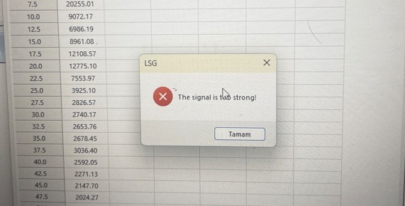
Figure 1-1
1.2 Key Features
Neutral optical attenuation reduces only the light intensity without altering other parameters of the light signal; the product is factory-calibrated to ensure precise attenuation coefficients; it can be used individually or in combination with multiple units; compatible with LSG series Goniophotomoeter probes for easy installation.
2. Product Introduction
2.1 Introduction to Attenuators
See Figure 2-1.
| Number | Note |
| ① | Attenuator Serial Number |
| ② | Attenuation Coefficient of an Attenuator |
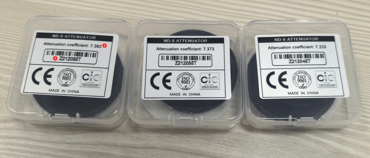
Figure 2-1
Note: Each attenuator has a unique serial number and attenuation coefficient; please take this into account when using them.
2.2 Rules of Use
When used individually, the attenuation coefficient can be applied directly; when used in combination, the total attenuation coefficient equals the product of the individual coefficients. Example: Z212055T × Z212045T = 7.373 × 7.223 = 53.255179
Note: The software only accepts three decimal places; the fourth decimal place is rounded. For example, if the coefficient is 53.255179, enter 53.255.
2.3 Principles of Use
Do not use attenuators unless necessary: Do not install them when the signal is normal to avoid unnecessary attenuation; do not use multiple attenuators unless necessary: Use a single attenuator whenever possible to minimize cumulative error.
3. Installation and Use
3.1 Installation of Attenuators
Remove the light shield from the front of the probe, rotate the attenuator clockwise to attach it to the probe connector, and ensure it is securely fastened, as shown in Figures 3-1 and 3-2.
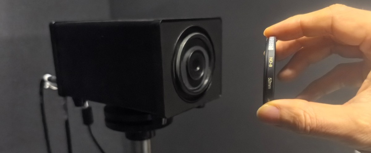
Figure 3-1
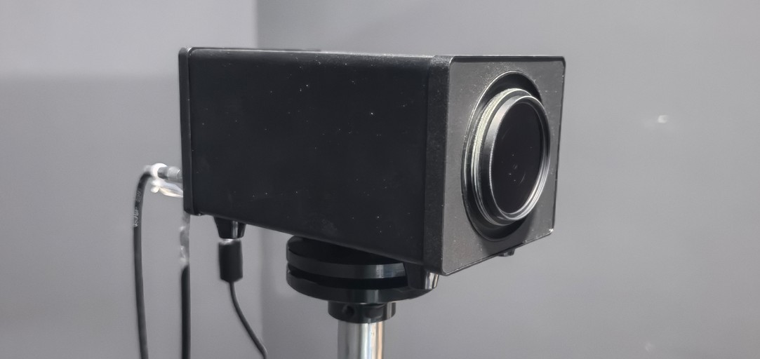
Figure 3-2
If you need to install multiple attenuators, stack the second and subsequent attenuators clockwise in the same manner. Once all attenuators are installed, reattach the light shield, as shown in Figure 3-3.
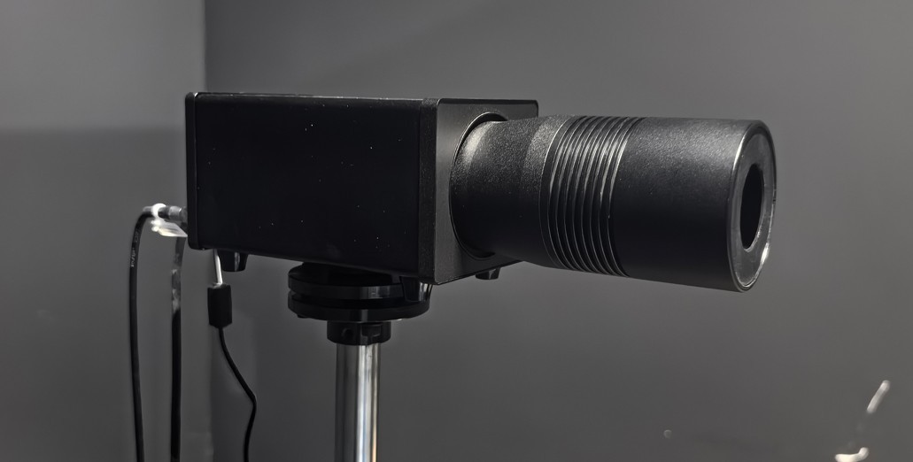
Figure 3-3
3.2 Setting the Attenuation Coefficient
Press the PM400C device settings button, as shown in Figure 3-4.
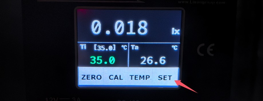
Figure 3-4
Click “Next Page” on the screen, as shown in Figure 3-5.
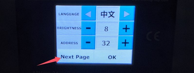
Figure 3-5
Refer to Figure 3-6 and locate the “Filter Coefficient” option. When no attenuator is used, the default coefficient is 1.000. When an attenuator is used, enter the corresponding precise coefficient. Each time you add or remove an attenuator, you must promptly adjust the attenuation coefficient.
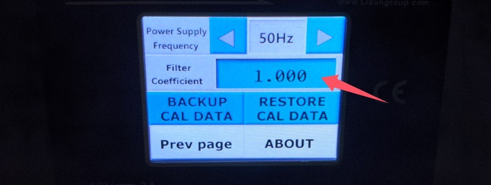
Figure 3-6
3.3 Testing
Refer to the Goniophotomoeter user manual and perform the test as usual.
4. Routine Maintenance and Care
4.1 Cleaning Optical Surfaces
Gently wipe the optical surface only with lens paper or a lint-free cloth; do not touch it with paper towels or your fingers. If there are stains, dip a small amount of anhydrous alcohol and wipe gently; do not scratch or bump the optical surface.
4.2 Storage and Handling
When not in use, store it in its original protective case in a dry, dust-free environment; avoid high temperatures, humidity, and corrosive gases; it is recommended to include a desiccant; protect it from being crushed or dropped to prevent damage to the optical surface.
4.3 Routine Inspections
Before use, inspect the optical surface for scratches, cracks, or mold; if any are found, stop using it immediately and replace it with a new attenuator.
4.4 Calibration Interval Requirements
To ensure the measurement accuracy and operational reliability of the equipment, it is recommended that it be sent periodically to a qualified third-party metrology organization for calibration. The recommended calibration interval is 12 months. Users may determine the specific calibration interval based on frequency of use, environmental conditions, and quality system requirements.
5. Troubleshooting and Resolution
| Fault Symptoms | Possible Causes | Procedure |
| A “signal overflow” error still appears after installing the attenuator. | PM400C Coefficient Error, Insufficient Attenuation Coefficient | Refer to Section 3.2 to confirm that the coefficient has been corrected; install an attenuation plate to increase the attenuation coefficient. |
| The test data showed significant deviations after using the attenuator. | PM400C Coefficient Error, Excessive Use of Attenuators, Damaged Attenuators | Refer to Section 3.2 to verify that the attenuation coefficient has been corrected; reduce the number of attenuators to lower the attenuation coefficient while ensuring there is no signal overflow; check the attenuators for dirt or damage, and replace them if necessary. |