
 English
 中文简体
中文简体 English
 Русский
 Español
 Português
 Türkçe
 العربية
 Deutsch
 Polski
 Italiano
 Français
 한국어
한국어 ไทย
ไทย Tiếng Việt
 日本語
日本語





























Test Probe Kits Of IEC 60335-1
User's Manual
Applicable LISUN models: SMT-1211、SMT-1213、SMT-1241、SMT-335F7、SMT-5753、SMT-635K、SMT-PBC
1. Basic Understanding of Test Fixtures
1.1 Applicable Standards
The SMT-635K Test Probe Kits of IEC 60335-1 are standardized sets of test tools designed specifically for safety testing of household and similar electrical appliances. All test fixtures are manufactured in strict accordance with the relevant clauses of GB/T 4706.1-2024 (IEC 60335-1).
Used to verify core safety performance characteristics of electrical products, such as protection against accidental contact, mechanical strength, structural reliability, and insulation and heat resistance; suitable for quality inspection departments at electrical appliance manufacturers, third-party testing laboratories, certification bodies, and other similar settings.
1.2 Scope of Application and Test Principles
1.2.1 Scope of Applicable Products
This test kit is suitable for safety testing of household and similar electrical appliances with a rated voltage not exceeding 250 V. It covers categories such as small appliances, lighting fixtures, power tools, and kitchen appliances, and can also be used to verify the protective performance of enclosures for other electrical products that meet the corresponding protection rating requirements.
1.2.2 Core Test Principles
By simulating various contact and by simulating various contact and pressure scenarios—such as human fingers, metal pins, thin probes, fingernails, and rigid pressure-applying tips—and applying the force values specified in the standard to openings in electrical enclosures, insulated surfaces, and protective components, this test verifies whether live parts and hazardous moving parts are accessible and whether protective structures and insulating materials meet safety requirements, thereby determining whether the product complies with the standard’s safety provisions.
1.3 Test Specimen Composition and Correspondence to Standards
| Test Fixture Name | Corresponding Standard Provisions |
| Hinge Test Finger (Test Specimen B) | GB/T 4706.1-2024 (IEC 60335-1), Clause 8.1.1 |
| Test Pin (Test Fixture 13) | GB/T 4706.1-2024 (IEC 60335-1), Clause 8.1.2 |
| Test Probe (Test Fixture 41) | GB/T 4706.1-2024 (IEC 60335-1), Section 8.1.3 |
| Modified Test Fixture B (Round Stop Plate) | GB/T 4706.1-2024 (IEC 60335-1), Clause 20.2 |
| Test Nails | GB/T 4706.1-2024 (IEC 60335-1), Clause 21.2 |
| Thrust Test Finger (Test Fixture 11) | GB/T 4706.1-2024 (IEC 60335-1), Clause 22.11 |
1.4 Downloading Electronic Documents
We have already sent the download links for the electronic user manual, calibration certificate, warranty card, and other documents via email at the time of shipment. Please download them as soon as possible. If you have not received the email, please contact us to request the download links again.
2. Safety Precautions
2.1 Test Environment Requirements
2.1.1 Environmental Conditions
Tests should be conducted under normal temperature and humidity conditions, with an ambient temperature of 15°C to 35°C and a relative humidity of 25% to 75%. Live-line testing is prohibited in environments containing flammable or explosive gases to prevent safety incidents.
2.1.2 Workbench Requirements
The device under test should be placed on a sturdy, level, insulated work surface and must not be moved during the test; sufficient operating space must be provided around the work surface to prevent contact with other live equipment during the test.
2.2 Operational Safety Guidelines
2.2.1 Safety in the Operation of Machinery
Apply force slowly and evenly; do not apply force suddenly or pry on the equipment housing, to avoid damaging the test fixture or causing injury from bumps or impacts.
When testing equipment with sharp edges, wear protective gloves to prevent cuts from burrs on the equipment housing.
Test fixtures are precision measuring instruments; do not strike, throw, or use them as prying tools.
During the test, do not point the test fixture at any part of the body to prevent mechanical injury while applying force.
2.2.2 Electrical Safety of the Equipment Under Test
Unless otherwise specified by special live-line testing requirements, prior to routine protection against accidental contact testing, the equipment under test must be disconnected from the main power source, and any energy-storing components, such as internal capacitors, must be fully discharged.
The test circuit must supply power to the live components under test only through the provided test power supply; connecting the equipment under test to the mains for testing is prohibited.
2.3 Safety Precautions for Test Fixtures
Do not perform tests using forces that exceed the values specified in the standard, to avoid damaging the equipment under test or causing permanent deformation of the test fixtures.
Do not allow the device to come into contact with corrosive substances such as strong acids and strong alkalis, to prevent corrosion of metal parts and deterioration of the insulated handle.
3. Introduction to Test Fixtures
3.1 Standard Diagram
3.1.1 Hinge Test Finger (Test Fixture B)
See Figure 3-1 (taken from IEC 61032, Figure 2).
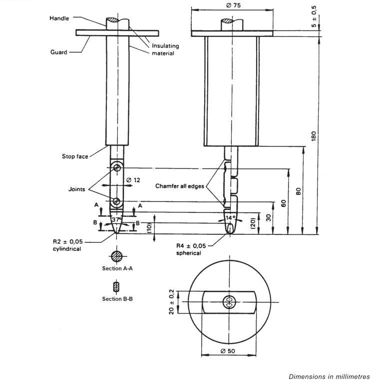
Figure 3-1
3.1.2 Test Pin (Test Fixture 13)
See Figure 3-2 (taken from IEC 61032, Figure 9).
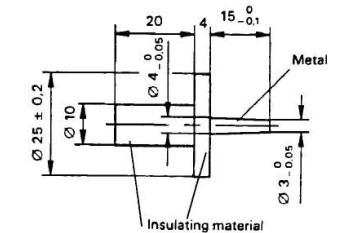
Figure 3-2
3.1.3 Test Probe (Test Fixture 41)
See Figure 3-3 (taken from IEC 61032, Figure 16).
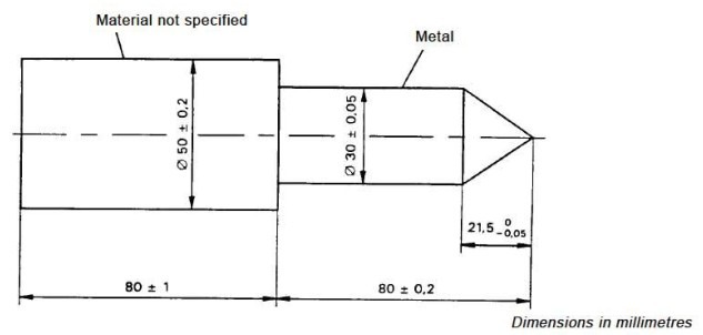
Figure 3-3
3.1.4 Modified Test Fixture B
Structural Composition: The thrust transmission structure has been optimized based on the design of Test Specimen B. This test specimen features a circular stop plate with a diameter of 50 mm, which replaces the original non-circular stop plate. The dimensions and articulation of the finger are identical to those of Test Specimen B.
3.1.5 Test Nails
See Figures 3–4 (taken from IEC 60335, Figure 7).
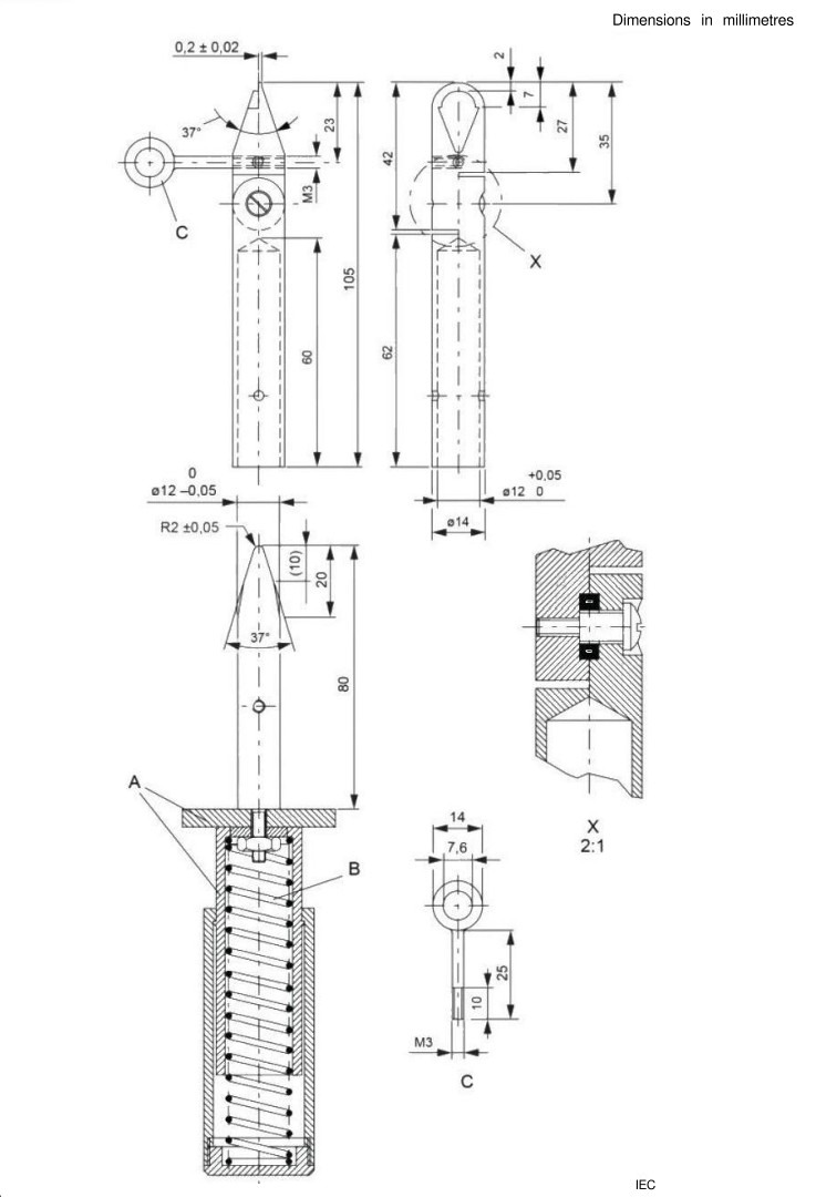
Figure 3-4
3.1.6 Thrust Test Finger (Test Fixture 11)
See Figures 3–5 (taken from IEC 60335, Figure 7).
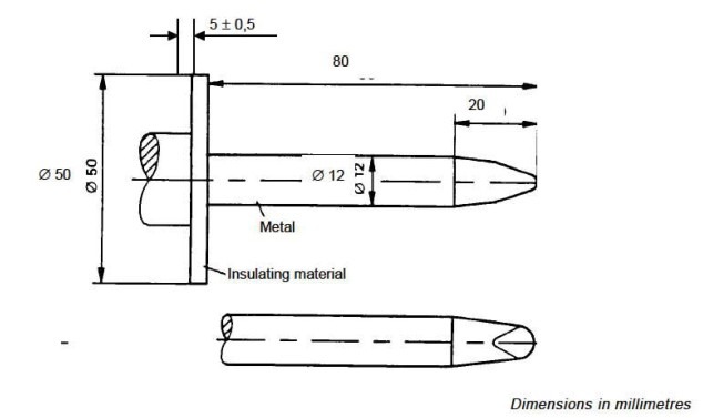
Figure 3-5
3.2 Photographs of the Actual Object
See Figures 3–6.
| LISUN Model | Note |
| ① SMT-PB | Hinge Test Finger (Test Specimen B) |
| ② SMT-1213 | Test Pin (Test Fixture 13) |
| ③ SMT-1241 | Test Probe (Test Fixture 41) |
| ④ SMT-PBC | Modified Test Fixture B (Round Stop Plate) |
| ⑤ SMT-335F7 | Test Finger, comes with a 50N force gauge |
| ⑥ SMT-1211 | Thrust Test Finger (Test Fixture 11) |
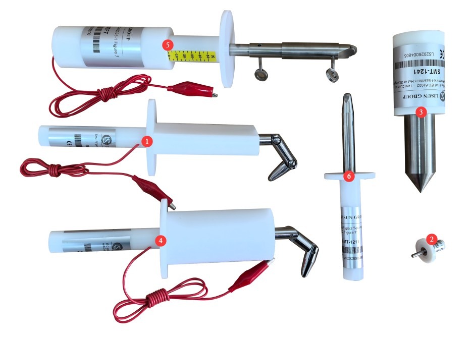
Figure 3-6
3.3 Test Fixture Auxiliary Functions
3.3.1 With or without wires
When LLISUN series test fixtures are shipped, some models come standard with conductive test leads, while others are configured without leads.
To determine whether the live parts of the device under test are accessible, use the version with wires; if you are only verifying whether mechanical openings can be breached or whether hazardous mechanical parts are accessible, the version with wires is not required.
Before purchasing, users can specify whether they want this test fixture to include or exclude a cable based on their actual needs.
3.3.2 Does it come with a thrust meter?
Some LISUN test fixtures come with a thrust gauge as standard, while others do not.
If the user already has a thrust gauge that meets the specifications, they may choose the model without a built-in thrust gauge. You may specify whether you want a built-in thrust gauge based on your actual needs. Note: The price may vary depending on whether the thrust gauge is included.
4. Test Specimen Testing Procedures
4.1 Preparation of the Device Under Test
4.1.1 Status Confirmation
Verify that the enclosure of the device under test is intact and undamaged; all removable covers, knobs, fuse covers, and other components on the device must be properly installed in their normal operating positions; Disconnect all external power sources from the device under test and unplug the power cord; discharge any high-capacity capacitors and energy storage components inside the device to ensure there is no residual voltage; for devices with rechargeable batteries, remove the batteries or disconnect them.
4.1.2 Sample Pretreatment Requirements
The sample shall be left in the test environment for at least 2 hours to allow its temperature to reach equilibrium with the ambient temperature; for tests involving temperature rise, the test shall be conducted immediately after the temperature rise test.
4.1.3 Installation and Mounting
Place or secure the equipment under test on the test bench in its normal operating condition, with all removable parts of the enclosure properly installed and fasteners tightened to their normal operating condition; if installation methods such as wall mounting or suspension need to be simulated, secure the specimen according to its actual operating conditions; Ensure that the sample does not shift or tip over due to the application of test forces during the test.
4.2 Preparation of Auxiliary Equipment
4.2.1 Push-Pull Gauge
Used to precisely control the force applied during testing.
4.2.2 Safety Extra-Low-Voltage Power Supply
When used with a test fixture, this device triggers an audible and visual alarm upon contact with live parts. The LISUN SMT-529CV can be used to provide a test voltage of 40–45 V to simulate contact with fingers, tools, and metal wires; it is compatible with all types of test fixtures with wires. See Figure 4-1.
| Number | Note |
| ① | Test Voltage Display |
| ② | Test voltage output, used to connect the test leads at the rear of the test fixture |
| ③ | Test voltage circuit; cable used to connect the device under test |
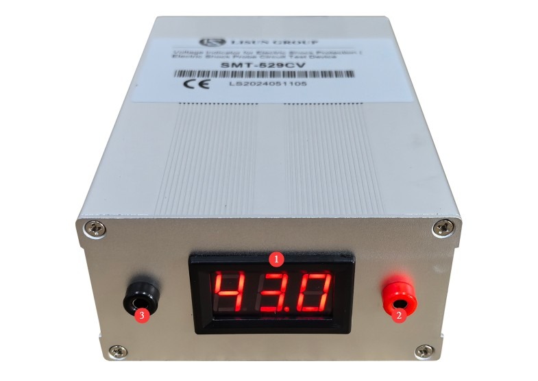
Figure 4-1
4.3 Operation and Evaluation
For specific test procedures, please refer to the relevant sections of the standard for detailed requirements regarding operation and evaluation.
5. Routine Maintenance and Care of Test Fixtures
5.1 Daily Cleaning and Maintenance
Wipe away any dust or grease from the surface of the Test Finger using a clean, soft cloth.
Gently wipe the metal parts with anhydrous ethanol to remove stains and fingerprints.
Wipe the insulated handle with a mild detergent and dry it thoroughly. Do not use strong solvents to clean it.
Use a soft-bristled brush to remove dust from the joint gaps, and apply a small amount of neutral lubricating grease to keep the parts moving smoothly.
5.2 Long-Term Storage and Maintenance
After completing routine cleaning and maintenance, apply a thin layer of rust-preventive oil to the metal surface, wrap it in rust-preventive paper, place a dust cover over it, and store it in a dry, well-ventilated warehouse.
The test fixtures must be stored in their designated storage box to avoid crushing or impact and prevent deformation.
5.3 Calibration Interval Requirements
To ensure the measurement accuracy and operational reliability of the test equipment, it is recommended that it be sent periodically to a qualified third-party metrology laboratory for calibration. The recommended calibration interval is 12 months. Users may determine the specific calibration interval based on usage frequency, environmental conditions, and quality system requirements.
6. Troubleshooting and Resolving Common Problems
| Fault Symptoms | Possible Causes | Procedure |
| Joint Stiffness | Dust enters the joint space | Clean the joint gaps with anhydrous ethanol, let them air dry, and then apply a neutral lubricating grease. |
| Poor electrical conductivity; abnormal results in the electric shock protection test | Aged or loose cables | Use a multimeter to measure the resistance between the Test Finger of the test probe and the terminal at the end of the cable. If the resistance is greater than 1 Ω, it will affect the test results; in this case, check the wiring or return the unit to the factory for repair. |