
 English
 中文简体
中文简体 English
 Русский
 Español
 Português
 Türkçe
 العربية
 Deutsch
 Polski
 Italiano
 Français
 한국어
한국어 ไทย
ไทย Tiếng Việt
 日本語
日本語





























Test Probe Kits Of IEC 60529
User's Manual
Applicable LISUN models: SMT-02T10、SMT-529CV、SMT-529T、SMT-A50、SMT-IP30T、SMT-IP40T
1. Basic Understanding of Test Fixtures
1.1 Applicable Standards
The SMT-529T Test Probe Kits of IEC 60529 are specialized testing fixtures designed and manufactured in accordance with GB/T 4208-2017 “Degrees of Protection Provided by Enclosures (IP Code)” (equivalent to IEC 60529:2013).
Used to verify the ability of electrical equipment enclosures to protect personnel from contact with internal hazardous live parts and hazardous moving parts, corresponding to protection levels 1 through 4 as indicated by the first characteristic digit in the IP code. The kit integrates all four types of contact test fixtures specified by the standard, along with the corresponding safety extra-low-voltage indicator devices, and can be widely used for IP protection rating testing and quality verification of products such as electronic and electrical appliances, lighting equipment, and low-voltage electrical devices.
1.2 Applicable Test Levels
This kit can verify protection levels where the first digit of the IP code is 1, 2, 3, or 4. The corresponding protection levels are as follows:
IP1X: Protects the back of the hand from coming into contact with hazardous components inside the enclosure;
IP2X: Prevents human fingers from coming into contact with hazardous parts inside the enclosure;
IP3X: Prevents tools with a diameter of 2.5 mm (such as screwdrivers) from penetrating and coming into contact with hazardous parts;
IP4X: Prevents a metal wire with a diameter of 1.0 mm from penetrating and coming into contact with hazardous parts.
1.3 Explanation of the Test Principle
By simulating the size and shape of human body parts or foreign objects, a specified force is applied to all openings and gaps in the enclosure of the device under test.
The accompanying test power supply (safety extra-low voltage power supply) complies with the requirements of Clause 12.2 of GB/T 4208-2017 (IEC 60529:2013) and forms a closed circuit in series with the safety extra-low voltage power supply, the test fixture, and the live parts of the equipment under test. When the test probe comes into contact with a hazardous live part inside the device under test, the circuit is completed, the power supply triggers an alarm, and it is immediately evident that the test probe has made contact with a hazardous part.
1.4 Downloading Electronic Documents
We have already sent download links for the electronic user manual, calibration certificate, warranty card, and other documents via email at the time of shipment. Please download them promptly. If you have not received the email, please contact us to request the download links again.
2. Safety Precautions
2.1 Electrical Safety
The test power supply operates at 220 V AC ±10% with a frequency of 50 Hz or 60 Hz. A three-prong outlet with protective grounding must be used, and the protective grounding resistance must be ≤4 Ω. Disconnecting or removing the protective grounding wire is strictly prohibited, as doing so poses a risk of electric shock.
2.2 Test Environment Requirements
2.2.1 Environmental Conditions
Tests should be conducted under normal temperature and humidity conditions, with an ambient temperature of 15°C to 35°C and a relative humidity of 25% to 75%. Live-line testing is strictly prohibited in environments containing flammable or explosive gases to prevent safety incidents.
2.2.2 Workbench Requirements
The device under test should be placed on a sturdy, level, insulated work surface and must not be moved during the test; sufficient operating space must be left around the work surface to prevent contact with other live equipment during the test.
2.3 Operational Safety Guidelines
2.3.1 Safety in the Operation of Machinery
Apply force slowly and evenly; do not apply sudden force or pry on the equipment housing, to avoid damaging the test fixture or causing injuries from collisions.
When testing equipment with sharp edges, wear protective gloves to prevent cuts from burrs on the equipment housing.
Test fixtures are precision measuring instruments; do not strike, throw, or use them as prying tools.
During the test, it is strictly prohibited to point the test fixture at any part of the human body to prevent mechanical injury while applying force.
2.3.2 Electrical Safety of the Device Under Test
Unless otherwise specified in special live-line testing requirements, prior to routine protection against accidental contact testing, the equipment under test must be disconnected from the main power supply, and any energy-storing components, such as internal capacitors, must be fully discharged.
The test circuit must supply power to the live components under test only through the provided test power supply; connecting the equipment under test to the mains power supply for testing is strictly prohibited.
2.4 Safety Precautions for Test Fixtures
Do not perform tests using forces that exceed the specified limits to avoid damaging the equipment under test or causing permanent deformation of the test fixture.
Do not allow the tool to come into contact with corrosive substances such as strong acids and strong alkalis, to prevent corrosion of metal parts and deterioration of the insulated handle.
3. Introduction to the Contact Test Fixture
3.1 Standard Diagram
See Figure 3-1 (taken from IEC 60529:2013, Table 6).
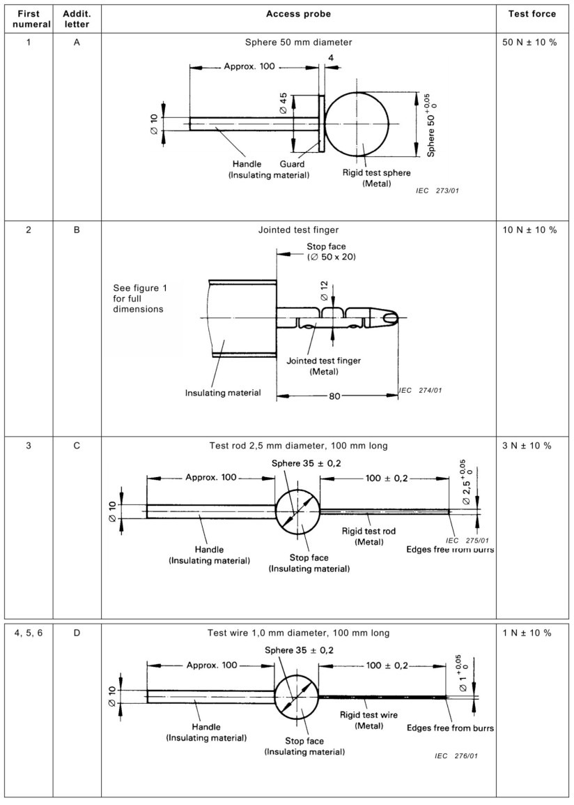
Figure 3-1
3.2 Photographs of the Actual Object
See Figure 3-2.
| Test Power Supply (Safety Extra-Low Voltage Power Supply) | |
| ① | Test Voltage Display |
| ② | Test voltage output, used for the test leads connected to the rear end of the test fixture |
| ③ | Test voltage circuit; cable used to connect the device under test |
| ④ | Connection Cable |
| Contact with the test specimen | |
| ⑤ | IP3X Rigid Test Probe, equipped with a 3N force gauge, corresponding to the first characteristic digit “3” in Table 6 of IEC 60529:2013 |
| ⑥ | The IP2X hinging test refers to a test using a 10-N force gauge, corresponding to the first characteristic digit 2 in Table 6 of IEC 60529:2013. |
| ⑦ | IP4X Rigid Test Lead with Built-in 1N Force Gauge, corresponding to Characteristic Digit 4 in Table 6 of IEC 60529:2013 |
| ⑧ | IP1X spherical test fixture, equipped with a 50-N force gauge, corresponding to the first characteristic digit 1 in Table 6 of IEC 60529:2013 |
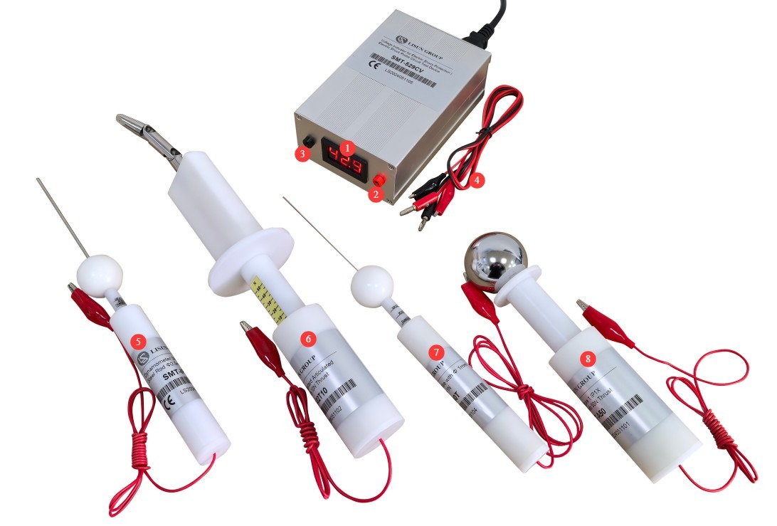
Figure 3-2
4. Preparations Before the Test
4.1 Preparation of the Device Under Test
4.1.1 Status Confirmation
Verify that the enclosure of the device under test is intact and undamaged; all removable covers, knobs, fuse covers, and other components on the device should be properly installed in their normal operating positions; Disconnect all external power sources from the device under test and unplug the power cord; discharge any high-capacity capacitors and energy storage components inside the device to ensure there is no residual voltage; for devices with rechargeable batteries, remove the batteries or disconnect them.
4.1.2 Installation and Mounting
Place or secure the equipment under test on the test bench in its normal operating condition, with all removable parts of the enclosure properly installed and fasteners tightened to their normal operating condition; if installation methods such as wall mounting or suspension need to be simulated, secure the sample according to its actual operating conditions; Ensure that the sample does not shift or tip over during the test due to the application of test forces.
4.2 Test Plan Approval
Determine the nominal IP protection rating of the device under test and identify the required rating for the first digit (1/2/3/4).
Thoroughly inspect the enclosure of the device under test and mark all openings, gaps, assembly clearances, button holes, ventilation holes, wiring holes, and other potential penetration points.
For removable parts (such as covers, doors, and knobs), test points must be marked for each of the three states: installed, removed, and loose.
4.3 Verification of Circuit Connections for Live Components
4.3.1 Verification of Alarm Functions
Turn on the test power supply, short-circuit the test voltage output terminal directly to the test voltage circuit terminal; if the test power supply sounds an alarm, it is functioning normally.
4.3.2 Circuit Connections
Refer to Section 3.2: Connect the output terminal of the test power supply to the cable at the rear of the test fixture to be used, and connect the loop terminal to the cable of the device under test (e.g., if the device under test is AC-powered, connect to the L and N lines of the device’s power cord).
If the equipment under test has multiple independent live circuits, they must be connected separately or tested one after another.
5. Test Procedures for Contact Test Specimens
5.1 General Operating Procedures
5.1.1 Specimen Clamping and Force Application Methods
Hold the test device by its insulated handle; do not touch any metal parts of the device.
Apply the force perpendicular to the plane of the opening being tested, and apply the pressure uniformly along the axis of the test fixture.
Apply the force slowly and smoothly. Monitor the built-in force gauge to ensure that the test force reaches the rated value specified in the standard. Do not apply the force in a sudden, impact-like manner.
At each test point, maintain the rated test force for at least 5 seconds to verify whether any hazardous components have been contacted.
5.1.2 General Specifications for Test Procedures
For each marked test location, the test fixture must be inserted from multiple angles to cover all possible entry directions.
While inserting the test specimen, it may be rotated or swung slightly to simulate the contact positions of the human body or foreign objects during actual use.
Remain focused during the test, verify the alarm status of the test power supply, and ensure that the test fixture has completely passed through the opening in the housing.
Repeat the test 2 to 3 times at the same location to ensure consistent results.
5.2 Specific Procedures for Each Level of Testing
5.2.1 IP1X Spherical Test Fixture Test
Align the sphere with the opening of the housing under test, and slowly apply pressure perpendicular to the opening until the rated test force of 50 N is reached.
Observe whether the sphere passes through the opening: If the sphere cannot fully enter the opening and the test power supply does not trigger an alarm, the IP1X protection rating for that location is deemed合格; if the sphere can fully enter the opening, it is deemed不合格 regardless of whether the test power supply triggers an alarm.
Conduct the test sequentially on all openings, gaps, and the edges of the housing.
5.2.2 IP2X Hinging Test Refers To the test
Align the Test Finger with the opening under test. First, attempt to insert it into the opening while fully extended. As you insert it, adjust the angle of joint flexion according to the shape of the opening to simulate the posture of a finger being inserted. Slowly apply pressure in the direction of insertion until the rated test force of 10 N is reached. While inserting the Test Finger, bend the joints at every possible angle to attempt to touch the internal components, maintaining the rated force for 5 seconds.
Test Results: If the Test Finger cannot pass through the opening, the test is considered passed; if the Test Finger can pass through the opening but the test power supply does not trigger an alarm at any point during the test, this indicates that no hazardous live parts were touched, and the test is considered passed.
Special Note: For narrow, elongated openings such as hinges and gaps, testing must be conducted at multiple points along the length of the opening, and the Test Finger must be inserted at different angles relative to the opening.
5.2.3 IP3X Rigid Test Rod Test
Align the test rod vertically with the opening being tested, slowly apply pressure along the axis, and maintain the rated force of 3 N for 5 seconds. During the test, the test rod may be rotated slightly to attempt insertion from different angles.
Test Results: If the test rod cannot enter the opening, the test is considered passed; if the test rod can enter the opening but the test power supply does not trigger an alarm at any point during the test, the test is considered passed.
For densely spaced openings such as ventilation holes and grilles, tests must be conducted on at least three representative openings.
5.2.4 IP4X Rigid Test Cable Testing
Align the test wire vertically with the opening to be tested, and slowly apply pressure along the axis. Once the rated force of 1 N is reached, hold it for 5 seconds. Do not apply excessive force, as this may cause the wire to bend. During the test, you may slightly adjust the angle to attempt to pass the wire through the gap.
Test Results: If the test cable cannot enter the opening, the test is considered passed; if the test cable can enter the opening but the test power supply does not trigger an alarm at any point during the test, the test is considered passed.
Note: The test line is quite thin, so apply force gently to prevent the line from bending or deforming, which could affect its future use.
6. Routine Maintenance and Care of Test Fixtures
6.1 Daily Cleaning and Maintenance
Wipe away dust and grease from the surface of the test fixture using a clean, soft cloth.
Gently wipe the metal parts with anhydrous ethanol to remove stains and fingerprints.
Wipe the insulated handle with a mild detergent and dry it thoroughly. Do not use strong solvents to clean it.
For the IP2X hinge test, use a soft-bristled brush to remove dust from the gaps between the joints, and apply a small amount of neutral lubricating grease to ensure smooth rotation.
6.2 Long-Term Storage and Maintenance
After completing routine cleaning and maintenance, apply a thin layer of rust-preventive oil to the metal surfaces, wrap them in rust-preventive paper, cover the entire unit with a dust cover, and store it in a dry, well-ventilated warehouse.
The test fixtures must be stored in their designated storage boxes to avoid crushing or impact and prevent deformation.
6.3 Calibration Interval Requirements
To ensure the measurement accuracy and operational reliability of the device, it is recommended that it be sent periodically to a qualified third-party metrology organization for calibration. The recommended calibration interval is 12 months. Users may determine the specific calibration interval based on frequency of use, environmental conditions, and quality system requirements.
7. Troubleshooting and Resolution of Common Problems
| Fault Symptoms | Possible Causes | Procedure |
| IP2X Test Fixture Joint Jamming | Dust enters the joint space | Clean the joint gaps with anhydrous ethanol, let them air dry, and then apply a neutral lubricating grease. |
| Poor electrical conductivity; abnormal results in electric shock protection testing | Aged or loose cables | Use a multimeter to measure the resistance between the Test Finger of the test probe and the terminal at the end of the cable. If the resistance is greater than 1 Ω, it will affect the test results; in this case, check the wiring or return the unit to the factory for repair. |
| The test power supply won’t turn on | Blown fuse | Check the fuse at the power cord connector; if it is blown, replace it with a fuse of the same rating. |
| Deformation and wear of test fixtures | Excessive force, bumps, drops, and wear and tear from long-term use | If a test fixture becomes deformed or worn to the point that its dimensions fall outside the specified tolerances, it must not be used further in accordance with the standard and must be replaced with a new one. |