
 English
 中文简体
中文简体 English
 Русский
 Español
 Português
 Türkçe
 العربية
 Deutsch
 Polski
 Italiano
 Français
 한국어
한국어 ไทย
ไทย Tiếng Việt
 日本語
日本語





























Clamping Unit for Solid Pins
User's Manual
Applicable LISUN models: LS-B67
1. Basic Understanding of Components
1.1 Scope of Application
This device is suitable for specialized temperature rise testing of solid and hollow metal latches for household and similar uses.
It is primarily used in electrical product quality inspection laboratories, the quality control departments of plug manufacturers, third-party testing organizations, and for the inspection of products entering or leaving the country.
1.2 Applicable Standards
Strictly in accordance with Clause 19.2 and Figure 44 (IEC 60884-1:2022, Clause 19.1, Figure 20).
1.3 Downloading Electronic Documents
We have already sent the download links for the digital user manual, calibration certificate, warranty card, and other documents via email at the time of shipment. Please download them as soon as possible. If you have not received the email, please contact us to obtain the download links again.
2. Precautions for Use
2.1 Operating Environment Safety Requirements
Operating environment temperature: 15°C to 35°C; relative humidity: 45% to 75%; no condensation, no corrosive gases, and no dust or airborne particles.
Comply with the “no airflow” requirement, but ensure that the facility remains properly ventilated overall; do not store flammable materials such as paper, plastic, or alcohol within 1 meter of the test bench.
2.2 Safety Guidelines for Operational Procedures
Safety warning signs are posted in the test area; non-authorized personnel are prohibited from entering.
Wear long-sleeved work clothes and slip-resistant, insulated work shoes; remove metal jewelry such as rings, bracelets, and watches; tie back long hair to avoid contact with live parts that could cause a short circuit or electric shock.
Wear insulated gloves to avoid connecting live wires; wear heat-resistant gloves when handling high-temperature fixtures or samples.
3. Introduction to the Test Setup
3.1 Standard Diagram
Solid-pin clamping element; see Figure 3-1 (taken from the IEC standard).
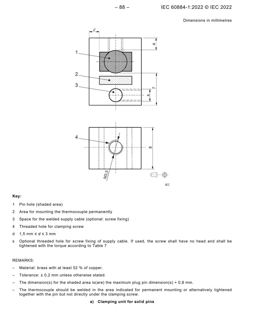
Figure 3-1
Hollow-pin clamping element, see Figure 3-2 (taken from the IEC standard).
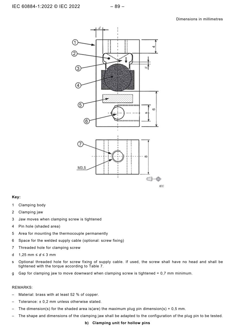
Figure 3-2
3.2 Photographs of the Actual Object
Solid-pin clamping element; see Figure 3-3.
| Number | Note |
| ① | Pin hole: the maximum pin size plus 0.8 mm |
| ② | Per the standard diagram, permanently secure the thermocouple in the correct position and solder the power leads. |
| ③ | Clamping Screw |
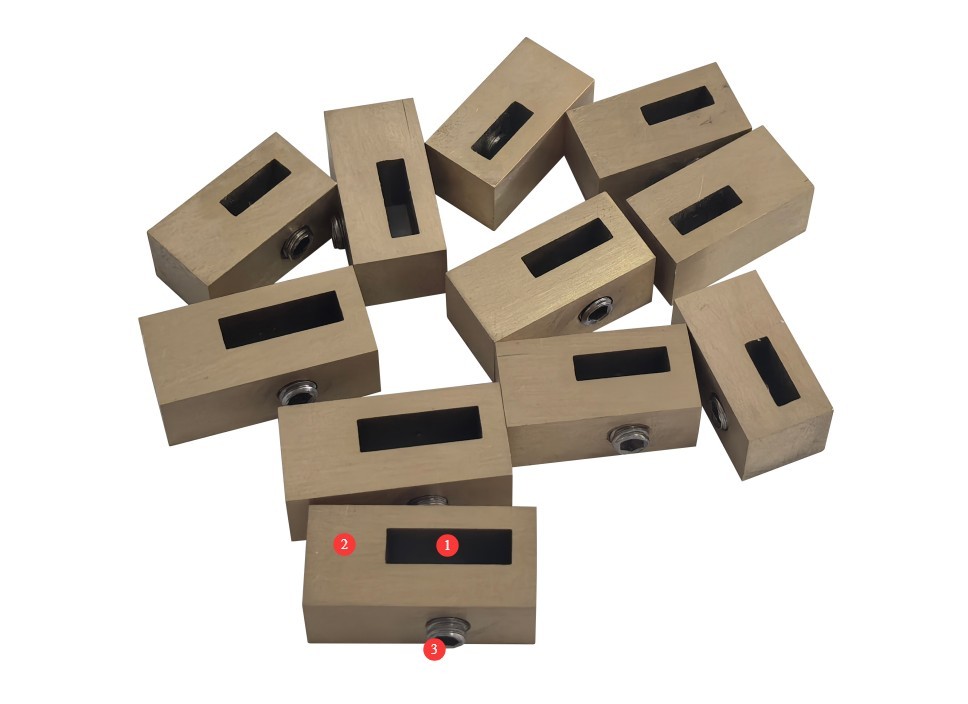
Figure 3-3
4. Preparations Before the Test
4.1 Preparation of Equipment and Tools
| Project | Note |
| Test Equipment Preparation | The LISUN WS Series Temperature Rise Tester may be used. It can output stable AC/DC current with an accuracy of ±1%, meeting the test current requirements specified in Table 18 (typically 1.25 times the rated current); it includes 8 K-type thermocouple channels and real-time temperature display functionality. |
| Torque Tools | Torque screwdriver (accuracy ±5%), capable of applying a torque of 0.8 N·m to tighten screws as required; the tool must be calibrated within its validity period. |
| Auxiliary Tooling | 500 mm × 500 mm × 20 mm dried wooden board (for holding the plug), copper conductor with the corresponding cross-sectional area (selected according to Table 16) |
4.2 Sample Pretreatment
Detachable-cord plug: Select a PVC-insulated copper conductor with the appropriate cross-sectional area as specified in Table 16 (flexible conductors for portable accessories, rigid conductors for fixed accessories); strip the wire to a length suitable for the terminal; and tighten the terminal screws to 2/3 of the torque value specified in GB/T 2099.1-2021 (IEC 60884-1:2022), and ensure good electrical contact.
5. Temperature Rise Test for Plugs and Sockets
5.1 Pin Fastening
Position the clamping screw in the middle of the metal portion of the plug pin (avoid contact with the insulation).
Use a torque screwdriver to tighten the screws to a standard torque of 0.8 N·m, ensuring that the plug makes firm contact with the clamping device and is secure (insufficient torque can result in high contact resistance and excessive temperature rise; excessive torque can damage the plug).
5.2 Thermocouple Installation
The thermocouple must be secured in the designated area of the clamping element or clamped together with the pin, but must not be positioned directly beneath the clamping screw (to prevent the screw from conducting heat and interfering with the temperature measurement).
The thermocouple must make tight contact with the clamping element or pin; we recommend securing it with solder or thermal adhesive to ensure accurate temperature response.
At the same time, install an ambient temperature thermocouple in a location free from interference, 1 meter away from the test setup, to monitor changes in ambient temperature throughout the entire process.
5.3 Test Setup
Place the plug, with the clamping device and thermocouple attached, in the center of a 500 mm × 500 mm × 20 mm dry wooden board, ensuring that the plug’s prongs point downward and the clamping device hangs freely without touching the board or any other objects.
The entire device is placed in an environment free of air currents to prevent convective airflow from fans, doors, and windows from affecting heat dissipation (convective airflow can result in an artificially low temperature rise, which does not reflect actual operating conditions).
5.4 Setting the Test Current
Connect the power supply cables of each clamping device to the test power circuit. The conductor lengths must meet the following requirements: the length of a single-conductor cable must be ≥1 m; the length of the conductor between the terminals of a two-pole plug must be ≥2 m (as required by Note 1 of the standard).
Set the test current (typically 1.25 times the rated current) as specified in Table 18 of IEC 60884-1:2022. For multi-pole plugs, the following circuits must be tested separately: current flowing through the phase contact; current flowing through the neutral contact and the adjacent phase contact; current flowing through the ground contact and the nearest phase contact.
5.5 Power-On Testing and Data Collection
After verifying that all connections are correct, the thermocouple signal is normal, and there are no short circuits or open circuits, turn on the test power supply, set the output current, and start the timer; the test lasts for 60 minutes.
Data Collection Requirements: Record the temperature values of each thermocouple once every minute, including the temperature of the clamping device and the ambient temperature; focus on monitoring the temperature rise of the clamping device, calculated as follows: Temperature Rise = Maximum Temperature of the Clamping Device – Average Ambient Temperature During the Test; Standard Limits: The temperature rise must not exceed 45 K (where the temperature rise value ΔK is equal to the value Δ°C). If any measurement point exceeds the temperature limit at any time during the test, the test is deemed a failure; there is no need to wait until the end of the test.
Multi-circuit testing: After changing the test circuit, repeat the setup steps described above to ensure that the heat dissipation conditions are consistent for each test.
5.6 End of the Test
Wait until the fixture and sample have cooled completely to room temperature—a cooling time of 20 to 30 minutes is recommended—before disassembling the fixture and disconnecting the wires to prevent burns from high temperatures.
6. Routine Maintenance and Care
6.1 Routine Maintenance
After each use and once the clamping element has returned to room temperature, use a lint-free, soft cloth to wipe the inner walls of the latch holes, the clamping contact surfaces, and the outer surfaces of the fixture to remove metal dust, copper shavings, insulation debris, and light oil stains.
Unscrew the clamping screw and use a soft nylon brush to clean the copper dust and oil residue from the internal threaded hole and the external threads of the screw.
6.2 Long-Term Storage and Maintenance
After regular maintenance is complete, cover the entire unit with a dust cover and store it in a dry, well-ventilated warehouse. Avoid moisture and condensation (brass is highly susceptible to moisture, which causes it to oxidize and turn black).
6.3 Calibration Interval Requirements
To ensure the accuracy and reliability of the device, it is recommended that it be sent periodically to a qualified third-party metrology laboratory for calibration. The recommended calibration interval is 12 months. The specific calibration interval may be determined by the user based on frequency of use, environmental conditions, and quality system requirements.
7. Troubleshooting and Resolution of Common Problems
| Fault Symptoms | Possible Causes | Procedure |
| Unstable torque output from the clamping screws; values fluctuate | Stuck threads, buildup of debris | Clean as described in Section 6.1. |