
 English
 中文简体
中文简体 English
 Русский
 Español
 Português
 Türkçe
 العربية
 Deutsch
 Polski
 Italiano
 Français
 한국어
한국어 ไทย
ไทย Tiếng Việt
 日本語
日本語





























Bending Apparatus for non-Metallic and Composite Conduits
User's Manual
Applicable LISUN models: LS-B52
1. Basic Understanding of Equipment
1.1 Key Parameters
| Parameters | Note |
| Nominal Diameter of the Sample Conduit | 16, 20, 25 mm |
| Radius at the bottom of the mold cavity | 48, 60, 75 mm |
| The radius of the arc described by the center of a curved roller | 84105, 131.25 mm |
| Groove Radius of Forming Dies and Bending Rolls | 8.1, 10.1, 12.6 mm |
| Diameter at the bottom of the bending roller | 24, 30, 37.5 mm |
This device is designed for specialized testing of the mechanical properties of non-metallic cable conduits.
It is primarily used in electrical product testing laboratories, quality control departments at cable and conduit manufacturers, third-party testing organizations, and for import and export product inspections.
1.2 Applicable Standards
Strictly in accordance with GB/T 20041.21-2017 “Conduit Systems for Cable Management—Part 21: Special Requirements for Rigid Conduit Systems,” and Figure 10.4.102 (corresponding to Clause 10.4.102 and Figure 103 of IEC 61386-21:2021), and subjected to testing.
1.3 Downloading Electronic Documents
We have already sent the download links for the electronic user manual, calibration certificate, warranty card, and other documents via email at the time of shipment. Please download them promptly. If you have not received the email, please contact us to request the download links again.
2. Precautions for Use
2.1 Operating Environment Safety Requirements
Operating environment temperature: 15°C to 35°C; relative humidity: 45% to 75%; no condensation, no corrosive gases, and no airborne dust.
Place the device on a level, stable workbench with at least 30 cm of clearance on all sides, away from sources of vibration.
2.2 Safety Guidelines for Operational Procedures
During testing, do not reach into the test area with your hands or any other part of your body to prevent crush injuries.
The test specimen must be securely mounted to prevent it from falling or ejection during loading, which could pose a safety hazard.
3. Introduction to the Test Setup
3.1 Standard Diagram
See Figure 3-1 (taken from the IEC standard).
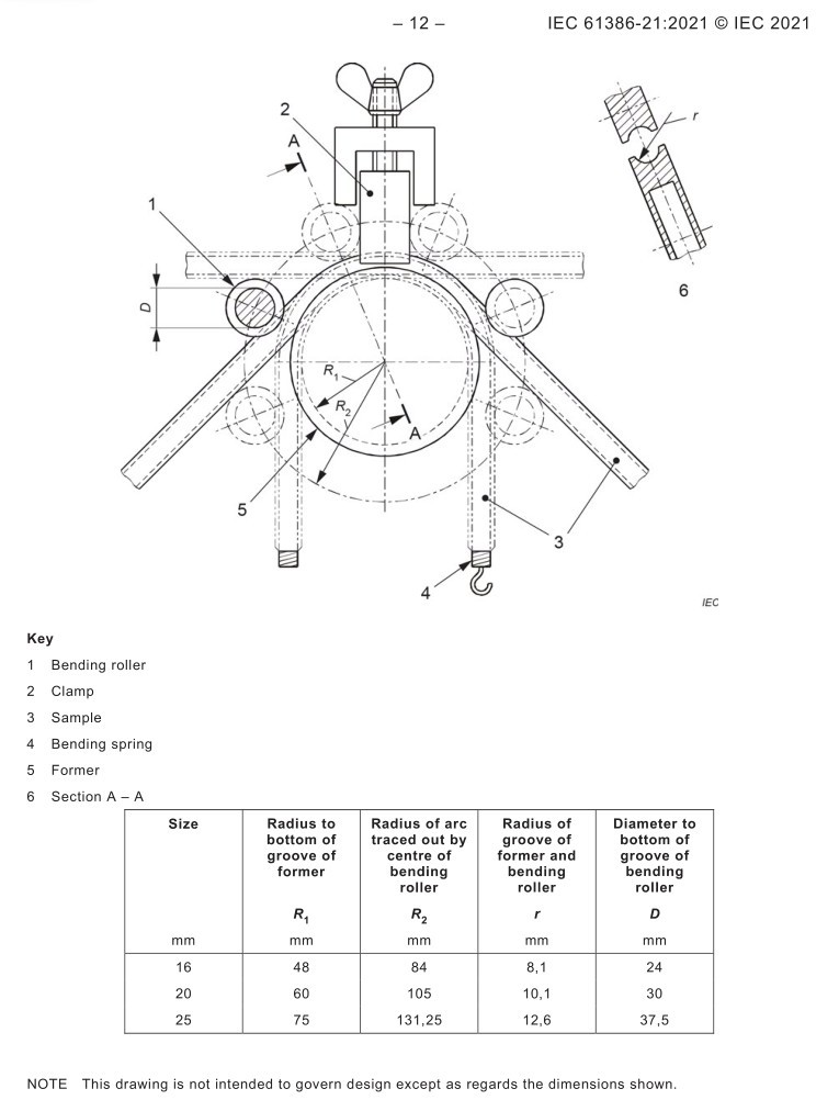
Figure 3-1
3.2 Product Photos
See Figure 3-2.
| Number | Note |
| ①②③ | Specimen mounting holes, available in 16, 20, and 25 mm sizes |
| ④⑤⑥ | Molding Die |
| ⑦⑧⑨ | Curved Rollers |
| ⑩ | Curved roller handle: Pull the handle down to bend the installed tubing. |
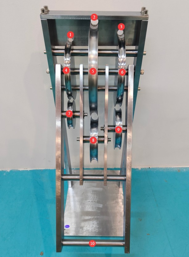
Figure 3-2
4. Catheter Bending Test
4.1 Sample Pretreatment
The length of the test specimen is approximately 500 mm; tests using specimens of other dimensions should be conducted in accordance with the manufacturer’s instructions.
Before the bending test, the bending aid shall be inserted into each test specimen. The bending aid shall consist of a spring formed by coiling a square-section metal wire; the spring shall be free of burrs, and its outer diameter shall be 0.7 mm to 1.0 mm smaller than the specified minimum inner diameter of the catheter; alternatively, a bending aid recommended by the manufacturer may be used.
Before the test, place the specimen, which has been fitted with the bending aid, in a freezer for at least 2 hours. The temperature of the freezer should be maintained at the values shown in the table below (with a tolerance of ±2 °C).
| Catheter Classification | Transportation, installation, and operating temperatures must not be lower than (unit: °C) |
| 1 | +5 |
| 2 | -5 |
| 3 | -15 |
| 4 | -25 |
| 5 | -45 |
4.2 Test Execution
The bending apparatus should be placed next to the freezer, and the test should be conducted within 12 seconds of removing the specimen from the freezer.
First, lift the bending roller handle so that the test specimen passes through the mounting hole and is placed in the groove of the forming die; simultaneously, gently clamp it with the clamping device. Next, gently press down on the bending roller handle and move the bending roller around the forming die. Upon releasing the bending roller, the specimen should be bent to (90±5)°. At the same time, the bending aid should be removable without damaging the specimen or the bending aid itself.
4.3 Evaluation of Test Results
After testing, the specimen must not exhibit any cracks visible to the naked eye or with corrected vision without additional magnification; furthermore, it must allow the corresponding gauge shown in Figure 4-1 (taken from the IEC standard) to pass through the tube under its own weight without any initial velocity.
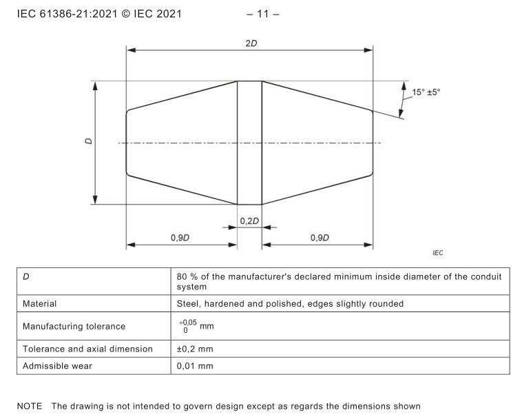
Figure 4-1
5. Post-Test Procedures
5.1 Device Reset
Outside of testing hours, do not install test specimens in the testing equipment to prevent the application of force when testing is not in progress.
5.2 Sample Preparation
Separate the samples that passed and failed the test, label them clearly, and avoid any confusion.
5.3 Cleaning and Tidying Up the Test Site
Wipe dust and debris from the surface of the device with a lint-free, soft cloth; do not rinse the equipment directly with water.
Organize the tools on the workbench, arrange them neatly, and clean up any debris generated during the experiment.
6. Routine Maintenance and Care
6.1 Regular Maintenance
Every three months, apply a small amount of neutral grease to the bending roller shaft to prevent rust and seizing; apply rust-preventive oil to the forming die and bending rollers to prevent rust.
6.2 Long-Term Storage and Maintenance
After completing routine maintenance, cover the entire unit with a dust cover and store it in a dry, well-ventilated warehouse.
6.3 Calibration Interval Requirements
To ensure the accuracy and reliability of the device, it is recommended that it be sent periodically to a qualified third-party metrology laboratory for calibration. The recommended calibration interval is 12 months. Users may determine the specific calibration interval based on frequency of use, environmental conditions, and quality system requirements.
7. Troubleshooting and Resolving Common Problems
| Fault Symptoms | Possible Causes | Procedure |
| Jamming of the Curved Roller | Dust buildup, insufficient lubrication, foreign objects lodged in the mechanism | Try again after removing dust, replenishing lubricant, and clearing any foreign objects from the gaps. |