
 English
 中文简体
中文简体 English
 Русский
 Español
 Português
 Türkçe
 العربية
 Deutsch
 Polski
 Italiano
 Français
 한국어
한국어 ไทย
ไทย Tiếng Việt
 日本語
日本語





























Retention Tensile Force Test Device for Soft Cable
User's Manual
Applicable LISUN models: LS-B07
1. Basic Understanding of Equipment
1.1 Key Parameters
1.1.1 Equipment Technical Specifications
| Parameters | Note |
| Touchscreen Display | Color Touchscreen + PLC |
| Drive Type | Gear Motor |
| Eccentric Wheel | Effective diameter: φ125 mm |
| Eccentricity of an Eccentric Wheel | 32.5 mm |
| Distance from the specimen to the fulcrum | 200 mm |
| Distance from the sample to the point of impact on the eccentric wheel | 160 mm |
| Weights | 50N, 60N, 80N, 100N Set of Weights |
| Test Completion Alert | Audible and Visual Alarms |
1.1.2 Applicable Standards
The LS-B07 Retention Tensile Force Test Device for Soft Cable is designed and manufactured in strict accordance with Clause 23.2 and Figure 20 of GB/T 2099.1-2021 “Plugs and Sockets for Household and Similar Purposes—Part 1: General Requirements” (IEC 60884-1:2022, Clause 23.2, Figure 27).
It is primarily used in electrical product quality inspection laboratories, the quality control departments of flexible cable and electrical accessory manufacturers, third-party testing organizations, and for import and export product inspections.
1.2 Equipment Configuration Verification
1.2.1 Unpacking
When unpacking the device, handle it gently and avoid using sharp tools that could scratch the device’s casing. After unpacking, first inspect the exterior of the device to ensure there are no obvious deformations or dents, and that the buttons are not damaged or loose. If you notice any abnormalities with the device or its accessories, do not turn it on. Please contact us immediately.
1.2.2 Host and Accessories
| Number | Note |
| ① | LS-B07 Main Unit |
| ② | Power Cord |
| ③ | Weight sets, available in 50 N, 60 N, 80 N, and 100 N combinations |
1.2.3 Downloading Electronic Documents
We have already emailed you the download links for the electronic user manual, calibration certificate, warranty card, and other documents at the time of shipment. Please download them as soon as possible. If you have not received the email, please contact us to request the download links again.
2. Safety Precautions
2.1 Electrical Safety
Before connecting the power cord, verify that the supply voltage is AC 220 V ±10% and the frequency is 50 Hz or 60 Hz. You must use a three-prong outlet with a protective ground, and the protective ground resistance must be ≤4 Ω. Never cut or disconnect the protective ground wire, as doing so poses a risk of electric shock.
2.2 Environmental Safety
Do not use in environments with flammable or explosive materials, strong electromagnetic interference, high temperatures and humidity, or excessive dust levels. Place the equipment on a level, stable surface and ensure there is at least 0.5 m of operating space around it. Operating environment: temperature 15°C to 35°C, relative humidity 45% to 75%.
2.3 Operating Procedures
During the test loading process, do not reach into the area of the clamps or the tensile transmission mechanism with your hands or body to prevent injuries from pinching or falling objects; Test specimens must be securely clamped to prevent them from detaching or weights from falling during testing, which could cause safety incidents; it is strictly prohibited to disassemble the equipment’s transmission mechanism without authorization, adjust the motor speed improperly, or replace the original manufacturer’s counterweights.
3. Equipment Overview
3.1 Standard Diagram
See Figure 3-1 (taken from the IEC standard).
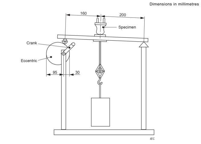
Figure 3-1
3.2 Product Photos
See Figure 3-2.
| Number | Note |
| ① | Power Switch |
| ② | Buzzer; a buzzer sounds when the test is complete |
| ③ | Touchscreen |
| ④ | Motor Power Switch |
| ⑤ | The motor speed control knob is pre-set at the factory; only minor adjustments in accordance with the test specifications are permitted (the standard tensile cycle is 1 second). Do not make significant adjustments at will. |
| ⑥ | Weights |
| ⑦ | Eccentric wheel, driven by a motor, no handle required |
| ⑧ | Specimen Mounting Holes |
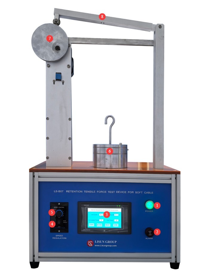
Figure 3-2
4. Introduction to the Touchscreen Program
4.1 Initial Screen
See Figure 4-1.
| Number | Note |
| ① | Go to the Test Interface |
| ② | Go to the Help screen |
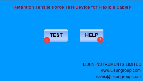
Figure 4-1
4.2 Test Interface
See Figure 4-2.
| Number | Note |
| ① | Duration of the last test cycle |
| ② | Duration of the current test cycle |
| ③ | Number of tests conducted so far |
| ④ | Set the number of tests |
| ⑤ | Start/Stop Test |
| ⑥ | Inch movement; click to adjust the position of the eccentric wheel |
| ⑦ | Reset: Clear current test data and clear the buzzer alarm |
| ⑧ | Return to the Home Screen |
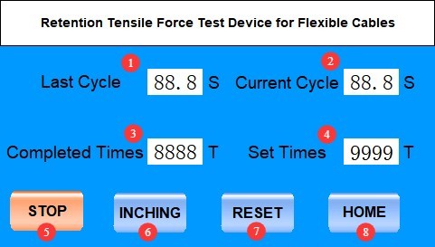
Figure 4-2
5. Flexible Cable Retention Force Test
5.1 Sample Preparation
Select brand-new, unused finished plugs and receptacles that have not undergone any destructive testing, and discard any nonconforming specimens with surface dents, cracks, or obvious deformation.
The flexible cable should be naturally straight, free of twists or kinks; when part of the outer jacket is stripped, the insulation of the flexible cable itself must not be damaged.
5.2 Determining the Duration of the Test Cycle
See Sections 3.2 and 4.2. Turn on the machine and perform an idle test to verify that the test cycle lasts 1 second (the standard requires that the tensile force be applied for 1 second each time). If the cycle is not 1 second, slowly adjust the motor speed control knob until the test cycle is 1 second.
5.3 Preparation of Weights
Prepare the corresponding weights according to the table below.
| Rated Voltage and Current of Flexible Cables | Weights |
| Rated current = 2.5 A | 50 N |
| 2.5 A < rated current ≤ 20 A, rated voltage ≤ 250 V | 60 N |
| 2.5 A < rated current ≤ 20 A, rated voltage > 250 V | 80 N |
| Rated current > 20 A | 100 N |
5.4 Installation and Calibration of the Specimen Weights
Refer to the standard diagram in Section 3.1 to install the test specimen’s flexible cable and the weight. Refer to Section 4.2 to use the inch-feed function; when the eccentric wheel reaches the lower limit, the weight should drop naturally without any additional tensile force; during the remainder of the travel, the weight should remain suspended off the ground, and a standard tensile force should be continuously applied.
5.5 Set Parameters and Start the Test
| Instructions | Note |
| ① | Refer to Section 4.2 and set the number of test cycles to 100 (the standard requires the specimen to withstand 100 tensile cycles). |
| ② | Click “Reset” to clear the current test data |
| ③ | Click “Start” to begin the test |
| ④ | During the test, observe the condition of the specimen and the weights. If you notice any abnormalities, click “Stop,” readjust the setup, and try again. |
| ⑤ | When the test is complete and the device sounds an alarm, click “Reset” to clear the current test data and silence the buzzer. |
5.6 Post-Test Procedures
After the test is completed, refer to the standard to conduct follow-up torque tests (using the LS-B47 Flexible Cables Torque Test Device) and inspect the displacement of the flexible cable to determine whether it complies with the standard.
6. Routine Maintenance and Care of Equipment
6.1 Daily Maintenance After Shutdown
At the end of each day’s testing, clean dust and specimen debris from the equipment surfaces, and keep the fixtures and slide rails clean and free of debris; clean the touchscreen with a dedicated screen-cleaning cloth; and check that the hooks are not loose or deformed.
6.2 Weekly Routine Maintenance
Apply a small amount of specialized lubricating grease to the equipment’s guide rails and lead screws to ensure smooth, jam-free operation.
6.3 Maintenance During Long-Term Storage with the Machine Shut Down
After the equipment has been powered off and routine maintenance has been completed, cover the entire unit with a dust cover and store it in a dry, well-ventilated warehouse; coat the weights with rust-preventative oil and store them separately to prevent rust and deformation; power on the equipment for 30 minutes each month to prevent moisture damage to the components.
6.4 Calibration Interval Requirements
To ensure the measurement accuracy and operational reliability of the equipment, it is recommended that it be sent periodically to a qualified third-party metrology institution for calibration. The recommended calibration interval is 12 months. Users may determine the specific calibration interval based on frequency of use, environmental conditions, and quality system requirements.
7. Troubleshooting and Resolving Common Problems
| Fault Symptoms | Possible Causes | Procedure |
| The device did not respond after the test was started | The motor power switch is not turned on | The unit has two power switches; please make sure the motor switch is also turned on before trying again. |
| Touchscreen lags; no response to taps | Screen surface smudges causing interference; program crashes | Turn off the device, clean the screen, then restart it and try again. |