
 English
 中文简体
中文简体 English
 Русский
 Español
 Português
 Türkçe
 العربية
 Deutsch
 Polski
 Italiano
 Français
 한국어
한국어 ไทย
ไทย Tiếng Việt
 日本語
日本語





























Test Wall For Concealed Socket IP Waterproof
User's Manual
Applicable LISUN models: LS-B05
1. Basic Understanding of Equipment
1.1 Basic Equipment Properties
This device is suitable for all types of residential and industrial flush-mounted and semi-flush-mounted waterproof outlets.
It is primarily used in electrical appliance quality inspection laboratories, the quality control departments of electrical outlet manufacturers, third-party testing organizations, and for import and export product inspections.
1.2 Applicable Standards
Strictly in accordance with Clause 16.2.3 and Figure 15 of GB/T 2099.1-2021, “Plugs and Sockets for Household and Similar Uses—Part 1: General Requirements” (IEC 60884-1:2022, Clause 16.2.3, Figure 18).
Primarily used for testing the IP-rated water resistance and splash resistance of flush-mounted and semi-flush-mounted wall-mounted outlets under simulated conditions, this test simulates the conditions in which the outlet, after being installed in a wall, is exposed to rainwater and household splashes, to determine whether the outlet’s waterproof sealing performance meets the standard requirements.
1.3 Downloading Electronic Documents
We have already sent the download links for the electronic user manual, calibration certificate, warranty card, and other documents via email at the time of shipment. Please download them as soon as possible. If you have not received the email, please contact us to request the download links again.
2. Precautions for Use
The test wall is designed to simulate a wall structure and weighs approximately 80 kg. When moving it, multiple people must work together and handle it with care to prevent damage to the equipment and avoid safety incidents;
Before testing, the socket under test and its accompanying cable must be securely installed and fastened in the test wall junction box in accordance with the standard requirements;
Ensure that the weight of the test wall falls within the rated load capacity of the sample stage on the waterproof testing equipment to prevent damage to the equipment, the test wall from falling, and accidental injury to personnel;
Place the test wall steadily in accordance with the specifications for waterproof testing equipment to prevent collisions or slippage.
3. Equipment Overview
3.1 Standard Diagram
See Figure 3-1.
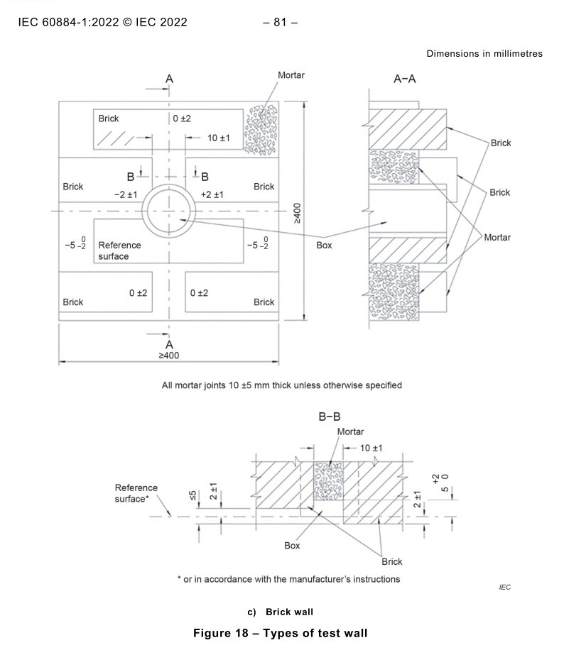
Figure 3-1
3.2 Product Photos
See Figures 3-2 and 3-3.
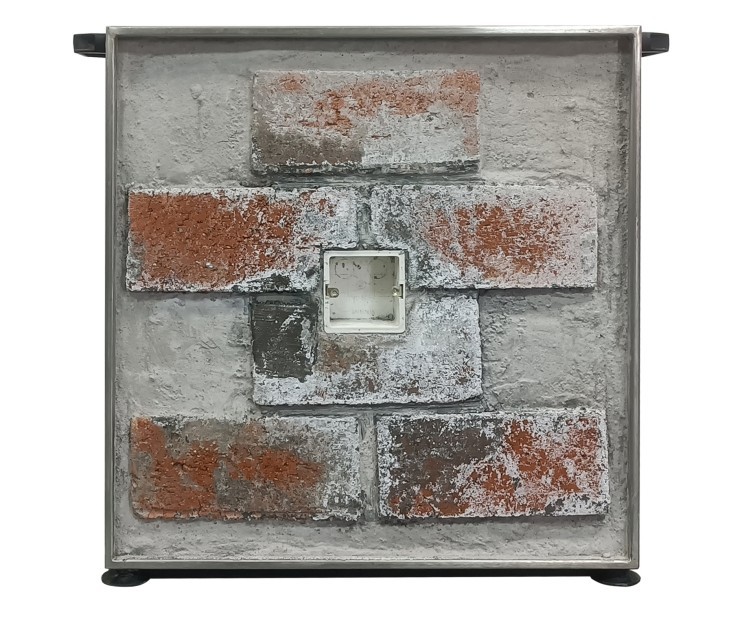
Figure 3-2
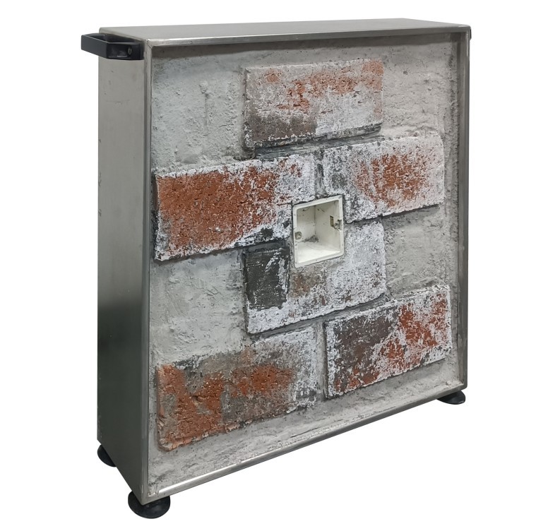
Figure 3-3
4. Use of Test Walls
4.1 Preliminary Preparations for the Socket Under Test
The appearance of the concealed electrical outlet under test should show no damage or cracks; the mounting clip structure should be intact; and it should not have undergone any destructive testing.
Use a lint-free, dry cloth to wipe away dust and debris from the surface of the socket, ensuring that the sample is dry and clean, with no moisture remaining on the surface.
4.2 Installation and Securing of the Socket Samples Under Test
Align the pre-processed flush-mounted outlet with the standard installation box on the test wall, and gently slide it into place so that it fits snugly against the test wall.
Adjust the adjustable clips on both sides to secure the socket frame. Gently press to ensure the socket is firmly installed, with no looseness or misalignment, and that the sealing strip fits snugly without any gaps.
Test the outlet without any plugs inserted; if it has a cover, close the cover before testing. Be careful not to move, bump, or shake the outlet assembly, as this may affect the test results.
4.3 Test Procedures for IP Water Resistance Standards
4.3.1 IPX3/IPX4 Water Resistance Testing
See Figure 4-1 for the placement of the test wall and waterproofing test equipment.
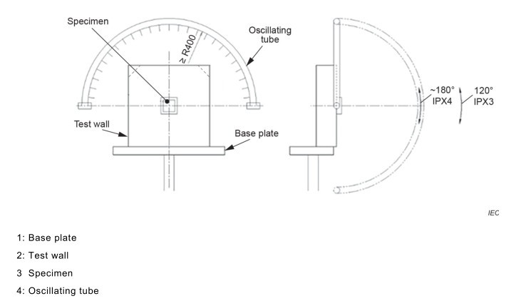
Figure 4-1
For the test procedure, please refer to standard GB/T 4208-2017 (IEC 60529:2013).
4.3.2 Waterproofing Tests for Other Grades
Placement tests were conducted in accordance with the relevant requirements of the reference standard GB/T 4208-2017 (IEC 60529:2013).
4.4 Post-Test Procedures
If the electrical accessory has an open drainage hole, the observations should confirm that water entering the test specimen does not accumulate but is drained before it can cause damage to the entire receptacle assembly.
Within 5 minutes after completion of this test, the receptacle shall undergo the electrical strength test specified in Clause 17.3 of GB/T 2099.1-2021 (Clause 17.3 of IEC 60884-1:2022).
5. Daily Maintenance and Care of Equipment
5.1 Daily Maintenance After Use
After each use, wipe down the entire surface of the equipment to remove water spots, dust, and limescale residue from spraying, and keep it looking clean.
Wipe up any standing water around the equipment to keep the area dry and slip-resistant.
5.2 Maintenance During Long-Term Non-Use
Thoroughly wipe any water stains from the surface of the equipment and store it in a well-ventilated, dry indoor environment.
Cover the entire piece of equipment with a dust cover to prevent dust and moisture from corroding the metal parts.
5.3 Calibration Interval Requirements
To ensure the measurement accuracy and operational reliability of the equipment, it is recommended that it be sent periodically to a qualified third-party metrology laboratory for calibration. The recommended calibration interval is 12 months. Users may determine the specific calibration interval based on usage frequency, environmental conditions, and quality system requirements.