
 English
 中文简体
中文简体 English
 Русский
 Español
 Português
 Türkçe
 العربية
 Deutsch
 Polski
 Italiano
 Français
 한국어
한국어 ไทย
ไทย Tiếng Việt
 日本語
日本語





























UV Lamp Test System
User's Manual
Applicable LISUN models: LMS-9000CUV、LMS-9000CUV-VIS、LPCE-2(LMS-9000CUV)
1. Basic Understanding of Equipment
1.1 Unboxing and Inspection
When unpacking the device, handle it gently to avoid scratching the outer casing with sharp tools. After unpacking, first inspect the exterior of the device to ensure there is no visible deformation or dents, and that the buttons are not damaged or loose. If you notice any abnormalities with the device or its accessories, do not turn it on. Please contact us immediately.
1.2 Core Hardware Components
See Figure 1-1.
| Number | Note |
| ① | High-Precision UV Spectroradiometer, Model LMS-9000CUV |
| ② | Quartz UV Optical Fiber Cable, Model CFS-1.5M |
| ③ | USB Cable |
| ④ | Dedicated Power Supply for UV Standard Light Sources, Model SLS-UV-P |
| ⑤ | Ultraviolet Standard Light Source, Model SLS-UV |
| ⑥ | Connecting rod, used for mounting a UV Standard Light Source |
| ⑦ | Power cord, used to connect the dedicated power supply for the UV Standard Light Source to the test dark box |
| ⑧ | Test Chamber, Model CASE-UV036 |
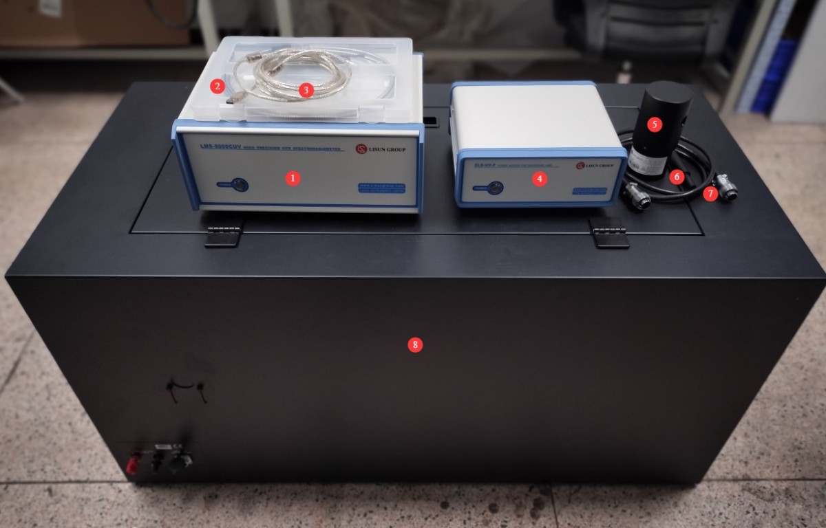
Figure 1-1
1.3 Downloading Electronic Documents
We have already sent download links for the electronic user manual, software, warranty card, and other materials via email at the time of shipment. Please download them as soon as possible. If you missed the email, please feel free to contact us to request the download links again.
2. Precautions for Use
2.1 Environmental Safety
The equipment must be placed in a dry, well-ventilated environment free of dust and corrosive gases;
Ambient temperature: 15–35°C; relative humidity: ≤65% (no condensation);
Keep the equipment away from strong magnetic fields and strong electric fields.
2.2 Operating Procedures
The natural service life of an ultraviolet standard lamp is 1 year; it is recommended that it be replaced when it reaches the end of its service life to avoid affecting test accuracy;
Optical Fiber must not be bent excessively (bending radius ≥ 10 cm). Do not step on or crush the Optical Fiber, as this may cause damage and result in abnormal test results.
2.3 Protection from Direct UV Rays
This equipment is used for testing ultraviolet light sources. Direct exposure to ultraviolet light can cause burns and irreversible damage to the eyes and skin. Under no circumstances should you look directly at the ultraviolet light source or allow ultraviolet light to shine directly on your body during operation.
2.4 Other
For matters not covered in this manual, please proceed with caution or contact us.
3. Equipment Overview and Connections
The LMS-9000CUV is a Spectroradiometer used for testing; the CASE-UV036 is a test chamber used to provide the testing environment. This primarily concerns the connection between these two devices.
3.1 Introduction to and Wiring of the LMS-9000CUV
3.1.1 Introduction to the Front Panel
See Figure 3-1. The front panel of the device includes the device’s power switch.
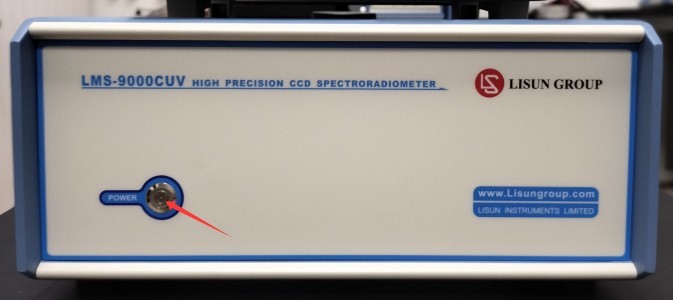
Figure 3-1
3.1.2 Introduction to the Back Panel
See Figure 3-2.
| Number | Note |
| ① | Optical Fiber interface; connect via Optical Fiber cable to the test anechoic chamber |
| ② | USB port: Connects to a computer via a USB cable to communicate with computer software and power the device. |
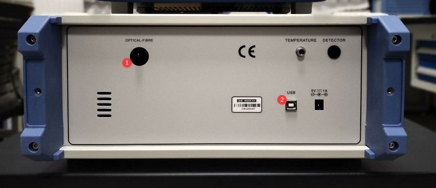
Figure 3-2
Note: The other ports are for backup purposes only; there is no need to connect to them.
3.2 Introduction to the Test Chamber and Wiring
3.2.1 Optical Fiber Connections
Optical Fiber connection interface; see Figure 3-3.
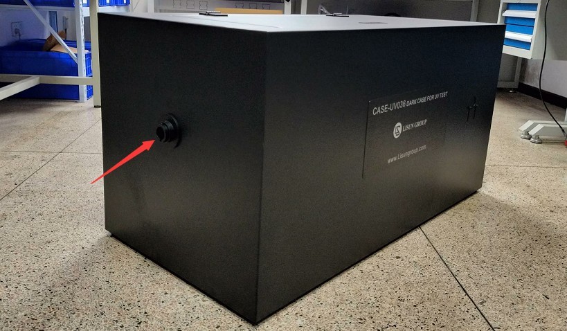
Figure 3-3
Once the Optical Fiber connection is complete, see Figure 3-4.
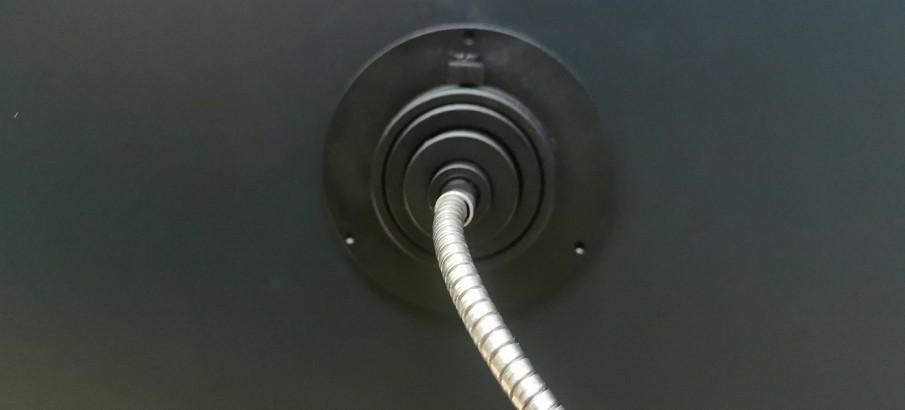
Figure 3-4
3.2.2 Testing the Appearance of the Test Chamber and Other Interfaces
See Figures 3–5.
| Number | Note |
| ① | Light box cover; open to view the interior and install lighting fixtures |
| ② | Mounting holes for linear light fixtures |
| ③ | Terminals for the Sample Luminaire Power Cord |
| ④ | Standard Light Source Power Cord Connector |
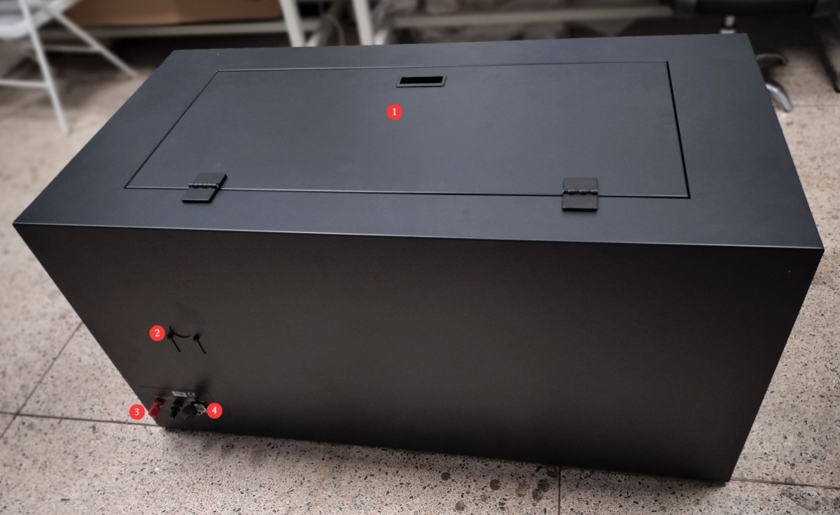
Figure 3-5
4. Software Installation and Overview
4.1 Software and Driver Installation
4.1.1 Software Runtime Environment
System Requirements: Windows 7/8/10/11 (32-bit/64-bit); the computer must have at least one USB port.
Note: If you have purchased multiple LMS-9000 series Spectroradiometers, please connect them to different computers whenever possible and avoid mixing them, as doing so may cause the software to display incorrect data.
4.1.2 Installation
See Figure 4-1.
| Number | Note |
| ① | LMS-9000CUV software installation file—please double-click to install |
| ② | LMS-9000CUV Driver—Please double-click to install |
| ③ | SLS-UV Ultraviolet Lamp Calibration File (Note: Each Standard Light Source has a different file), which must be used during system calibration |
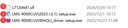
Figure 4-1
4.1.3 Exception Handling
If your antivirus software or Windows Firewall flags a file as suspicious during the software installation process, please temporarily disable the antivirus software or Windows Firewall and then try installing the software again.
If the software fails to open when you double-click the icon after a successful installation, please check whether you are logged in to your computer with an administrator account. If the software still does not open after logging in with an administrator account, right-click the software icon to open its Properties window. On the Compatibility tab, check the box next to “Run this program as an administrator” and click “Apply” (Figure 4-2), then double-click the icon again to open the software.
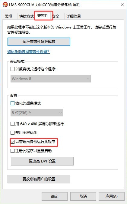
Figure 4-2
4.2 Initial Software Setup
4.2.1 Opening the Software
The first time you open the software, you will be prompted to create a new database file (in .lmsuvi format); subsequent test reports will be automatically saved to this database file. Please enter a file name, select an appropriate path, and click “Save.”
Note 1: The LMS-9000CUV software can be installed on any computer, but it will not function unless that computer is connected to an LMS-9000 device.
Note 2: Database files generated by the LMS-9000 software can only be opened using the LMS-9000 software.
Note 3: Please avoid placing database files on your computer’s desktop whenever possible, as this may cause errors when reading or writing data.
4.2.2 System Configuration
See Figure 4-3.
| Number | Note |
| ① | Click “System Configuration” |
| ② | Spectroradiometer models and related information; the software can automatically retrieve this data |
| ③ | Maximum automatic integration time: During testing, the integration time is set to “Auto” and is inversely proportional to the intensity of the mercury lamp being tested. It is recommended to use a longer maximum automatic integration time—such as 10000—to facilitate testing under low-light conditions. |
| ④ | The wavelength test range is set from 200 to 450 nm. Please verify that the display is correct; if not, please adjust it. |
| ⑤ | Click the drop-down list to select the model of the AC power supply you purchased (usually the LSP Series). If you did not purchase an LISUN AC power supply, please select “Not Installed”; otherwise, a communication error will occur. |
| ⑥ | Click the drop-down list to select the model of the DC power supply you purchased (usually the DC Series). If you did not purchase a LISUN DC power supply, please select “Not Installed”; otherwise, a communication error will occur. |
| ⑦ | Click the drop-down list to select the model of the power meter you purchased; you can find the model number on the power meter’s front panel. Please select the correct model you purchased. If you did not purchase a LISUN power meter, please select “Not Installed”; otherwise, a communication error will occur. |
| ⑧ | The standard test distance for the light box is 1 meter. If you change the actual test distance, please enter the correct test distance here; otherwise, the test data will be incorrect. |
| ⑨ | Please enter the correct area of the light-emitting surface of the sample luminaire. |
| ⑩ | Click to automatically search for the communication port. If an error message appears, please check the connection of the communication cable for the corresponding device according to the message. |
| ⑪ | Once all settings and communication are configured, simply click OK to save. |
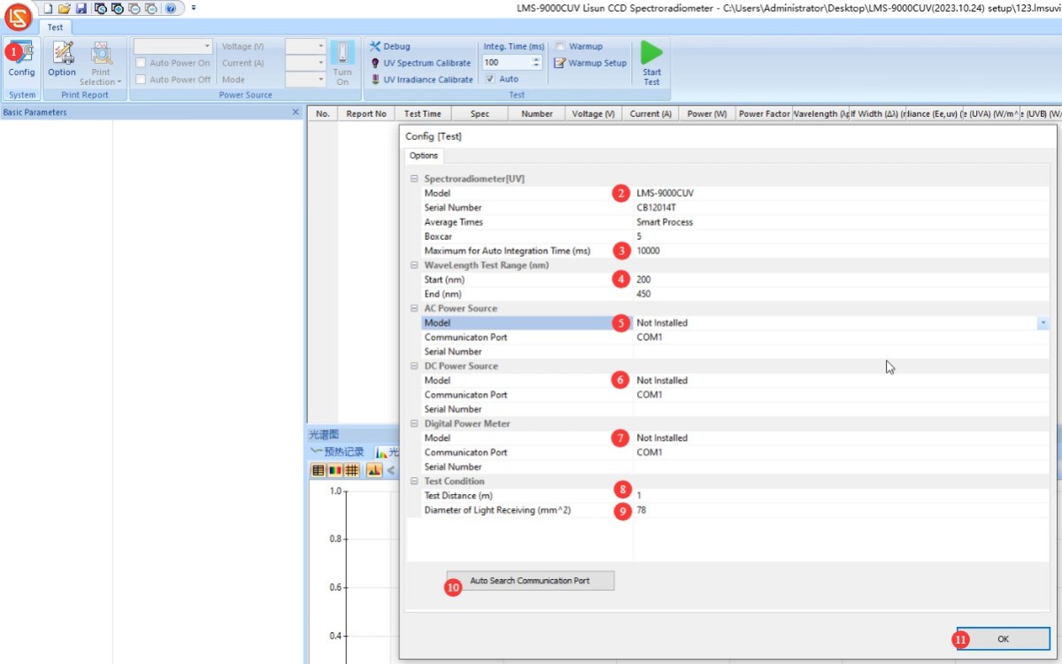
Figure 4-3
Note 2: Reinstalling the software or unplugging and replugging the USB cable may require re-establishing communication.
5. Calibration
5.1 Calibration Principles
| Description of the Situation | Is recalibration necessary? |
| First Use | Calibration is required before use. |
| The equipment is used frequently | It is recommended to calibrate at least once a month. |
| Equipment that has not been used for more than a month | Calibration is required before the next use. |
| Reinstall the software | No recalibration required |
| Replace the computer | Needs to be recalibrated |
| Plugging in and unplugging the USB cable | No recalibration required |
| Inserting and Removing the Optical Fiber at the End of a Spectroradiometer | |
| Inserting and Removing the Optical Fiber Probe from the Dark Box | It is recommended to recalibrate. |
| Significant changes in environmental conditions, such as temperature and humidity |
5.2 Calibration Procedure
5.2.1 Installation and Illumination of The Standard Light Source
See Figure 5-1 for the power connection for the SLS-UV-P ultraviolet Standard Light Source.
| Number | Note |
| ① | Connect the input power supply. Please follow the prompts to connect the SLS-UV-P to a suitable power source. |
| ② | Connect the output power cord to the test chamber. |
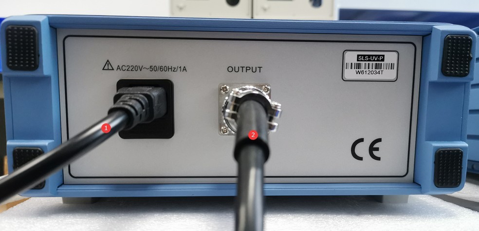
Figure 5-1
Use the connecting rod to mount the SLS-UV ultraviolet Standard Light Source to the dark box, and connect the power cord of the ultraviolet Standard Light Source inside the dark box to the Standard Light Source, as shown in Figure 5-2.
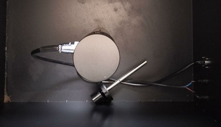
Figure 5-2
Turn on the SLS-UV-P and activate the UV Standard Light Source.
Adjust the orientation of the Standard Light Source’s light-emitting aperture so that it is directly aligned with the aperture in the aperture diaphragm and the Optical Fiber on the opposite side of the dark box. Then close the dark box cover, as shown in Figure 5-3.
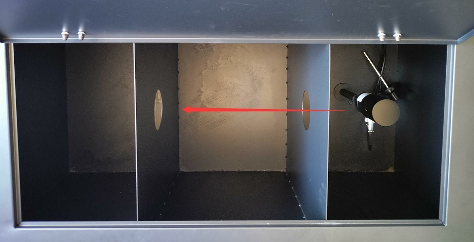
Figure 5-3
5.2.2 Calibration via the Software Interface
See Figure 5-4.
| Number | Note |
| ① | Click “UV Spectrum Calibrate” |
| ② | Our calibration documents use W/m²/nm; please select the correct unit. |
| ③ | Retrieve the calibration file with the .slf extension mentioned in Section 4.1.2 |
| ④ | When earning points, be sure to check “Automatic”/”Auto” |
| ⑤ | Average count—no need to change it; just use the default value. |
| ⑥ | Stabilization time for Standard Light Sources: UV Standard Light Sources require at least 10 minutes to stabilize; a stabilization period of 10 to 15 minutes is recommended. Calibration can only be performed after the Standard Light Source has stabilized. |
| ⑦ | After confirming that the settings are correct, click Start. |
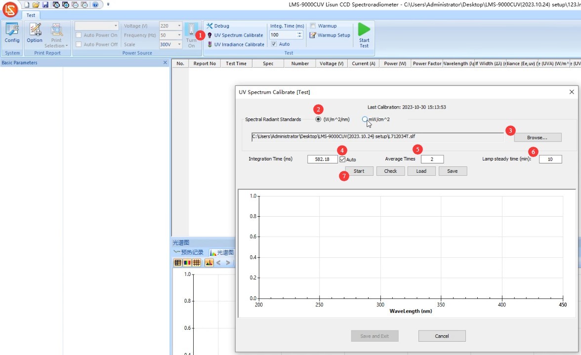
Figure 5-4
When the countdown ends, the software automatically performs calibration, as shown in Figure 5-5.
| Number | Note |
| ① | Calibration Complete |
| ② | Relative Spectral Curves of Ultraviolet Standard Light Sources |
| ③ | Click “Save and Exit” |
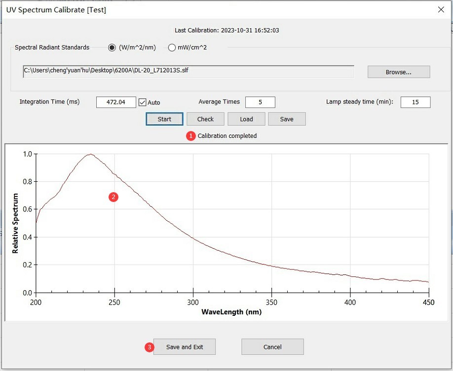
Figure 5-5
5.2.3 Removal of The Standard Light Source
Turn off the dedicated power supply for the SLS-UV-P ultraviolet Standard Light Source, disconnect the Standard Light Source cable, wait for the Standard Light Source to cool down, then remove the Standard Light Source and its connecting rod and store them properly.
6. Testing
6.1 Installing and Powering On the Sample Light Fixture
6.1.1 Installation of Sample Luminaires
We offer models with E27 sockets, as shown in Figure 6-1.
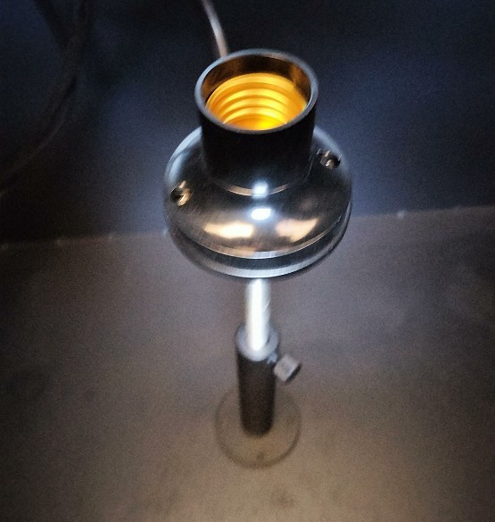
Figure 6-1
When testing linear luminaires, refer to Section 3.2.2 for installation instructions. For other types of luminaires, secure the light-emitting surface of the luminaire at the standard test position 1 meter from the Optical Fiber, with the light-emitting surface facing the aperture of the light shield and the Optical Fiber. If you need to adjust the actual test distance, refer to Section 4.2.3 to enter the correct test distance into the software.
6.1.2 Turning On the Test Luminaire
Refer to Section 3.2.2, connect the sample luminaire to a suitable power source, turn it on, and then close the test chamber lid.
Note: If you have a LISUN power supply, you can use the LMS-9000C software to control the power supply output (Figure 6-2). If you are using your own power supply, please control it manually and turn on the sample lamp.
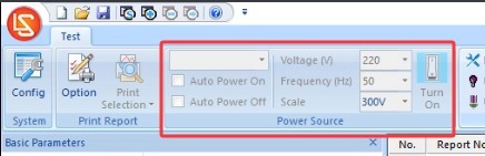
Figure 6-2
6.2 Software Operation
6.2.1 Setting the Units of Irradiance
Click the red LISUN logo in the upper-left corner of the software interface, then click the “List Setup” drop-down menu, as shown in Figure 6-3.
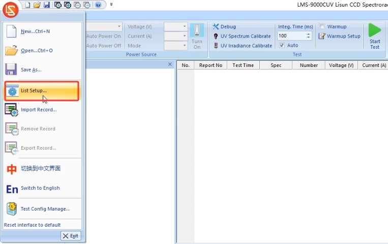
Figure 6-3
The default unit for irradiance is W/m². Check the option shown in the figure below to change the unit to mW/cm², as shown in Figure 6-4.
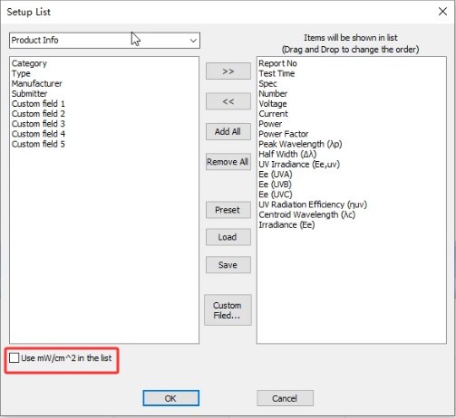
Figure 6-4
6.2.2 Preheating Parameter Settings
See Figure 6-5.
| Number | Note |
| ① | Click “Preheating Parameter Settings” |
| ② | Warm-up Duration Setting: The purpose of the warm-up is to allow the light fixture to remain on for a period of time until its luminous and color parameters stabilize, after which the test proceeds automatically. |
| ③ | Sampling interval: The software automatically takes samples at the set interval throughout the entire warm-up period to obtain real-time data. We recommend setting the interval to 5 seconds or longer. |
| ④ | If this box is checked, the test will begin automatically once the light fixture reaches a stable state, skipping the remaining warm-up time; if this box is not checked, the test will begin only after the warm-up period has elapsed as set. |
| ⑤ | If this box is checked, test reports for all sampling points will be saved automatically; if it is unchecked, only the final test report will be saved automatically. |
| ⑥ | Definition of a luminaire’s steady state. If the values are set to 20 and 0.5%, the luminaire is considered to be in a steady state if the parameter has not varied by more than 0.5% over the past 20 minutes. |
| ⑦ | You can select which parameters the software should use to determine whether a light fixture is stable: optical parameters, electrical parameters |
| ⑧ | The software will save the change curves for the selected parameters during the warm-up period in the test report. |
| ⑨ | Once you’ve finished configuring the settings, click OK to confirm and exit. |
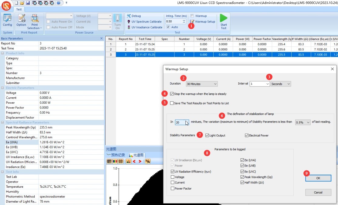
Figure 6-5
6.2.3 Confirm the test control parameters and conduct the test
See Figure 6-6.
| Number | Note |
| ① | Be sure to select “Automatic” for “Points Time,” otherwise the test results will be inaccurate. |
| ② | If you need to preheat, check the box; if not, leave it unchecked. |
| ③ | Click to run the test. If “Warm-up” is checked, the software will enter a warm-up countdown and display the current warm-up progress and data in the upper-right corner; if “Warm-up” is not checked, the software will run the test immediately and display the test results. |
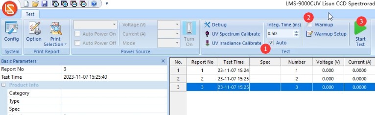
Figure 6-6
During the warm-up process, the software interface appears as shown in Figures 6 and 7.
| Number | Note |
| ① | This section displays the preheating progress, as well as the current preheating parameters and curve. |
| ② | Click to skip the warm-up and go straight to the test |

Figures 6–7
After the test is complete, turn off the power to the test lamp and remove it. Do not store lamps in the test chamber when not in use.
6.3 Test File Processing
See Figures 6–8.
| Number | Note |
| ① | After the test is complete, all test reports will be automatically saved in the current database file. |
| ② | To delete a test report from the database file, select the report and click “Delete.” |
| ③ | To make it easier to find test reports, click the blank button shown in the image below to create a new database file, and store reports for different luminaires in separate database files. After creating a new database file, you can proceed directly with testing without needing to recalibrate or reconfigure the system. |
| ④ | Click “Open” to open a previously saved database file. |
| ⑤ | Electrical Parameters: If you have purchased a LISUN power meter and successfully established communication as described in Section 4.2.3, the LMS-9000CUV will automatically retrieve the electrical parameters from the power meter; otherwise, you can enter the electrical parameters manually. |
| ⑥ | Click to set print options |
| ⑦ | Click to print the test report. The software automatically uses the printers installed on your computer, including PDF printers. |
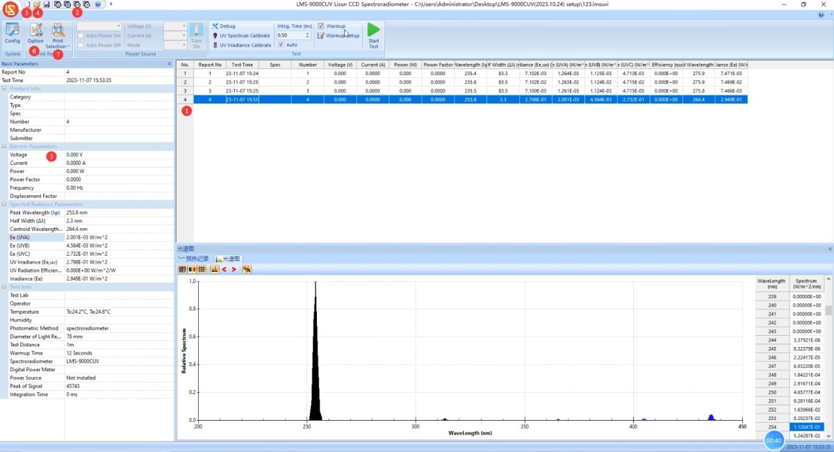
Figures 6–8
7. Daily Maintenance and Care of Equipment
7.1 Routine Hardware Maintenance
Check that all connections are secure and that the USB cables and Optical Fibres are not damaged;
Inspect the packaging of the Standard Light Source to ensure there is no moisture or damage, and verify the expiration date.
7.2 Long-Term Decommissioning and Maintenance
Thoroughly clean all equipment surfaces and cover all equipment with dust-proof cloths; store USB cables and Optical Fibers separately and securely;
Ensure that the laboratory is dry and well-ventilated to prevent equipment from becoming damp; if the ambient humidity is high, keep a dehumidifier on hand;
Run the system online once a month to ensure it is operating normally.
7.3 Calibration Interval Requirements
To ensure the measurement accuracy and operational reliability of the equipment, it is recommended that it be sent periodically to a qualified third-party metrology institution for calibration. The recommended calibration interval is 12 months. Users may determine the specific calibration interval based on frequency of use, environmental conditions, and quality system requirements.
8. Troubleshooting and Resolving Common Problems
| Fault Symptoms | Possible Causes | Procedure |
| The software won’t open | Not running as an administrator; software installation is incomplete | Right-click the software shortcut and select “Run as administrator”; uninstall the old software, delete any remaining folders, and then reinstall the software. |
| Software Communication Error | Driver not installed or installation failed; USB connection error | See Section 4.1.2 for driver installation; try a different USB port. |
| “Signal too weak” message appears during calibration or testing | “Auto” is not checked for the accumulation time, and the maximum automatic accumulation time is set too short | Refer to sections 5.2.2 and 6.2.3; be sure to select “Auto” for the integration time during calibration or testing. Refer to section 4.2.3 to set a longer maximum automatic integration time. If the signal is still too weak, the Optical Fiber may be damaged. |
| The electrical parameter is displayed as 0 | You have not purchased a LISUN power meter, or there is a communication error. | See Section 6.3 for automatically retrieving electrical parameters or manually entering them. |
| Software Encountered an Error Opening the Database File | The database file path does not exist, or the file is in use | See Section 6.3 for instructions on creating a new database file; do not store database files directly on your computer’s desktop. |