
 English
 中文简体
中文简体 English
 Русский
 Español
 Português
 Türkçe
 العربية
 Deutsch
 Polski
 Italiano
 Français
 한국어
한국어 ไทย
ไทย Tiếng Việt
 日本語
日本語





























Horizontal Vertical Flame Tester
User's Manual
Applicable LISUN models: HVR-LS、HVR-LSS
1. Unboxing and Basic Familiarization with the Equipment
1.1 Key Technical Specifications
| LISUN Model | HVR-LS | HVR-LSS |
| Product Name | With housing | Without a case |
| Testing Features | Supports horizontal and vertical combustion testing for HB& V-class (standard configuration: 50W copper block + thermocouple) and 5V-class (optional HVR-LSTH: 500W copper block + thermocouple) material testing | |
| Time Parameters | Burn / Afterglow / Afterglow Duration: 0–999.9 s (adjustable), timer accuracy 0.1 s (millisecond-level linear measurement) | |
| Burning Angle | Standard configurations: 0°, 20°, and 45°; other angles are available upon request | |
| Flame Height | 20–175 mm (adjustable), can be precisely calibrated according to standards | |
| Gas Parameters | Gas Type: Methane / Propane; Flow Rate: 0–1 L/min (adjustable); Gas Pressure: 0–0.25 MPa. (Optional electronic flow meter) | |
| Standard Bunsen Burner Specifications | The inner tube of the lamp holder has a diameter of 9.5 ± 0.3 mm and a length of 100 ± 10 mm. | |
| Back Pressure Control | Measuring range: 200 mm water column; calibrated in 5 mm increments | |
| Sample Adjustment | The position can be precisely adjusted according to standards to accommodate test specimens of various sizes. | |
| Body Material | High-temperature-coated steel structures are heat-resistant and corrosion-resistant, making them suitable for long-term high-temperature testing environments. | |
| Operation Display | Proprietary extra-large LCD touchscreen + clear indicator lights + remote control operation | |
| Weight | G. W. 180 kg | G. W. 40 kg |
1.2 Unboxing Inspection and Verification of Accessories
1.2.1 Unpacking and Visual Inspection
When unpacking the equipment, handle it gently to avoid scratching the exterior casing with sharp tools. After unpacking, first inspect the exterior of the main unit to ensure there is no visible deformation, dents, or peeling paint, and that the panel gauges and buttons are not damaged or loose. If any damage or deformation is found on the equipment or its accessories, do not power it on for use.
Open the test chamber door and check whether any internal components have come loose during shipping or if there are any other abnormalities. If you notice any abnormalities, please contact us immediately.
1.2.2 Main Unit and Accessories
Horizontal Vertical Flame Tester Main Unit: 1 unit.
Standard accessories are as follows: ① Exhaust pipe; ② Cotton wool; ③ Collection tray;④ Calibrators (2 total), one for the 50W flame and one for the 500W flame; ⑤ Copper block and thermocouple; the standard configuration includes a copper block for the 50W flame, with an optional copper block for the 500W flame;⑥ Power cord; ⑦ Stainless steel clamps for securing the exhaust pipe; ⑧ Potassium permanganate; ⑨ Remote control; ⑩ Spare fuses.
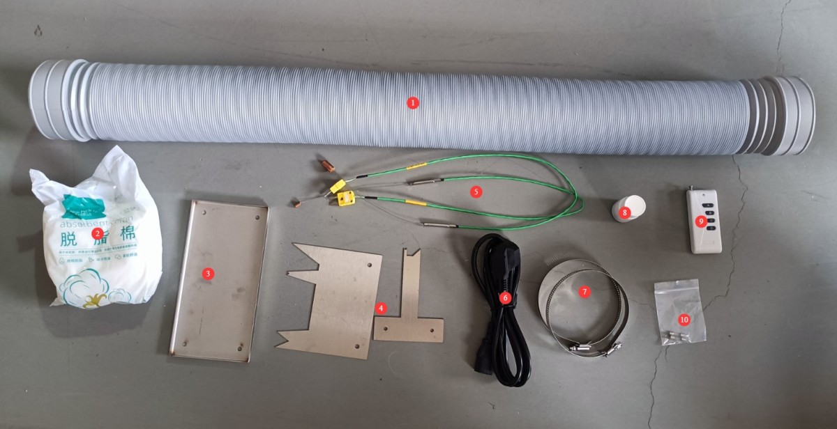
Figure 1
Note: Batteries are classified as hazardous materials and may not be shipped with the product. If you need to use the remote control, please purchase the appropriate batteries for it separately.
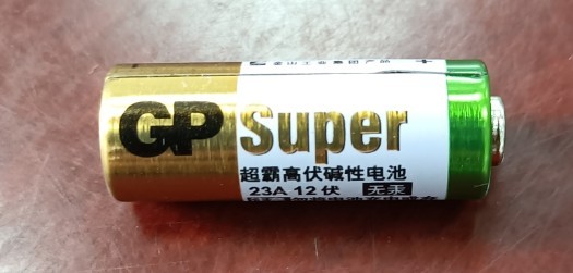
Figure 2
The remote control has the same functions as the touchscreen buttons; users can choose whether or not to use the remote control.
Note: Download links for the electronic user manual, warranty card, and other documents have been sent via email. Please download them as soon as possible. If you missed the email, please feel free to contact us to obtain the download links again.
1.3 Description of Equipment Structure
1.3.1 Front View of the Test Chamber
① Touchscreen; ② Power control, circuit breaker, and power on/off buttons; ③ Gas flow meter and flow adjustment knob; ④ Gas pressure gauge;⑤ Inlet valve (set to the open position at the factory); ⑥ U-tube manometer for monitoring gas backpressure; fill with water containing potassium permanganate (the color of the potassium permanganate facilitates observation of the water level); the liquid level must be ≥200 mm water column; ⑦ Test chamber door;⑧ Two openings to allow the operator to manipulate the Bunsen burner while the test chamber door is closed.
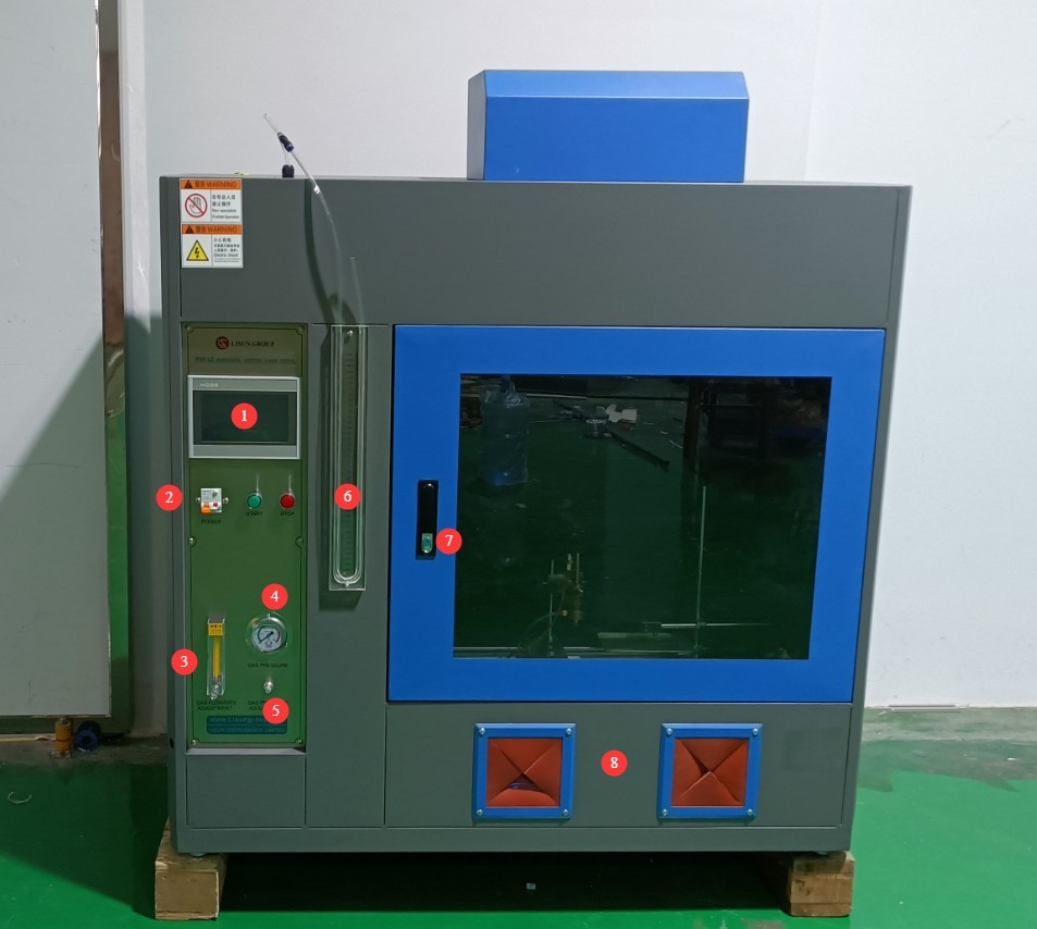
Figure 3
1.3.2 Rear of the Test Chamber
① Exhaust vent, 100 mm in diameter, securely connected to an exhaust duct that extends to the outdoors; ② Air intake; ③ Power cord receptacle.
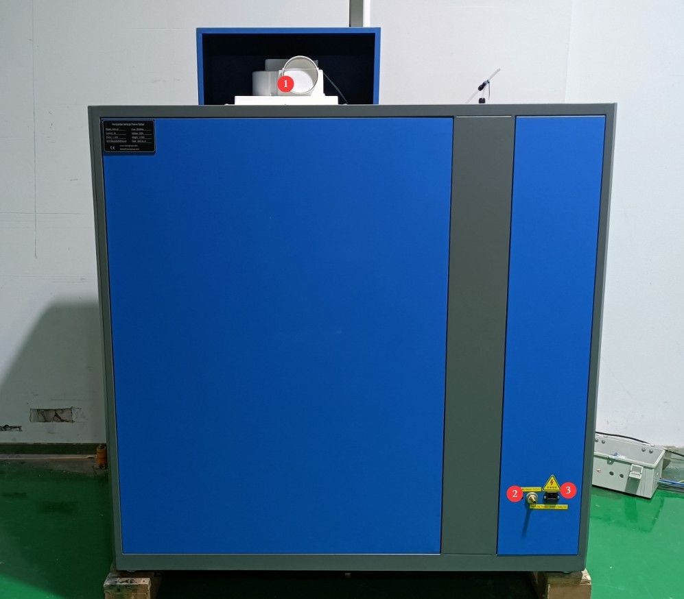
Figure 4
1.3.3 Inside the Test Chamber
① BenSheng lamp, with adjustable height and angle; ② Sample holder, with adjustable height and angle to meet various testing requirements; ③ Omega Type K thermocouple socket.
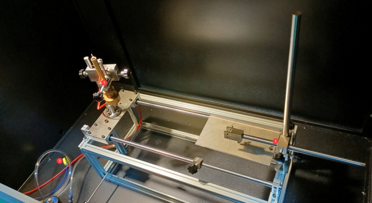
Figure 5
2. Safety Precautions
2.1 Electrical Safety
2.1.1 Power Connection
220V single-phase power; power outlets must comply with safety standards, provide proper grounding, and have a rated current that matches the equipment’s power rating (it is recommended to install a dedicated circuit breaker).
2.1.2 Grounding Specifications
The equipment must be reliably grounded, with a grounding resistance of ≤4 Ω. Gas lines, non-metallic water pipes, or neutral wires must not be used as substitutes for the grounding wire. After grounding is complete, the grounding resistance must be tested using a Grounding Resistance Tester. Power may only be applied after confirming that the resistance meets the requirements, to prevent electric shock, equipment malfunctions, or measurement errors caused by poor grounding.
2.1.3 Contraindications for the Procedure
Before wiring, inspecting, or maintaining the equipment, you must disconnect the main power supply to the equipment and confirm that there is no residual voltage before proceeding;
Do not operate the equipment’s power switch, touchscreen, or instrument buttons with wet hands to avoid the risk of electric shock;
Do not place any foreign objects (such as tools or paper) inside the electrical control cabinet to prevent dust or foreign objects from causing short circuits or damaging components;
Do not plug in or unplug power cords or signal cables while the equipment is running to prevent short circuits that could damage the controller or electrical components.
2.2 Operational Safety
2.2.1 Operational Safety
While the equipment is in operation, non-professionals are prohibited from disassembling or repairing it. In the event of a malfunction, contact after-sales service personnel or operate the equipment under the guidance of a technician;
The High Temperature Chamber door must be closed during testing. Observe the test process through the chamber viewing window to avoid burns from high-temperature radiation or sparks from burning materials;
In the event of a malfunction or abnormality, immediately stop the test and troubleshoot the problem (see “Chapter 9: Troubleshooting and Resolution of Common Problems”). Do not force the equipment to start up; operating the equipment before the problem is resolved may cause further damage to the equipment.
2.2.2 Prohibited Conduct
Do not use propane with a purity of less than 95% or methane with a purity of less than 98%, to avoid compromising flame stability and test accuracy;
Do not open the control cabinet door while the equipment is running to avoid touching internal high-voltage components and causing an electric shock;
Do not disassemble core components without authorization; modifying the equipment will void the warranty and may lead to safety incidents;
Do not place heavy objects (such as tools or accessories) on top of the device to avoid damaging the device panel or impairing heat dissipation;
Do not stack flammable items (such as cardboard boxes, plastic wrap, etc.) around the equipment.
2.3 Environmental Safety
2.3.1 Installation Requirements
The equipment must be installed in an air-conditioned room where the ambient temperature is maintained between 5°C and 25°C and the relative humidity is ≤85%. If the ambient humidity is high, condensation may form near the equipment door and test ports; in such cases, improve room ventilation or use a dehumidifier;
The installation site must be free of high concentrations of dust, corrosive gases (such as sulfur dioxide and chlorine), and flammable or explosive atmospheres. Direct sunlight must not be allowed to shine on the equipment to prevent corrosion of the equipment housing and deterioration of electrical components;
The storage of flammable and explosive materials (such as alcohol, gasoline, etc.) is strictly prohibited in the test area to prevent the risk of fire or explosion;
Propane and methane gases are highly flammable. Store them at a temperature of 40°C or lower, and avoid direct sunlight, violent impacts, or proximity to sources of fire;
The work area is equipped with fire extinguishers (dry chemical or carbon dioxide types), and operators are familiar with how to use them;
Keep the equipment away from locations where ambient temperatures fluctuate significantly, such as near ventilation vents and room entrances, to prevent the device’s temperature control accuracy from being affected;
Stay away from sources of strong magnetic and electric field interference (such as large electric motors and high-voltage equipment).
2.3.2 Space Requirements
The distance between the equipment enclosure and the wall, as well as surrounding structures (such as other test equipment and shelving), must be at least 1000 mm to facilitate maintenance;
At least 2000 mm of space must be left around the equipment door to ensure that the door can be opened in any direction, facilitating the placement and removal of samples.
2.3.3 Horizontal Placement
The device must be placed on a flat surface. Use a level to ensure the device is level: Place the level on the top surface of the device and make sure the bubble is centered. Note: The device has four adjustable feet that can be used to level it. Once leveled, ensure that all four feet are firmly in contact with the floor.
If the equipment is tilted, it will cause the Bunsen burner angle to be inaccurate and may result in the displacement of the sample, the Bunsen burner, the temperature-rising copper block, and other components, thereby affecting the test results.
2.4 Other
For matters not covered in this manual, please proceed with caution or contact us.
3. Introduction to the Touchscreen Program
3.1 User Interface
① Burn time; ② Afterglow time; ③ Afterglow duration; ④ Number of burns; ⑤ PV: current value; ⑥ SV: set value; ⑦ Lighting: turns on the lighting inside the test chamber to facilitate observation; ⑧ Fan: vents smoke generated inside the test chamber after the test is complete;⑨ Ignition; ⑩ Gas On, controls the opening and closing of the gas solenoid valve; ⑪ Start (A), used to initiate the test; ⑫ Afterglow Pause (B), used to record the time it takes for the sample’s afterglow to extinguish;⑬ Afterglow Pause (C), used to record the time it takes for the sample’s afterglow to extinguish;⑭ Reset (D): Press this button after the test is complete or before the next test begins to clear the test data; ⑮ Parameter Settings: Enters the parameter settings interface; ⑯ Test Records: Views historical test data; ⑰ Temperature Calibration: Performs a temperature rise test.
Note: The four buttons (A, B, C, D) can also be controlled using a remote control.
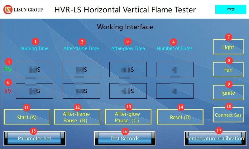
Figure 6
3.2 Parameter Settings Interface
① Ignition time; the default value of 3 seconds is sufficient; ② Interval between two burn cycles during a continuous burn test; ③ Number of burn cycles; ④ Burn duration; ⑤ Afterglow time; ⑥ Afterglow duration.
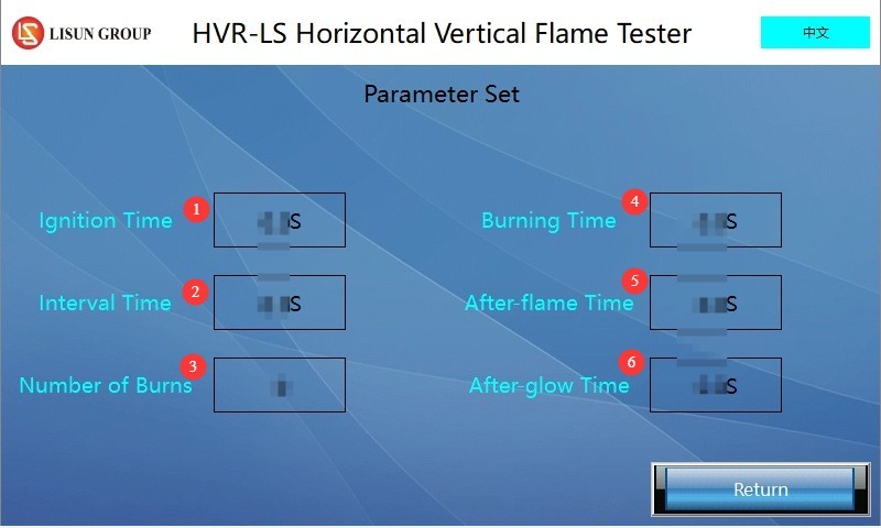
Figure 7
3.3 Test Record Interface
① Residual Flame Duration; ② Residual Glow Duration; ③ Reset: Tap to clear the data on this page.
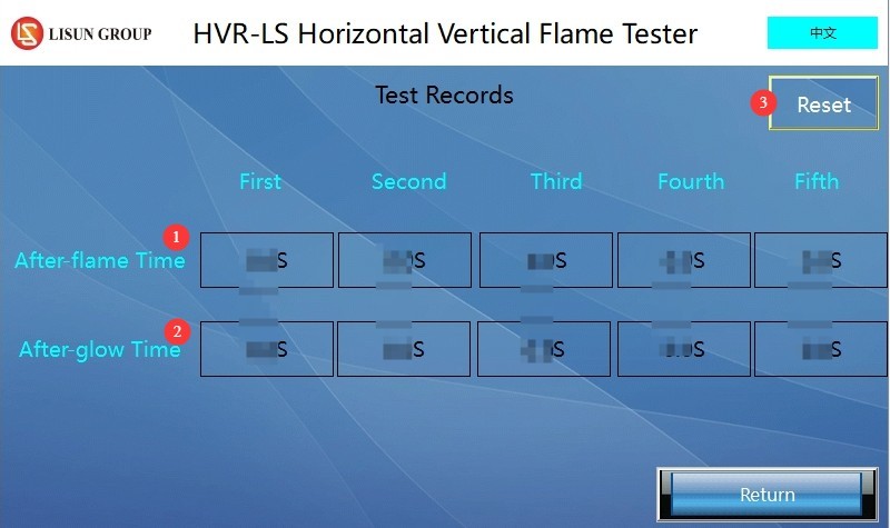
Figure 8
Note: Whether conducting a single-burn test or a continuous-burn test, the afterglow and after-glow-off times for each burn are automatically recorded. The device can record data from up to five burns; once the limit is reached, press the reset button to clear the data before continuing to record.
3.4 Temperature Calibration Interface
① Current temperature display; ② Temperature rise time display; ③ Start temperature setting; ④ End temperature setting; ⑤ Temperature correction (no changes needed); ⑥ Reset: Tap to clear the current data and retest the temperature rise time.
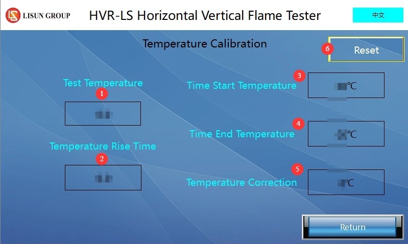
Figure 9
Note: The commonly used standard IEC 60695-11 (GB/T 5169) specifies an initial temperature of 100°C and a final temperature of 700°C for temperature rise testing. Users may also set other initial and final temperatures in accordance with specific standards.
4. Preparations Before the Test
4.1 External Environment
Set the ambient temperature to 23±2°C and the relative humidity to 50±5% to prevent environmental factors from affecting the test results. Note: The temperature and humidity requirements for the equipment’s storage environment differ from those for its operating environment.
4.2 Flame Adjustment
4.2.1 50W Flame Test (Applicable to HB and V Class Tests)
Open the main valve on the gas cylinder and slowly adjust the output pressure of the pressure regulator to 100 kPa (do not allow sudden high pressure);
Adjust the Ben Sheng lamp to a vertical position;
Plug in the device; the touchscreen will display the home screen;
Fine-tune the gas flow knob to ensure it is slightly open, click “Turn on Gas,” then click “Ignition.” If automatic ignition fails, adjust the position of the ignition needle (maintaining a distance of about 10 mm from the burner nozzle), or use a manual ignition torch to ignite the flame. Special Note: Minimize the time interval between pressing “Turn on Gas” and successful ignition (less than 5 seconds) to prevent gas buildup inside the chamber;
Continue adjusting the flow control knob until the flow rate reaches 105 ml/min;
Adjust the pressure regulator at the base of the Bunsen burner so that the back pressure in the U-tube manometer reaches 10 mm water column (this must be adjusted in conjunction with the gas flow rate, as the two factors influence each other);
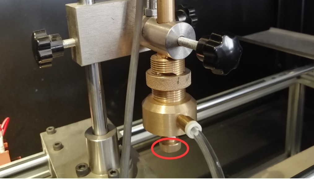
Figure 10
Adjust the air control device to change the size of the outer flame;
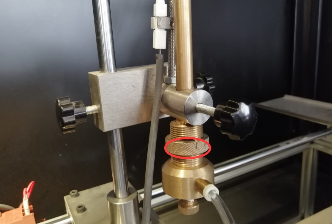
Figure 11
Use a stainless steel gauge to measure the flame height, ensuring that the flame is a blue flame of 20 ± 1 mm (with no yellow flame).
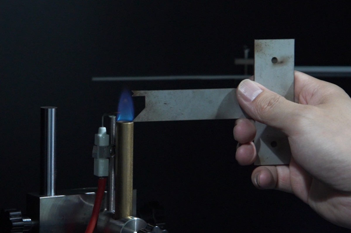
Figure 12
Once the flame has been adjusted properly, click “Gas On” again to shut off the gas supply and extinguish the flame. For safety, turn the gas valve on the front panel of the equipment clockwise to the closed position.
If temperature calibration or combustion testing is performed later, simply reopen the intake valve, ignite the system, and proceed with the test; no further debugging is required.
4.2.2 500W Flame Test (Applicable to 5V-Level Testing)
Open the main valve on the gas cylinder and slowly adjust the output pressure of the pressure-reducing valve to 100 kPa (do not apply high pressure suddenly);
Adjust the Ben Sheng lamp to a vertical position;
Plug in the device; the touchscreen will display the home screen;
Fine-tune the gas flow knob to ensure it is slightly open, click “Turn on Gas,” then click “Ignition.” If automatic ignition fails, adjust the position of the ignition needle (maintaining a distance of about 10 mm from the burner nozzle), or use a manual ignition torch to ignite the flame. Special Note: Minimize the time interval between pressing “Turn on Gas” and successful ignition (less than 5 seconds) to prevent gas buildup inside the chamber;
Continue adjusting the flow control knob to 965 ml/min;
Adjust the pressure control valve at the base of the Bunsen burner so that the back pressure in the U-tube manometer reaches 125 ± 25 mm water column (this must be adjusted in conjunction with the gas flow rate, as the two factors influence each other);
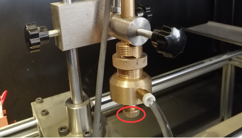
Figure 10
Adjust the air control device to change the size of the outer flame;
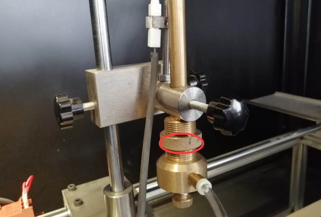
Figure 11
Measure the flame height using a stainless steel gauge so that the total flame height is 125 ± 10 mm, the inner flame height is 40 ± 2 mm, and the flame is blue;
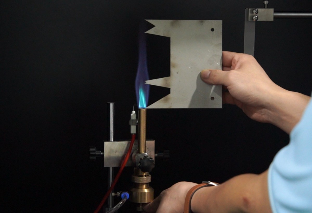
Figure 13
Once the flame is properly adjusted, click “Turn On Gas” again to shut off the gas supply and extinguish the flame. For safety, turn the gas valve clockwise to the closed position.
If temperature calibration or combustion testing is performed later, simply reopen the intake valve, ignite the system, and conduct the test; no further debugging is required.
4.3 Sample Pretreatment and Sample Mounting
4.3.1 Sample Pretreatment
General Pretreatment: Samples must be left in an environment at 23±2°C and 50±5% RH for at least 48 hours.
Sample Cleaning: Wipe the sample surface with lint-free cotton to remove oil and dust, ensuring the surface is clean and free of contaminants.
Sample Marking: Mark the sample number, thickness, and test rating (e.g., HB, V-0) on a non-burned area of the sample.
4.3.2 Sample Installation
4.3.2.1 HB Class (Horizontal Burning)
Sample Requirements: 125 ± 5 mm long × 13.0 ± 0.5 mm wide; a sample with the minimum thickness plus a 3 ± 0.2 mm sample (if the minimum thickness is greater than or less than 3 mm, the 3 mm sample is not required); 3 pieces per set, for a total of 2 sets.
Clamping method: Clamp the tail end of the specimen near the 100 mm mark, with the specimen oriented horizontally along its length and at an angle of 45±2° to the horizontal plane along its width.
Additional Setup: Secure a metal mesh 100 ± 1 mm below the sample.
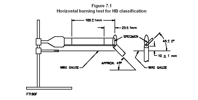
Figure 14
4.3.2.2 Class V (V-0/V-1/V-2, Vertical Burning)
Sample Requirements: 125 ± 5 mm long × 13.0 ± 0.5 mm wide; samples representing the minimum and maximum thicknesses (add a sample with an intermediate thickness if the results are inconsistent), 5 pieces per set, for a total of 2 sets.
Clamping method: Clamp 6 mm from the top of the sample, with the clamping direction perpendicular to the length of the sample; the bottom of the sample should be 300 ± 10 mm from the top surface of the cotton layer.
Additional Setup: Place 0.08 g of 50 mm × 50 mm pure cotton (maximum thickness ≤ 6 mm) directly beneath the sample.
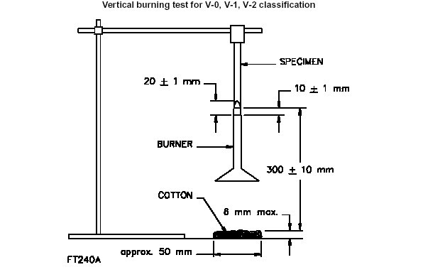
Figure 15
4.3.2.3 5V Class (5VA/5VB, 500W vertical combustion)
Sample Requirements: Strip samples should measure 125 ± 5 mm in length by 13.0 ± 0.5 mm in width; block samples should measure 150 ± 5 mm by 150 ± 5 mm. Samples with the minimum thickness must be provided. Each set should consist of 5 pieces (strip samples) and 3 pieces (block samples), for a total of 2 sets.
Clamping method: Bar-shaped samples are clamped vertically (with the upper end clamped 6 mm from the top); block-shaped samples are clamped horizontally; the lower end of the sample is 300 ± 10 mm from the cotton layer.
Supplementary Settings: Same as the placement requirements for Class V cotton; when testing block samples, apply the flame to the center of the bottom surface.
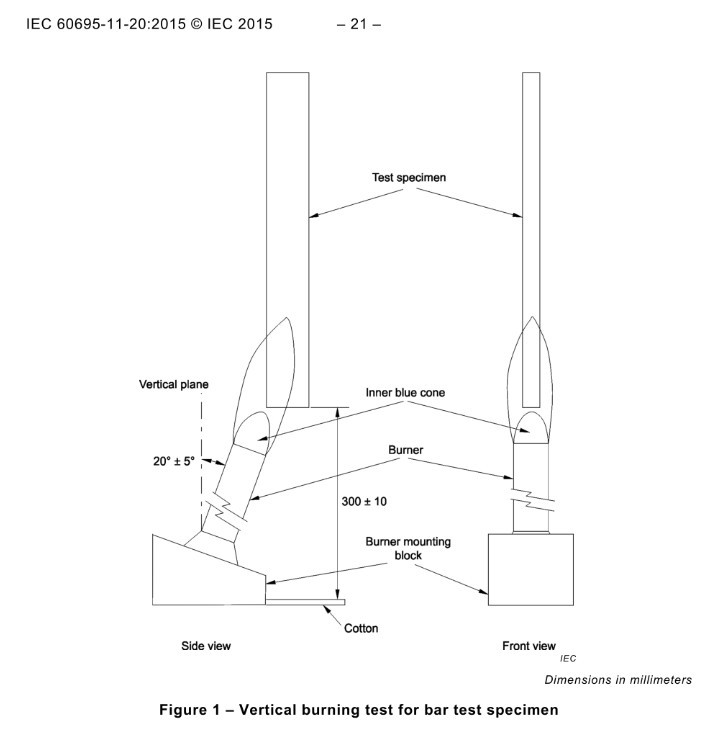
Figure 16
4.3.2.4 Installation Notes
The sample must be securely clamped with no looseness to prevent it from shifting during combustion.
Adjust the position of the sample holder and the Bunsen burner to ensure that the flame’s point of contact meets the standard (e.g., the center of a Class V flame is aligned with the midpoint of the sample’s lower edge).
5. Operating Procedures for Horizontal and Vertical Combustion Tests
5.1 Test Parameter Settings
Go to the “Parameter Settings” screen on the touchscreen and configure the parameters as shown in the table below.
| Test Level | Ignition Timing | Burn Time | Interval | Number of Consecutive Burn Cycles | Flame Power | Other Parameters |
| HB Grade | 3S | 30±1S | 0S | 1 time | 50W | Burning angle: 45°, flame height: 20±1 mm |
| V-0/V-1/V-2 | 10 ± 0.5 s | 2 times (with an interval of ≤5 seconds) | Burning angle: 0°, flame height: 20 ± 1 mm | |||
| 5VA/5VB | 5 ± 0.5 S | 5 times | 500W | Burning angle: 20±5°, flame height: 125±10 mm | ||
5.2 Test Procedure (General Procedure + Specific Requirements by Level)
5.2.1 General Process
Confirm that preparations are complete: the flame test has passed, the sample is installed correctly, and there are no gas leaks;
Close the test chamber door, fully open the air intake valve on the front panel of the unit, and tap “Start” on the touchscreen; the unit will automatically perform the sequence “Gas Activation → Ignition → Combustion Timer”;
Once the burn time has elapsed, the unit automatically shuts off the gas supply, and the after-flame timer automatically starts;
Observe the afterglow of the sample. When the afterglow goes out, immediately click “Afterglow Pause” and record the afterglow duration. If the afterglow ignites the cotton, record this phenomenon;
After the afterglow timer stops, the afterglow duration timer automatically starts; when the afterglow goes out, tap “Pause Afterglow” to record the afterglow duration;
If this is a single combustion test, the test is complete. If this is a series of combustion tests, the Bunsen burner will automatically reignite at the end of the interval to begin the next combustion test; for each combustion test, record the afterglow time, afterburn time, and other observations using the same method.
Replace the sample with the next one and repeat the steps above until you have completed testing a set of samples.
Note: If a sample is irregular in shape and deforms or twists during combustion, a tracking test must be performed in accordance with the standard; that is, the Bunsen burner must be moved as needed to ensure that the deformed sample remains within the test area. When conducting this test, the Bunsen burner must be removed, and the tester must hold it by hand while wearing heat-resistant gloves.
5.2.2 Tiered Special Processes
5.2.2.1 HB-Level Test
Tilt the Bunsen burner at a 45° angle, position the flame 6 mm deep into the sample, and allow it to burn for 30 ± 1 seconds or until it reaches the 25 mm mark, at which point it should be removed.
Start timing when the flame reaches the 25±1 mm mark, and record the time it takes for the flame to reach the 100±1 mm mark (or the time when the flame stops burning).
Calculate the combustion velocity: V = 60L/t (where L is the combustion length in mm and t is the combustion time in s).
5.2.2.2 Class V Test
After the first combustion has continued for 10 ± 0.5 seconds, remove the Bunsen burner and record the afterglow time t1.
After the afterglow has extinguished, immediately relight the Bunsen burner; after it has burned for 10 ± 0.5 seconds, remove it, and record the afterglow time t2 and the afterglow duration t3.
If molten material drips from the sample during combustion, tilt the Bunsen burner at a 45° angle to prevent the drips from clogging the burner nozzle.
If the flame is extinguished by the sample gas, immediately reignite it to ensure that the total combustion time reaches 10 ± 0.5 seconds.
5.2.2.3 5V-Level Test
The Bunsen burner is tilted at an angle of 20±5°, with the inner flame touching the tip (for strip-shaped samples) or the center of the bottom surface (for block-shaped samples).
After burning for 5 ± 0.5 seconds, remove the sample; repeat the burning process 5 times at 5 ± 0.5-second intervals.
After each combustion, observe the condition of the sample and record the afterglow/afterburn time; for block-shaped samples, check whether they have been burned through.
5.2.2.4 Requirements for Test Records
Record, in order by sample number, the afterglow time, afterburn time, burn length (HB class), whether the cotton was ignited, whether it burned through (5V class), and whether it burned completely.
If a sample fails to meet the requirements, a second set of samples may be used for retesting (up to one nonconforming item per group for Grade HB, and up to one nonconforming item per group for Grade V and 5V).
6. Post-Test Procedures
6.1 Equipment Operation After Testing
6.1.1 Safe Handling
Tap “Fan” on the touchscreen and let it run for 5 minutes to clear any residual smoke from the cabinet.
Turn off the device’s power switch and circuit breaker.
If molten material drips during the test, wait until the equipment has cooled (≥30 minutes) before cleaning it.
6.1.2 Equipment Cleaning
Wipe the interior of the test chamber with a dry cloth to remove soot and drips (do not rinse with water).
Clean the sample holder and the Bunsen burner surface to remove any residual impurities and ensure that moving parts operate smoothly.
Wipe the transparent viewing window to remove stains and ensure a clear view.
6.2 Sample Preparation
Samples from the test (including unburned material and combustion residues) must be sorted and collected, then placed in heat-resistant containers.
If samples contain flammable residues or toxic substances, they must be disposed of in an environmentally safe manner in accordance with environmental protection requirements; arbitrary disposal is prohibited.
Retain a representative selection of samples (such as conforming and nonconforming samples) for subsequent re-inspection or traceability.
6.3 Equipment Storage
6.3.1 Short-Term Storage Requirements
If the equipment is for everyday use, no special handling is required.
6.3.2 Long-Term Storage Requirements
If the device will not be used for an extended period (more than one month), please unplug the power cord, drain the potassium permanganate solution from the U-tube manometer, clean it, and refill it before the next use.
Cover the equipment with a dust cover to prevent dust buildup.
The device should be powered on once a month for half an hour to prevent the aging of electrical components (such as capacitors and contactors).
7. Temperature Calibration
7.1 Calibration Preparation
7.1.1 Calibration Conditions
Environmental conditions: Temperature 23±2°C, humidity 45%–75%, no airflow disturbances.
Equipment: Thermocouple and 50W copper block for measuring flame-induced temperature rise—both are original equipment.
7.1.2 Basis for Calibration
IEC 60695-11 (GB/T 5169) calibration parameter: 50 W flame temperature rise time (the time it takes for a copper block to rise from 100 °C to 700 °C). The standard value is 44 ± 2 s.
7.2 Procedure
Adjust the 50W flame as described in Section 4.2.1, and then extinguish the flame.
Plug the thermocouple connector into the Omega Type K thermocouple socket provided inside the test chamber:
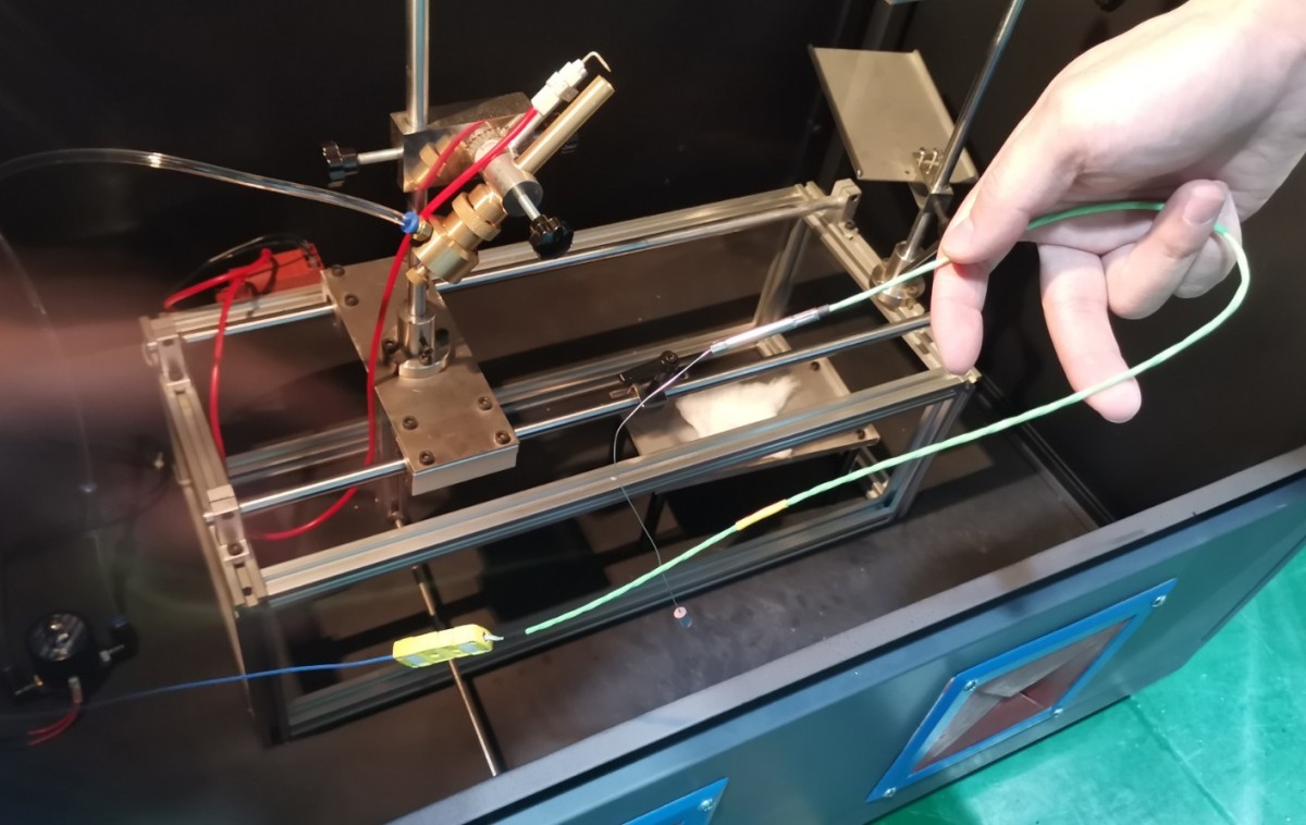
Figure 17
Secure the standard copper block 10 mm directly above the Bunsen burner, ensuring that the flame fully impinges on the copper block.
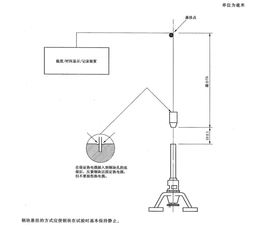
Figure 18
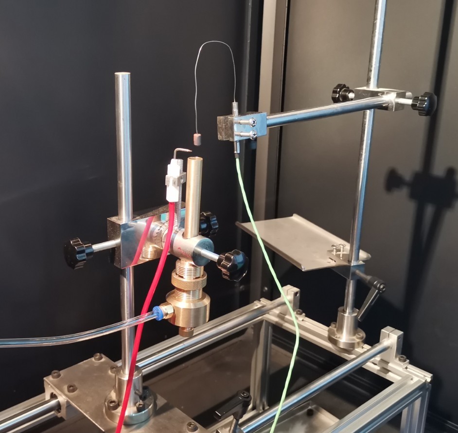
Figure 19
Go to the temperature calibration screen and verify that the “Start Temperature” is set to 100°C and the “End Temperature” is set to 700°C.
Go to the operating screen, click “Turn on Gas” and “Ignition” to start the flame.
Once the temperature of the copper block reaches 100°C, the “temperature rise time” begins counting automatically. When the temperature of the copper block reaches 700°C, the “temperature rise time” stops counting automatically. Remove the Bunsen burner or shut off the gas supply.
Repeat Calibration: Allow at least 30 minutes between each calibration (until the copper block has cooled to room temperature). Perform a total of three calibrations and use the average value as the final temperature rise time.
7.3 Handling Temperature Deviations in Calibration
7.3.1 The temperature rise time complies with the requirements of the standard
If the temperature rise time is between 42 and 46 seconds (standard range), the calibration is considered acceptable and no adjustment is necessary.
7.3.2 If the temperature rise time is <42S (flame is too intense)
Slightly reduce the gas flow rate (≤5 ml/min) or lower the backpressure (≤1 mm water column).
Readjust the flame and repeat the calibration steps until the temperature rise time meets the standard.
7.3.3 If the temperature rise time is greater than 46 seconds (the flame is too weak)
Slightly increase the gas flow rate (≤5 ml/min) or increase the backpressure (≤1 mm water column).
Check whether the Bunsen burner is clogged and whether the ignition needle is positioned correctly; recalibrate after troubleshooting.
7.3.4 Note
If the device still does not meet the standards after adjustment, the thermocouple or copper block may be damaged; in this case, replace them with genuine parts and recalibrate the device.
The temperature rise time is used to determine whether the gas you are using, the flame you are calibrating, and the test conditions meet the standard test requirements. If the temperature rise time is incorrect, it means your test does not meet the standard requirements; it does not mean there is a problem with the equipment itself.
Routine Maintenance
| Maintenance Cycle | Maintenance Projects | Maintenance Operations |
| After each test | Equipment Cleaning | 1. Wipe down the interior and exterior of the test chamber, the observation window, and the fixtures; 2. Clean up any drippings and soot from the drip tray |
| Once a week | Bearing Maintenance | Wipe down the linear bearing rail with a cloth dampened with vegetable oil to ensure the moving parts operate smoothly. |
| Once a month | Gas System Inspection | 1. Check the gas connection for leaks (using soapy water); 2. Inspect the hoses for signs of aging and replace them if necessary; 3. Clean the flow meter and differential pressure gauge |
| Once every 3 months | Flame Calibration | Conduct a 50W flame temperature rise test to verify whether the temperature rise time meets the requirement of 44±2 seconds. |
| Once every 6 months | Electrical System Inspection | 1. Check that the power lines and ground terminals are secure; 2. Replace any worn-out fuses; 3. Test the ignition system’s performance |
| Once a year | Comprehensive Maintenance | 1. Replace the gas hoses and gaskets; 2. Calibrate the touchscreen’s timing accuracy; 3. Inspect the Bunsen burner for wear and replace it if necessary; 4. Contact the supplier to arrange for professional testing and calibration |
9. Troubleshooting and Resolving Common Problems
9.1 Common Problems and Troubleshooting Steps
| Fault Symptoms | Possible Causes | Remedial Measures |
| The igniter is not producing a high-voltage spark | 1. Poor contact between the high-voltage lead and the spark plug; 2. Damaged spark plug; 3. Power supply not grounded or voltage instability; 4. Ignition module malfunction | 1. Inspect the high-voltage leads, unplug and reinsert them, and secure them; 2. Replace the ignition needle (original equipment); 3. Verify that the power supply is grounded, and check the voltage with a multimeter; 4. Contact the supplier to repair or replace the ignition module |
| The high-voltage spark is present, but ignition fails. | 1. The gas flow is not turned on or is too low; 2. There is a leak at the gas connection, and no gas is flowing through the line; 3. The distance between the ignition needle and the burner nozzle is incorrect (too far/too close); 4. There is residual air in the line; 5. The ambient temperature is too low (<10°C) | 1. Adjust the flow meter to ensure the flow rate is ≥105 ml/min (50 W); 2. Check the connections with soapy water, tighten any loose parts, and replace any damaged hoses;3. Adjust the spark plug gap to approximately 10 mm; 4. Turn on the “Gas Supply” for 5–10 seconds, then turn it off; repeat 2–3 times to purge air; 5. Raise the ambient temperature, or use a manual ignition torch to ignite the flame |
| The flame is unstable (fluctuating in size/yellowish) | 1. Insufficient gas purity; 2. Flow rate and back pressure were not adjusted in coordination; 3. The air regulation device was not properly adjusted; 4. The Bunsen burner is clogged | 1. Replace the methane gas with a purity of ≥99.9%; 2. Readjust the flow rate and back pressure differential (50W: 105 ml/min + 10 mm; 500W: 965 ml/min + 125 mm);3. Adjust the air regulator so that the flame turns blue; 4. Purge the Bunsen burner nozzle with compressed air (oil-free) to remove any blockages |
| The temperature rise time does not meet the standard (>46S/<42S) | 1. Improper flame parameter settings; 2. Poor contact between the thermocouple and the copper block; 3. Oxidation layer on the surface of the copper block; 4. Unstable gas pressure | 1. Adjust the flame flow rate and backpressure differential as described in Section 4.2.1; 2. Reinstall the thermocouple, ensuring it makes tight contact with the copper block; 3. Sand the oxide layer off the surface of the copper block; 4. Check the gas cylinder pressure regulator to ensure the pressure remains stable at 100 kPa. |
| Touchscreen Not Responding/Display Issues | 1. The power is not connected or the voltage is too low; 2. The touchscreen ribbon cable is loose; 3. The touchscreen is damaged; 4. The device software has malfunctioned | 1. Check the power connection and replace the power outlet; 2. After turning off the power, open the device panel and unplug and replug the touchscreen ribbon cable (to be performed by a qualified technician); 3. Contact the supplier to replace the touchscreen; 4. Restart the device; if the problem persists, restore the factory settings (be sure to back up the parameters first). |
| Gas Leak (Drop in liquid level in U-tube differential pressure gauge / Smell of gas) | 1. Insufficient liquid level in the U-tube; 2. Aging gas connection gasket; 3. Pipe damage; 4. Malfunctioning pressure regulating valve | 1. Top off the water containing potassium permanganate to a level of ≥200 mm; 2. Replace the joint gasket (original equipment); 3. Inspect the piping and replace any damaged sections; 4. Close the cylinder valve and contact the supplier to repair the regulating valve. |
| Test data cannot be recorded or saved | 1. History data was not cleared by clicking “Reset”; 2. Incorrect parameter settings (e.g., number of burn cycles set to 0); 3. Touchscreen storage malfunction; 4. Incorrect operating procedure (failure to press “Afterglow Pause” or “Afterburn Pause”) | 1. Click “Reset” before each test; 2. Reset the parameters and ensure the number of cycles is ≥1; 3. Restart the device; if the settings still cannot be saved, contact maintenance; 4. Follow the procedure in Section 5.2 to ensure data is recorded promptly. |