English
 中文简体
中文简体 English
 Русский
 Español
 Português
 Türkçe
 العربية
 Deutsch
 Polski
 Italiano
 Français
 한국어
한국어 ไทย
ไทย Tiếng Việt
 日本語
日本語





























High And Low Temperature Thermal Shock Chamber
User's Manual
Applicable LISUN models: HLST-100D-A、HLST-100D-B、HLST-100D-C、HLST-250D-A、HLST-250D-B、HLST-250D-C、HLST-500D、HLST-500D-A、HLST-500D-B、HLST-500D-C
1. Basic Understanding of Equipment
1.1 Key Technical Specifications
| LISUN Model | HLST-100D-* | HLST-250D-* | HLST-500D-* | |
| Enclosure Structure (Box Type) | Two-compartment | |||
| Chamber Dimensions (mm) | 450 × 450 × 500 | 600×600×600 | 800×800×800 | |
| Basket Dimensions (Two-Bin Model) | 250 × 250 × 250 | 400 × 400 × 450 | 600×600×600 | |
| Sample Holder (Standard) | First Floor | |||
| Temperature, Power, and Cooling Method Ranges | Temperature Range | A: -20°C to 150°C | ||
| Power | Approximately 15 kW | Approximately 25 kW | Approximately 38 kW | |
| Cooling Method | Air-cooled | |||
| Temperature Range | B: -40°C to 150°C | |||
| Power | Approximately 22 kW | Approximately 32 kW | Approximately 45 kW | |
| Cooling Method | Air-cooled | |||
| Temperature Range | C: -50°C to 150°C | |||
| Power | Approximately 32 kW | Approximately 43 kW | Approximately 48 kW | |
| Cooling Method | Air-cooled | Water-cooled | ||
1.2 Unboxing and Checking the Accessories
1.2.1 Unpacking and Visual Inspection
When unpacking the equipment, handle it gently to avoid scratching the exterior casing with sharp tools. After unpacking, first inspect the exterior of the main unit to ensure there is no visible deformation, dents, or peeling paint, and that the panel instruments and buttons are not damaged or loose. If you discover any damage or deformation to the device or its accessories, do not power it on. Contact LISUN customer service immediately.
1.2.2 Host-type
1 main unit of a High and Low Temperature Chamber:
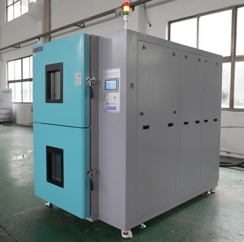
Figure 1
Water-cooled unit (for the equipment cooling system; must be compatible with the host machine’s water-cooled condenser. Note: If the equipment is air-cooled, please disregard the section on the water-cooled unit in the manual) 1 unit:
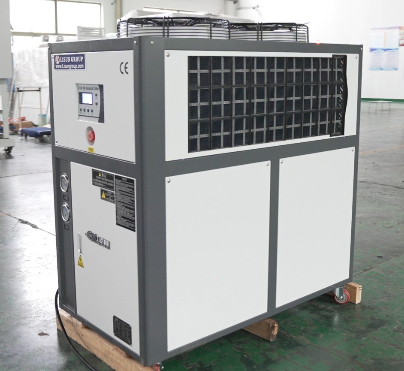
Figure 2
1.2.3 Consumables and Accessories
Open the accessory box. Standard accessories include: a spare solid-state relay, rubber plugs, spare fuses, and a triangular key.
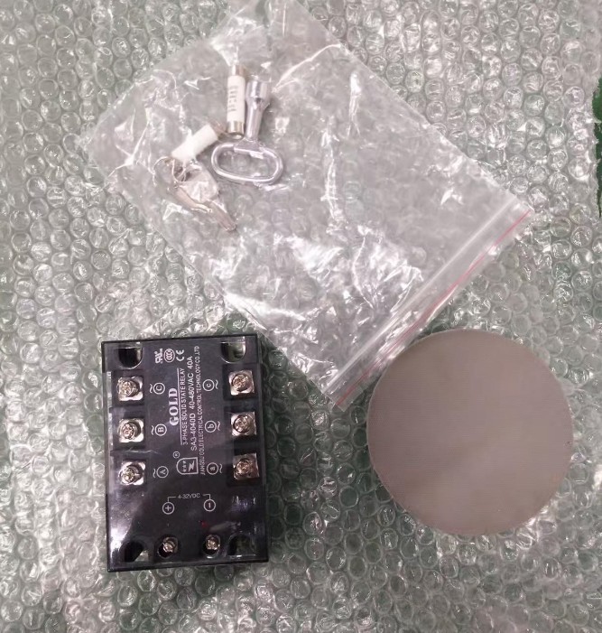
Figure 3
Download links for the digital user manual, warranty card, and other documents have been sent to you via email. Please download them as soon as possible. If you missed the email, please feel free to contact us to request a new download link.
1.3 Description of Equipment Structure
1.3.1 Front View of the Test Chamber
① Three-color indicator light showing the equipment’s operating status; ② High-temperature chamber; ③ Low-temperature chamber; ④ Sample basket (which moves back and forth between the high-temperature and low-temperature chambers at set intervals during operation); ⑤ Control panel.
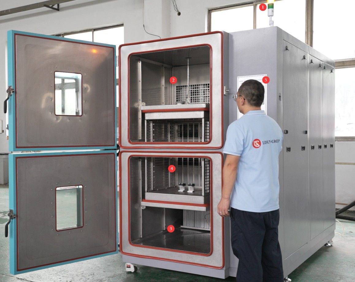
Figure 4
1.3.2 Rear of the Test Chamber
① Power cord; ② Compressed air connection (customers must provide their own air compressor to control the lifting of the basket); ③④ Outlet and inlet ports for connecting to the chiller (connection instructions will be provided later).
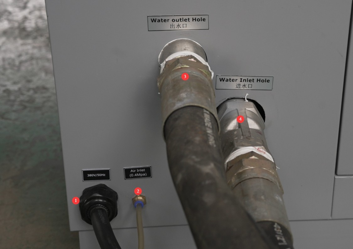
Figure 5
There are three overflow outlets; simply connect them to the drain with a hose.
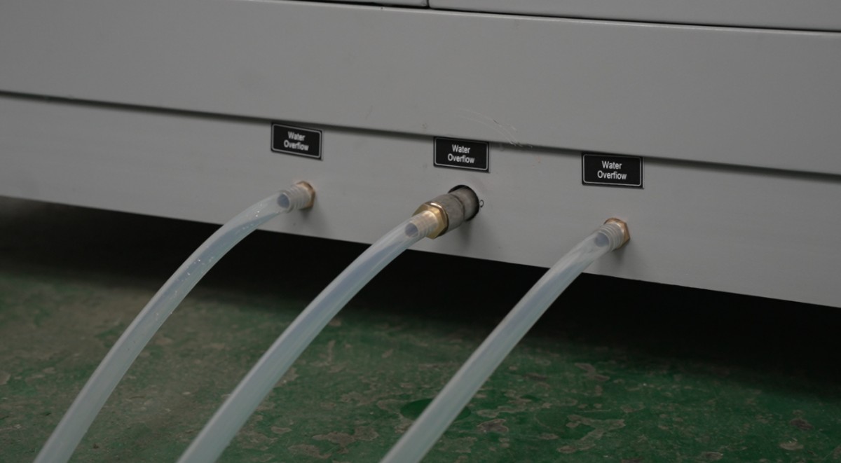
Figure 6
2. Safety Precautions
2.1 Electrical Safety
2.1.1 Power Connection
The equipment must be powered by a dedicated circuit with a three-phase, five-wire system rated at AC 380 V, 50 Hz (or 60 Hz, optional). Multiple units must not share a single power source to prevent voltage drops that could cause abnormal performance or equipment failure. Before connecting the power supply, ensure the power is turned off. When wiring, strictly distinguish between the live wires (L1, L2, L3), neutral wire (N), and ground wire (PE). The wiring sequence must comply with the requirements of the equipment’s electrical schematic; reversing the live and neutral wires is strictly prohibited.
The equipment is equipped with a phase sequence protector. After wiring, check the phase sequence before powering on: If the green “Un” light and the yellow “R” light on the phase sequence protector are both lit, the wiring is correct; If only one of the lights is on or none are lit, this indicates reverse phase. Turn off the main power supply, swap the positions of the two adjacent live wires (L1 and L2), and then check again;
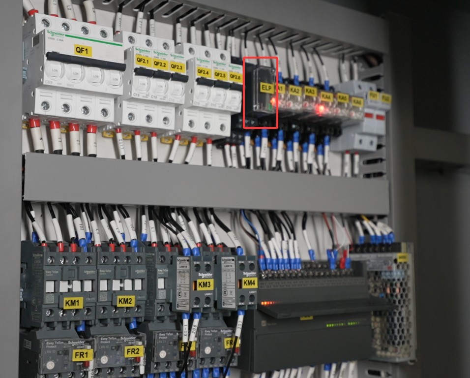
Figure 7
After completing the wiring, pull firmly on the terminal blocks to ensure the connections are secure and there is no looseness.
2.1.2 Grounding Specifications
The equipment must be reliably grounded, with a grounding resistance of ≤50 Ω. Gas pipes, non-metallic water pipes, or neutral wires must not be used as substitutes for the grounding wire. After grounding is complete, the grounding resistance must be tested using a Grounding Resistance Tester. Power may only be applied after confirming that the requirements are met to prevent electric shock, equipment malfunctions, or measurement errors caused by poor grounding.
2.1.3 Contraindications for the Procedure
Before wiring, inspecting, or maintaining the equipment, you must turn off the circuit breaker on the back of the equipment and disconnect the main power supply. Verify that there is no residual voltage before proceeding;
Do not operate the equipment’s power switch, touchscreen, or instrument buttons with wet hands to avoid the risk of electric shock;
Do not place any foreign objects (such as tools or paper) inside the electrical control cabinet to prevent short circuits or component damage caused by dust or foreign objects;
Do not plug in or unplug power cords or signal cables while the equipment is running to prevent short circuits that could damage the controller or electrical components.
2.2 Operational Safety
2.2.1 Test Specimen Requirements
The equipment must not be used for testing flammable, explosive, toxic, or highly corrosive substances (such as alcohol, gasoline, strong acids, and strong bases). The equipment is not equipped with explosion-proof devices, and such substances may cause fires, explosions, or corrosion of the equipment;
If the test specimen generates heat (such as during power-on testing of electronic components), an external, independent power source must be provided for the specimen. Do not use the device’s own power supply directly to avoid overloading the device’s circuitry;
The sample volume must not exceed 80% of the basket’s capacity, and the weight must not exceed the equipment’s specified load capacity (HLST-500D basket load capacity ≤ 20 kg) to prevent basket deformation or failure of the lifting mechanism.
2.2.2 Operational Safety
While the equipment is in operation, non-professionals are prohibited from disassembling or repairing it. In the event of a malfunction, contact after-sales service personnel or operate the equipment under the guidance of a technician;
Avoid opening the chamber door as much as possible during the test. Opening the door when the temperature is high (≥80°C) or low (≤-20°C) may cause burns or frostbite to the operator and may disrupt the temperature equilibrium inside the chamber, thereby affecting the test results; If it is necessary to open the chamber door, wear heat-resistant gloves and safety goggles, open the door slowly, and wait until the temperature inside the chamber has stabilized before proceeding;
Do not set the temperature above the range specified for the equipment; exceeding the temperature limit may cause the heating element to burn out, damage the refrigeration system, or even result in a fire;
When placing samples, distribute them evenly throughout the basket. Do not overcrowd it; leave at least one-third of the space empty to ensure proper circulation of hot air inside the chamber and prevent localized temperature variations;
If the equipment triggers an alarm (red light on the three-color indicator + audible alarm), immediately stop the test and troubleshoot the fault (see “Chapter 7: Troubleshooting and Resolution of Common Faults”). Do not force the equipment to start; operating the equipment before the fault is resolved may cause further damage.
2.2.3 Prohibited Conduct
Do not open the control cabinet door while the equipment is running to avoid electric shock from coming into contact with high-voltage components inside;
Do not disassemble core components such as the temperature sensor (Type T), heating element, or condenser without authorization. Modifying the equipment will void the warranty and may result in safety incidents;
Do not place heavy objects (such as tools, accessories, etc.) on top of the device to avoid damaging the device panel or impeding heat dissipation;
Do not stack flammable items (such as cardboard boxes, plastic wrap, etc.) around the equipment; keep the equipment’s ventilation openings clear to prevent the risk of fire;
2.3 Environmental Safety
2.3.1 Installation Requirements
The equipment must be installed in an air-conditioned room where the ambient temperature is maintained between 5°C and 25°C and the relative humidity is ≤85%. If the ambient humidity is high, condensation may form near the equipment door and test ports; in such cases, improve room ventilation or use a dehumidifier;
The installation site must be free of high concentrations of dust, corrosive gases (such as sulfur dioxide and chlorine), and flammable or explosive atmospheres. Direct sunlight must not be allowed to shine on the equipment to prevent corrosion of the equipment housing and deterioration of electrical components;
Keep the device away from areas with significant fluctuations in ambient temperature, such as near vents or indoor entrances, to prevent the device’s temperature control accuracy from being affected.
2.3.2 Space Requirements
The distance between the equipment enclosure and the wall, as well as surrounding structures (such as other test equipment and shelving), must be at least 1500 mm to ensure unobstructed ventilation at the equipment’s heat vents (on the back and sides);
At least 2000 mm of space must be left at the equipment door to ensure the door can be opened in any direction, facilitating the placement and removal of samples;
The water-cooled unit should be installed close to the main unit, and the length of the water-cooling tubing should be kept within 5 meters to prevent a decrease in cooling efficiency caused by excessively long tubing.
2.3.3 Horizontal Placement
The equipment must be placed on a level surface. Use a spirit level to ensure the equipment is level: Place the spirit level on the top surface of the equipment and confirm that the bubble is centered. Note: The following types of legs are adjustable to ensure the test chamber is level:
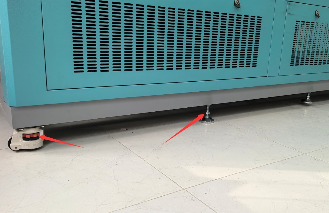
Figure 7.1
If the equipment is tilted, it may cause the basket lifting mechanism to jam, result in uneven temperature distribution inside the chamber, or even lead to poor door sealing, which can affect test results and equipment lifespan.
2.4 Other
For matters not covered in this manual, please proceed with caution or contact us.
3. Preparations Before the Test
3.1 Connecting the Water-Cooled Unit
3.1.1 Water Pipe Connections
Ensure that both the water-cooling unit and the shock chamber main unit are powered off, then remove the included water-cooling tubing and clamps;
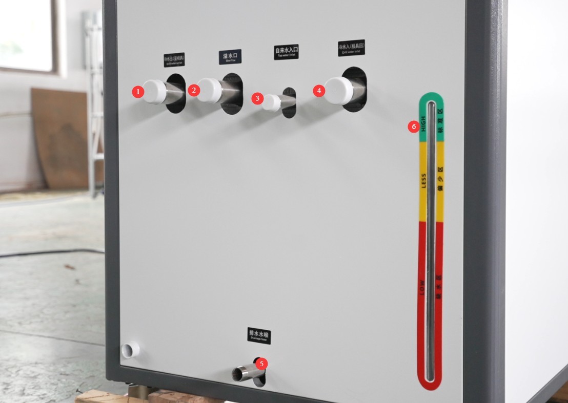
Figure 8
On the back of the water chiller: ① Cold water outlet—connect to the “inlet” of the shock tank; ② Overflow outlet—simply connect to the drain; ③ Tap water inlet—connect to the tap water supply; keep the tap water valve open at all times to supply water to the chiller;④ Chilled water inlet—connect to the surge tank’s “outlet”; ⑤ Drain outlet—use for draining; connect to the drain; ⑥ Water level indicator—the level must reach the green zone. Ensure connections are correct; do not reverse them. For the surge tank’s “outlet” and “inlet,” refer to Section 1.3;
Place 2 clamps on each connection point (one on top and one on bottom), and use a screwdriver to tighten the clamp bolts until the water-cooling tubing is secure and does not move when pulled firmly;
Once the connection is complete, apply a small amount of soapy water to the joint, turn on the water-cooling unit (with water flowing but the power off), and check for bubbles at the joint. If bubbles appear, retighten the clamp until there are no leaks.
3.1.2 Connect the Power Supply and Turn On the Unit
The water-cooled unit’s power supply specifications are AC 380 V, 50 Hz (the same as the main unit). It must be connected to a dedicated circuit, and when wiring, distinguish between the live, neutral, and ground wires to ensure a reliable ground connection;
After connecting the power, press the power button on the water-cooled unit and check its operating status: the fan is rotating normally, the water pump is not making any unusual noises, and the pressure gauge shows a pressure between 0.2 and 0.5 MPa (within the normal range);
Allow the water-cooling unit to run for 5 to 10 minutes. Verify that the outlet water temperature has stabilized between 20 and 25°C and that there are no water leaks or unusual noises before starting the main unit.
3.2 Connecting and Starting the Air Compressor
Connect the compressed air hose to the “compressed air port” on the back of the impact chamber, then turn on the air compressor. The compressed air pressure should be at least 0.4 MPa; typically, it ranges from 0.5 to 0.8 MPa.
3.3 Starting Up the High- and Low-Temperature Shock Chamber
3.3.1 Startup Procedure
Verify that the equipment’s power circuit is de-energized, and check that the power cord and ground wire are securely connected and free of looseness;
Turn off the circuit breaker (main switch) on the back of the unit, then press the “Power” button on the front of the unit;
Wait 5 seconds, and the equipment controller (thermal shock tester controller) will automatically return to the main screen, which will display the “Standby” status (the yellow light on the three-color indicator is on);
If the controller does not display anything after startup or displays an “Phase Sequence Fault” or “Power Supply Abnormal” alarm, immediately turn off the power, check the power connections and phase sequence, and restart the controller after troubleshooting the issue.
3.3.2 Standby Status Verification
The instrument’s main screen displays no error codes (such as “PLC Communication Error” or “PT1 Alarm”), and shows the current time, equipment model, and temperatures in the test zone and high/low-temperature zones (initially set to ambient temperature);
Three-color light status: Yellow light on (standby), green and red lights off, no buzzer alarm;
Inspect all components of the equipment: ensure that the circulation fan and compressor do not produce any unusual noise, that the chamber door seals properly, and that the basket is in its initial position (in the high-temperature or low-temperature zone, depending on the equipment’s default settings);
If an abnormality occurs during standby (such as an alarm or unusual noise from a component), investigate the cause (see “Chapter 7: Troubleshooting and Resolution of Common Faults”) and confirm that everything is normal before proceeding with the test.
3.4 Sample Placement Procedure
3.4.1 Sample Placement
Open all the doors of the high-temperature and low-temperature chambers, and slowly check the position of the baskets;
Place the test specimens evenly inside the basket, ensuring that they do not extend beyond the edges of the basket and that there is at least a 50-mm gap between them, to avoid obstructing the airflow and affecting the temperature cycling;
If there are specific requirements for sample orientation (e.g., vertical or horizontal placement), a sample holder (to be provided by the user) must be used to ensure that the sample does not move or tip over during the test;
Do not allow the sample to come into direct contact with the inner walls of the basket, the heating element, or the sensor, to prevent damage to the sample or interference with temperature measurement accuracy.
See the example below:
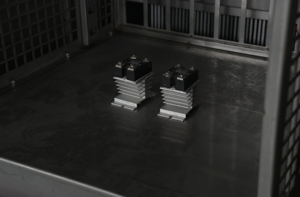
Figure 9
3.4.2 Closing the Cabinet Door
Gently close the door, ensuring it fits snugly against the weatherstrip on the cabinet with no gaps; if the door won’t close, check the position of the basket or the weatherstrip to avoid damaging the weatherstrip by forcing the door shut;
4. Operating the Touchscreen Program for High- and Low-Temperature Shock Testing
4.1 Operation Settings
Go to the “Operation Settings” screen:
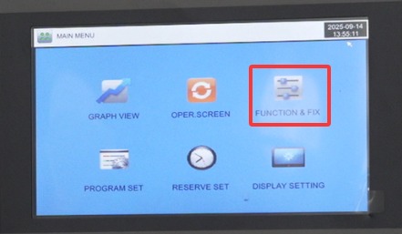
Figure 10
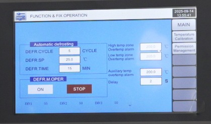
Figure 11
As shown in the figure, you can set up automatic defrosting so that the basket automatically defrosts once every five cycles; otherwise, excessive frost buildup will affect the test results. If the test is unexpectedly interrupted, you can perform a manual defrost cycle.
4.2 Appointment Settings
Go to the “Scheduling Settings” screen:
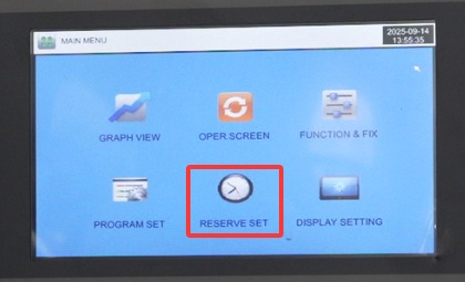
Figure 12
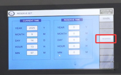
Figure 13
The
left column displays the current time, and the right column is where you can enter the scheduled time. Then, press the “Schedule” button on the far right, and the test chamber will automatically begin the impact test at the scheduled time.
4.3 Display Settings
Go to the “Display Settings” screen:
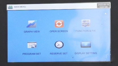
Figure 14
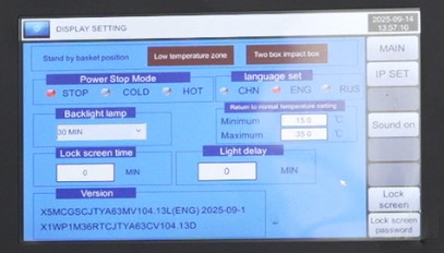
Figure 15
The main configuration parameters include the basket standby position (i.e., whether the basket is in the high-temperature chamber or the low-temperature chamber during standby); and the restart method following an unexpected power outage (Stop: An operation that returns the system to the “Stop” state when power is restored after a power outage during operation; Cold Start: After a power outage during operation, the system restarts from the first stage upon power restoration; Hot Start: After a power outage during operation, the system resumes from the stage where operation was interrupted prior to the outage, restoring the system to its pre-outage state upon power restoration); and ambient temperature range.
4.4 Program Parameter Settings (Core Section)
4.4.1 Program Settings Interface
Go to the “Program Settings” screen:
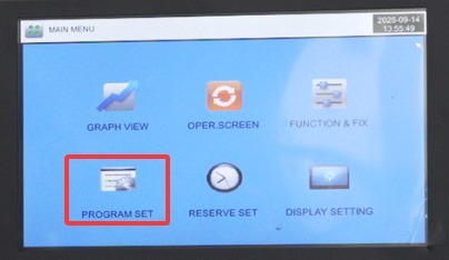
Figure 16
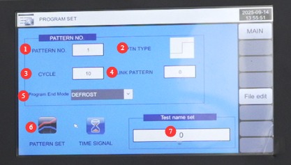
Figure 17
① “Program Group”: You can set up to 100 test groups (1–100); ② “Test Type”: From high temperature to low temperature or from low temperature to high temperature; click the image to switch; ③ “Cycles”: The number of cycles the current program will run;④ “Group Link”: If you want the current program to automatically link to another program upon completion, enter the group number for that program; if not, simply enter 0;⑤ “Program End Mode”: Select “Stop” (the unit enters standby after the program ends), “Return to Ambient Temperature” (the unit automatically cools to ambient temperature after the program ends), or “Defrost” (the unit automatically defrosts after the program ends);⑥ “Program Editing”: Edit the program to test specific parameters; see Section 4.4.2. ⑦ You can customize the name of this program.
4.4.2 Program Editing
Go to the “Program Editor” screen:
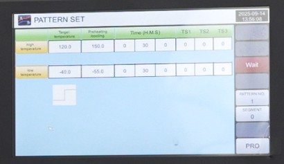
Figure 18
High-Temperature Zone: Set the “test temperature,” “preheating temperature,” and “test duration.” The preheating temperature must be 20–30°C higher than the test temperature (e.g., if the test temperature is 150°C, the preheating temperature is 170°C);
Low-Temperature Zone: Set the “Test Temperature,” “Pre-cooling Temperature,” and “Test Duration.” The pre-cooling temperature must be 10–15°C lower than the test temperature (e.g., if the test temperature is –50°C, the pre-cooling temperature is –65°C);
The TS parameter is set to “Auto,” so no changes are necessary;
If you press the “Wait” button on the right, the test time will not start counting until the set temperature is reached;
Note: All temperatures must fall within the test chamber’s design temperature range.
4.5 Program Execution and Monitoring
4.5.1 Startup Program Testing
Go to the “Monitoring Screen” interface:
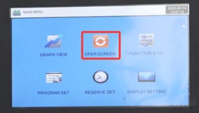
Figure 19
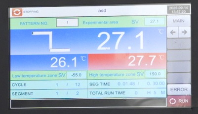
Figure 20
Verify that the program group, test name, parameters, and settings displayed on the screen match the configuration, then click the “Run” button in the lower-right corner. The device will enter program execution mode (the green light on the three-color indicator will illuminate);
If the system does not respond after clicking “Run,” check for any unresolved alarms and restart the system after resolving them.
The program begins running:
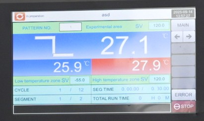
Figure 21
As shown in the figure above, the test program type is “High Temperature to Low Temperature,” so the test basket will first enter the high-temperature chamber. The setpoint displayed for the high-temperature chamber is the test temperature, while the setpoint displayed for the low-temperature chamber is the pre-cooling temperature. Once the high-temperature test is complete and the basket enters the low-temperature chamber, the setpoint for the high-temperature chamber will display as the preheating temperature, and the setpoint for the low-temperature chamber will display as the test temperature.
4.5.2 Real-Time Fault Monitoring
Alarm Notice: If a fault occurs during operation, the red light on the three-color indicator will illuminate, accompanied by a buzzer alarm, and the instrument will automatically switch to the [Real-Time Fault Display Screen]:
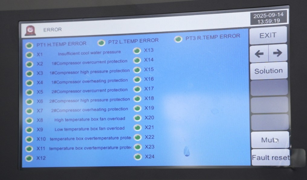
Figure 24
Note: If a problem occurs, please refer to Chapter 7 for troubleshooting.
4.5.3 Viewing Test Curves
Go to the “Curve Display” screen:
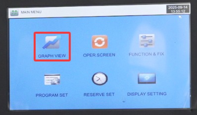
Figure 22
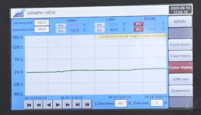
Figure 23
You
can view current and historical test curves and export them to a USB drive.
5. Post-Test Procedures
5.1 Cooling and Sample Removal
After the program has finished running, the device operates according to the “Program End Mode” setting: If set to “Return to Ambient Temperature,” wait for the device to automatically cool down to ambient temperature (20–25°C); if set to “Stop,” manually enter the “Operation Settings” screen and activate the “Return to Ambient Temperature” function;
After confirming that the temperatures in the high-temperature zone, low-temperature zone, and test zone have all dropped below 30°C, click the “Stop” button; the equipment will then enter standby mode (the yellow light on the three-color indicator will illuminate);
Open the chamber door, put on gloves, and remove the sample to avoid burns or frostbite caused by residual high or low temperatures in the sample;
Inspect the condition of the samples and record test data (such as the appearance of the samples, changes in performance, etc.).
5.2 Defrosting Procedure
Short-term retest (within 12 hours): If you need to proceed to the next test group immediately after the current test ends, tap the “Operation Settings” button on the instrument’s main screen, then tap “Manual Defrost – Start.” The unit will begin defrosting (the default defrost time is 10 minutes, but it can be set to 1–99 minutes);
Automatic Defrost: If the unit is set to “Automatic Defrost,” defrosting will automatically begin after the program ends, based on the “Defrost Cycle” (0–9999 cycles, default 0). The default defrost temperature is 15°C or 20°C, which can be adjusted based on ambient humidity;
Once defrosting is complete, the display will show “Defrost Complete.” Check that there is no residual frost inside the chamber, close the chamber door, and prepare for the next set of tests.
5.3 Shutdown Procedure
After confirming that the samples have been removed and the equipment has been cleaned, press the “Power” button on the front of the equipment to turn it off;
Turn off the power to the water-cooled unit;
If the humidity is high, open the cabinet door to ventilate for 30 minutes, then close the door;
Record equipment operating status (such as operating time, number of malfunctions, and maintenance details), and fill out the equipment usage log.
6. Routine Maintenance and Care of Equipment
6.1 Daily Cleaning and Maintenance
6.1.1 Cleaning Frequency
Clean the outer casing and inner tank before and after each use to prevent the buildup of dirt from affecting the unit’s performance;
Wipe the instrument’s touchscreen with a dry cloth before each day’s use to remove fingerprints and dust and ensure touch sensitivity.
6.1.2 Cleaning Methods
Cleaning the Chamber: Wipe down the interior of the chamber (high-temperature zone, low-temperature zone, and test zone) with a lint-free cloth moistened with alcohol to remove any residual sample stains. Do not spray water or alcohol directly onto the chamber to prevent moisture from damaging the electrical components;
Cleaning the Refrigerator Door: Wipe down the door gasket to remove dust and debris, and ensure the gasket is not deformed or damaged;
Cleaning the Exterior: Wipe down the exterior of the equipment with a dry cloth to remove surface dust. Do not use gasoline or organic solvents to prevent the paint from peeling;
Sensor Cleaning: Use a soft-bristled brush to remove dust from the surface of the temperature sensor (Type T) to prevent it from affecting the accuracy of temperature measurements.
6.2 Long-Term Decommissioning and Maintenance
6.2.1 Power-Off Procedures
Before the equipment is taken out of service for an extended period (more than 1 month), a final cleaning must be performed (inner tank, outer casing, and air vents);
Turn off the power to the equipment and the water-cooling unit, and disconnect all power circuits (circuit breakers, plugs);
Unplug the power cord and water cooling tubing, and organize the cables to prevent them from being pinched or broken.
6.2.2 Water-Cooling System Treatment
Disconnect the water-cooling tubing between the water-cooling unit and the main unit, and drain any remaining water from the tubing;
Use high-pressure gas (such as nitrogen, at a pressure of 0.2–0.3 MPa) to blow into the air inlet of the main unit’s water-cooled condenser to purge any remaining water from the cooling system (it must be completely drained to prevent ice expansion at temperatures below 0°C from damaging the refrigeration components);
Seal both ends of the water-cooled tube with caps to prevent dust from entering, and store it in a dry, well-ventilated area.
6.2.3 Dust Protection
Cover the equipment with a plastic dust cover (sized to fit the equipment) to prevent dust buildup;
Store the equipment in a dry room (relative humidity ≤ 60%, temperature 5–25°C). Do not store it in environments that are damp or contain corrosive gases;
Every 15 days, open the dust cover, ventilate the unit for 30 minutes, and check whether the inner chamber has become damp. If there is moisture, wipe it off with a dry cloth, then turn on the unit’s “Heat” function and let it run for 30 minutes to dry it out (no need to load samples).
7. Troubleshooting and Resolving Common Problems
7.1 Code and Handling for Error Screens
| Troubleshooting Codes | Possible Causes | Solution |
| X1: Insufficient Cold Water Pressure | ① The pressure of the cooling water supply is too low . ② The filter is clogged. |
① Check whether the valve at the water source is fully open . ② Clean the screen of the Y-strainer. |
| X2 Compressor No. 1 Overcurrent | ① Thermal overload reset ② Excess refrigerant, etc. |
① Press the white button on top of the thermal overload relay once to reset it. ② Check the pressure in the low-pressure line on the composite gauge. (This situation is generally rare.) |
| X3 Compressor No. 1 Overpressure | ① Poor heat dissipation in the refrigeration system. ② Excessive refrigerant was added during maintenance. ③ Insufficient cooling water pressure; check whether the chiller is operating normally, etc. |
① For air-cooled systems, check whether the condenser fan is operating normally. ② For water-cooled systems, check whether the chiller is turned on and whether the cooling water pressure is normal. ③ Using a multifunction gauge, check for excessive refrigerant and verify that frost formation on the compressor is normal. |
| X4 Compressor No. 1 Overheating | ① Bypass malfunction ② Refrigerant leak ③ Insufficient compressor oil pressure |
① Check whether the bypass solenoid valve is functioning properly. ② Check whether the refrigerant pressure is normal. (Check for leaks.) ③ Check whether the oil level in the compressor sight glass is too low. (Add refrigeration oil.) |
| X5 Compressor No. 2 Overcurrent | ① Thermal overload reset ② Excessive refrigerant, etc. |
① Press the white button on top of the thermal overload relay once to reset it. ② Check the pressure in the low-pressure line on the combination gauge. (This situation is generally rare.) |
| X6 Compressor No. 2 Overpressure | ① Poor heat dissipation in the refrigeration system. ② Excess refrigerant was added during maintenance. ③ Insufficient cooling water pressure; check whether the chiller is operating normally. ④ Refrigerant leak in Compressor No. 1; malfunction of the expansion valve on the inlet side of the plate heat exchanger or a malfunction of the check valve. |
① For air-cooled systems, check whether the condenser fan is operating normally. ② For water-cooled systems, check whether the chiller is turned on and whether the cooling water pressure is normal. ③ Using a multifunction meter, check for excessive refrigerant and verify that frost formation on the compressor is normal. ④ Check whether Compressor No. 1 is low on refrigerant. |
| X7 Compressor No. 2 Overheating | ① Bypass malfunction ② Refrigerant leak ③ Insufficient compressor oil pressure |
① Check whether the bypass solenoid valve is functioning properly. ② Check whether the refrigerant pressure is normal. (Check for leaks.) ③ Check whether the oil level in the compressor sight glass is too low. (Add refrigeration oil.) |
| X8 High-Temperature Chamber Fan Overload | ① Voltage fluctuations ② Motor malfunction |
① Measure voltage ② Use a multimeter to measure |
| X9 Cryogenic Chamber Fan Overload | ||
| X10 Test Chamber Over-Temperature Protection | ① Dial reset ② Temperature exceeds the equipment’s calibrated upper limit ③ Boiler dry burn |
① Reset the dial. ② Check whether the temperature has exceeded the design upper limit. |
| X11 Test Chamber Over-Temperature Protection |
7.2 Controller-Related Faults
| Fault Symptoms | Possible Causes | Solution |
| The controller has no digital display | 1. The power plug is not plugged in; 2. The power outlet has no power or there is a missing phase in the three-phase supply; 3. The wiring at the controller’s power supply terminals has come loose; 4. Internal controller malfunction; 5. The control cabinet door is open, causing the circuit breaker to trip. | Plug in the power cord and ensure the plug makes good contact; use a multimeter to check the outlet voltage and confirm that the AC 380 V is normal and that all three phases are present; open the control cabinet door, inspect the controller’s power supply wiring (24 VAC/DC), and retighten any loose terminals; If the display remains blank despite proper wiring, contact the manufacturer to repair or replace the controller; Close the control cabinet door, reset the circuit breaker (located inside the control cabinet door), and confirm that it has closed. |
| The numbers on the controller display are fluctuating erratically | 1. Loose connection in the temperature sensor (Type T); 2. Damaged platinum resistance or poor solder joint; 3. Significant power supply interference (e.g., high-power equipment nearby); 4. Internal circuit failure in the controller | Check the sensor connections (PT1 for the high-temperature zone, PT2 for the low-temperature zone, and PT3 for the test zone), unplug and replug them, and secure them; Use a multimeter to measure the resistance of the platinum resistance thermometers (approximately 100 Ω at room temperature); if the resistance is abnormal, replace them with the same model; Keep the equipment away from high-power devices, or install a power filter for the equipment; Contact the manufacturer to service the controller and replace it if necessary. |
| PLC Communication Error (Displays “PLC no response”) | 1. Loose or broken communication cables between the controller and the PLC; 2. Damage to the communication interface (such as RS485); 3. Abnormal PLC power supply | Check the communication cables (signal lines), unplug and replug them securely, and replace any broken cables; use a multimeter to check the voltage at the communication interface and confirm it is normal (24V); if the interface is damaged, replace it; check the PLC power supply to ensure normal power delivery (24V DC); if there is an issue with the power supply, repair the PLC power supply module. |
7.3 Heating/Cooling Malfunctions
| Fault Symptoms | Possible Causes | Solution |
| No heating | 1. Over-temperature protection triggered (buzzer alarm); 2. Set temperature is lower than the actual measured temperature; 3. Solid-state relay (SSR) failure; 4. Heater (ceramic heating element) failure; 5. Open circuit in the platinum resistance thermometer (no temperature feedback); 6. No heating output signal from the controller | Access the fault screen to reset the over-temperature protection, then reset the over-temperature threshold (20°C higher than the test temperature); reset the temperature setting, ensuring the setpoint is higher than the actual temperature; use a multimeter to test the solid-state relay (SSR) output terminals; if there is no voltage, replace the SSR with one of the same model; Measure the heater resistance (approximately several tens of Ω at room temperature); if the resistance is infinite, replace the heater; Check the platinum resistance wire connections; if there is an open circuit, re-solder or replace them; Go to the controller’s “Output Monitoring” screen; if there is no output, repair the controller |
| Heating Runaway (Continuous Temperature Rise) | 1. The set temperature is too high (exceeding the unit’s upper limit of 150°C); 2. The solid-state relay is stuck (unable to open); 3. The platinum resistance thermometer is shorted (abnormal temperature feedback); 4. Controller malfunction (abnormal output signal) | Immediately turn off the power and reset the temperature to within the device’s permissible range; Replace the solid-state relay and check the output terminals for short circuits before turning the power back on; Inspect the platinum resistance thermometer; if a short circuit is found, replace it; Contact the manufacturer to have the controller repaired or replaced if necessary. |
| Not cooling | 1. The cooling switch is not turned on (on the “Operation Settings” screen of the instrument); 2. The controller’s timing signal is set incorrectly or the program is not running; 3. The compressor has not started (power supply or phase sequence issues);4. Freon leak (low pressure in the refrigeration system); 5. Blockage in the refrigeration lines | Go to the “Operation Settings” screen and turn on the cooling switch; Check the program sequence settings to ensure the cooling phase is operating normally; Check the compressor power supply and phase sequence; after confirming they are normal, wait 3–5 minutes before restarting; Contact the manufacturer to locate the leak; after repairing the leak, evacuate the system again and recharge it with refrigerant; Disassemble the refrigeration piping and clean any clogged components (such as the dry filter); replace them if necessary. |
| Slow cooling (temperature drops slowly) | 1. Freon leak (low pressure); 2. Blockage in the refrigeration piping system (e.g., clogged filter); 3. Excessive moisture in the chamber (icing impairs heat dissipation); 4. Low cooling efficiency of the water-cooled unit (excessively high water temperature, insufficient water flow) | Check the Freon pressure; if it is low, recharge the system; replace the clogged dry filter and capillary tube; Use a clean cotton cloth to wipe the moisture from the inner tank, then activate the “Heating” function to dry it for 30 minutes before lowering the temperature; check the water temperature (normally 20–25°C) and flow rate of the water-cooled unit, and adjust them to the normal range |
7.4 Other Common Problems
| Fault Symptoms | Possible Causes | Solution |
| The case is live | 1. Poor protective grounding (loose grounding wire, grounding resistance exceeds specifications); 2. Internal wiring disconnection (live wire coming into contact with the chassis); 3. Poor heater insulation (electrical leakage) | Check the ground wire, secure it again, and use a Grounding Resistance Tester to verify that the resistance is ≤50 Ω; Open the control cabinet door, inspect the internal wiring, and reattach any loose live wire terminals; Measure the heater’s insulation resistance; if the insulation is defective, replace the heater. |
| Chiller Malfunctions | 1. Overload in a cold unit (compressor current exceeds 1.2 times the rated value); 2. Overpressure (excessively high ambient temperature, cooling pressure exceeds the limit); 3. Water-cooled unit system failure (e.g., water pump failure, condenser blockage) | Reset the overload protection setting to 1.2 times the compressor’s rated power, then restart the unit after resetting; if the overload persists, contact customer service; improve ventilation (e.g., by installing a fan) and lower the ambient temperature to below 30°C; check the water pump’s operating status and the condenser for blockages; if necessary, contact the water-cooled unit manufacturer’s customer service. |
| The basket lift is stuck | 1. Insufficient air supply pressure (normal range: 0.5–0.8 MPa); 2. Cylinder malfunction (air leak, piston jam); 3. Contaminants or dust on the basket guide rails; 4. Malfunction of the three-position, five-way solenoid valve | Adjust the air supply pressure to the normal range and drain the condensate from the air filter; Check the cylinder for leaks; if there are any, replace the cylinder seal; if the cylinder is sticking, disassemble and clean it; Clean the guide rails with an alcohol-soaked lint-free cloth and apply a small amount of lubricant (compatible with the guide rail material); Check the solenoid valve’s output signal; if faulty, replace the solenoid valve |
| Poor door seal (temperature leakage) | 1. The weatherstripping has aged or warped; 2. The cabinet door hinges are loose, causing the door to be crooked; 3. The cabinet door lock is not adjusted properly | Replace worn-out weatherstripping and ensure it fits snugly; adjust the door hinge bolts to ensure the door is vertical and does not tilt; turn the door lock knob to adjust the tension of the lock, ensuring the door closes tightly. |
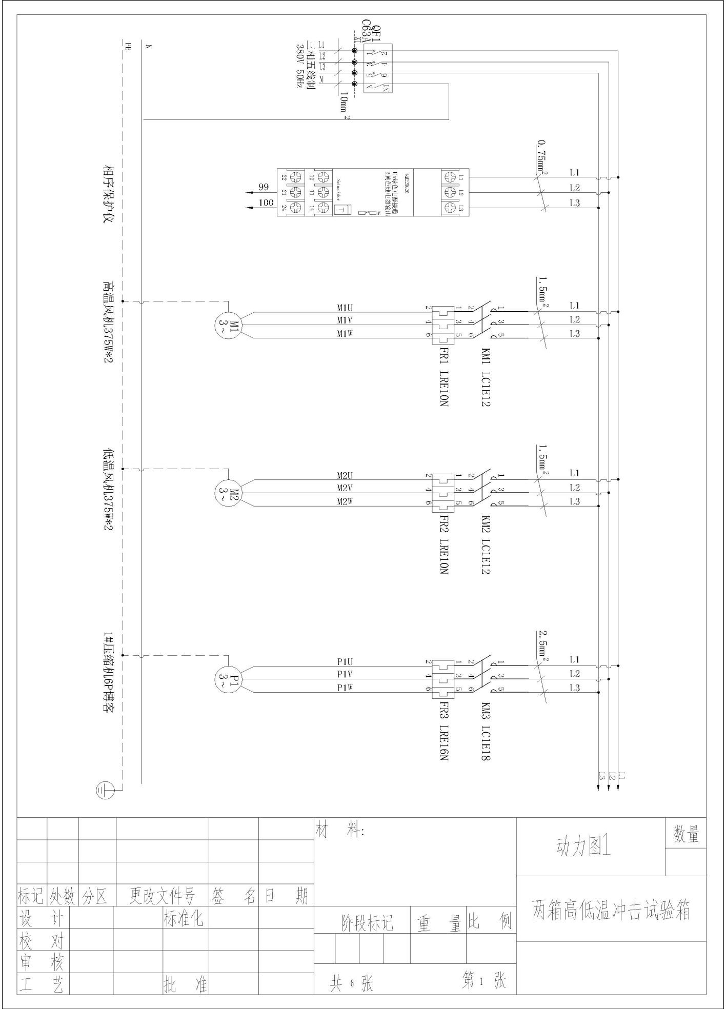
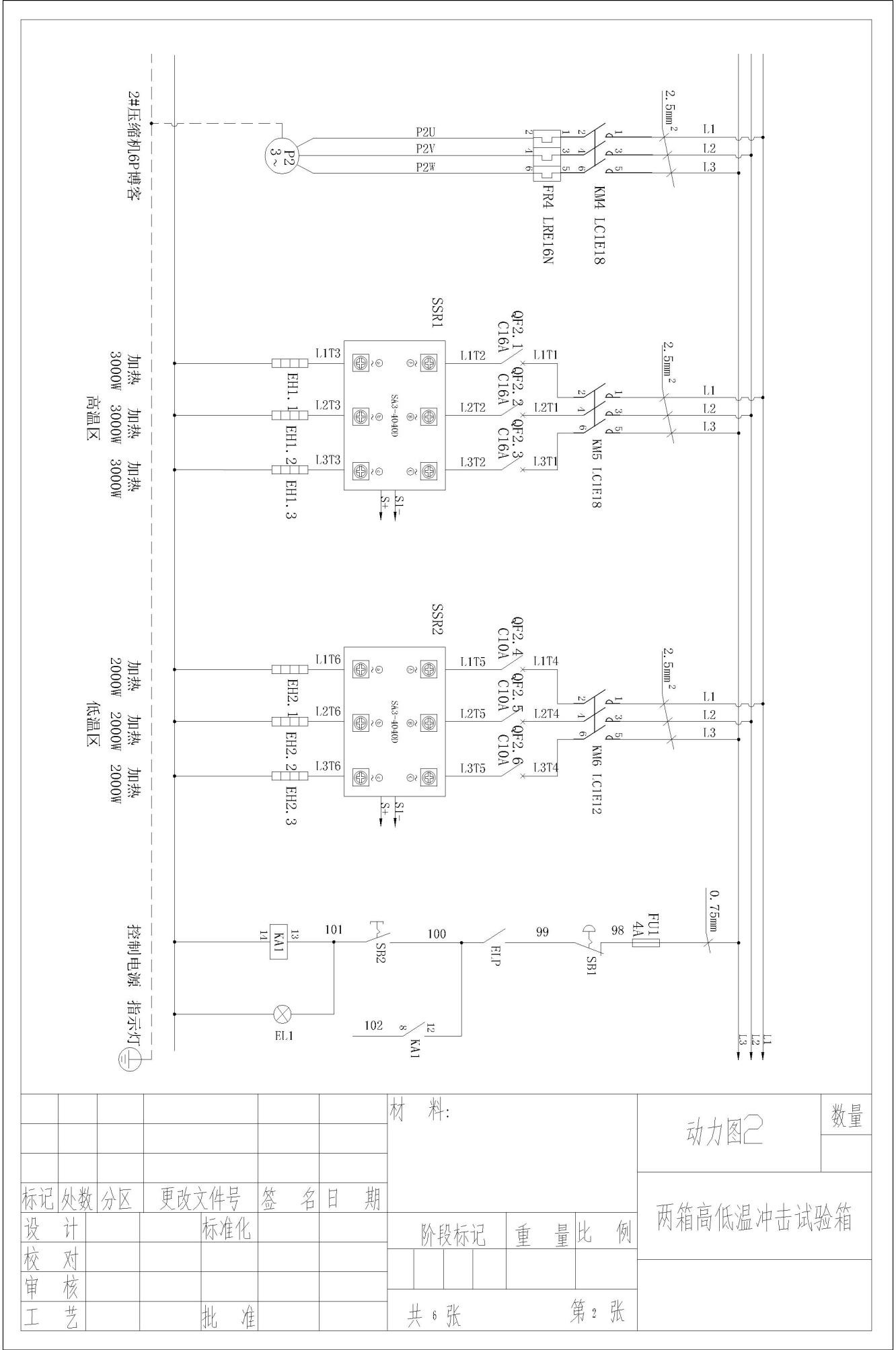
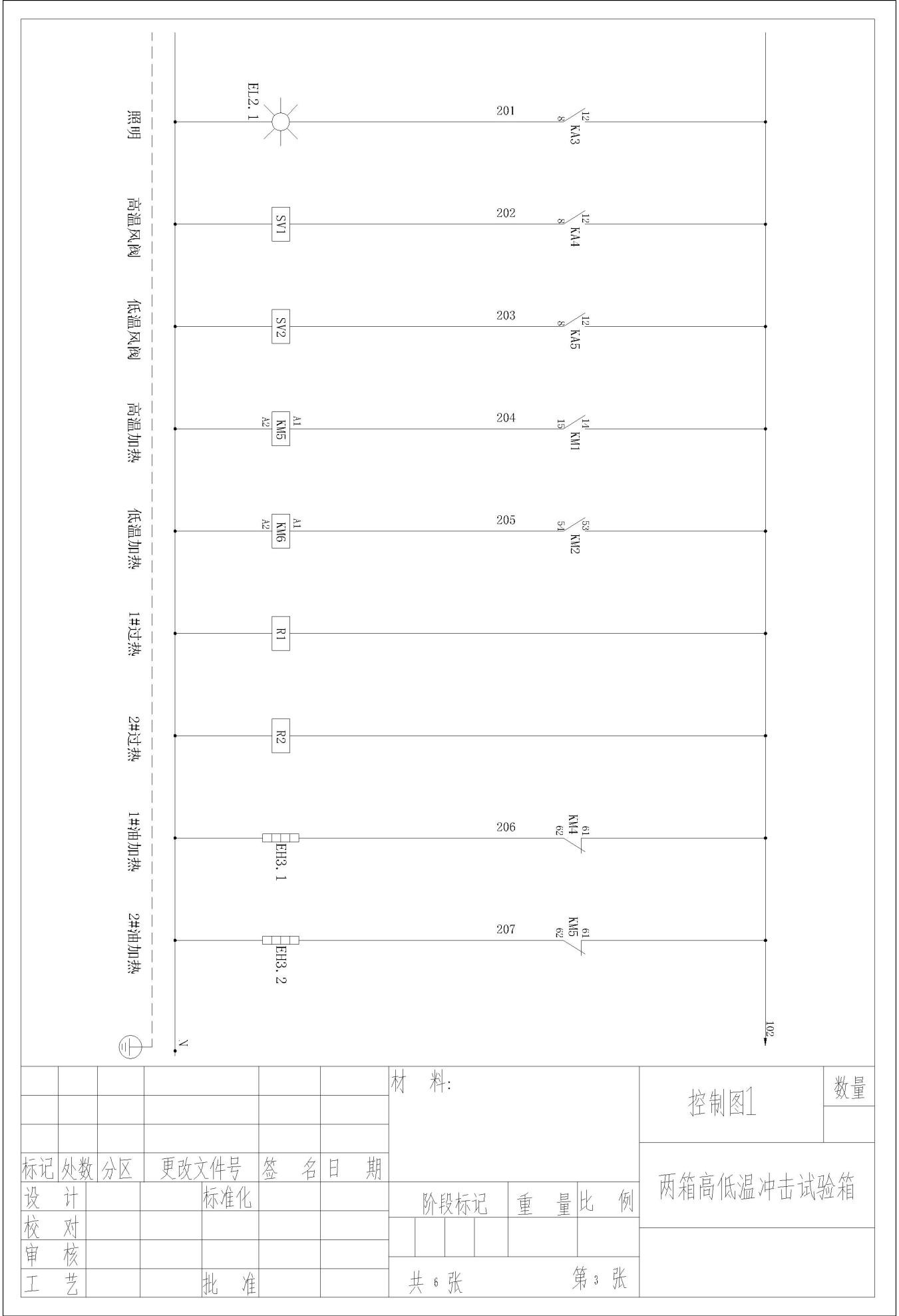
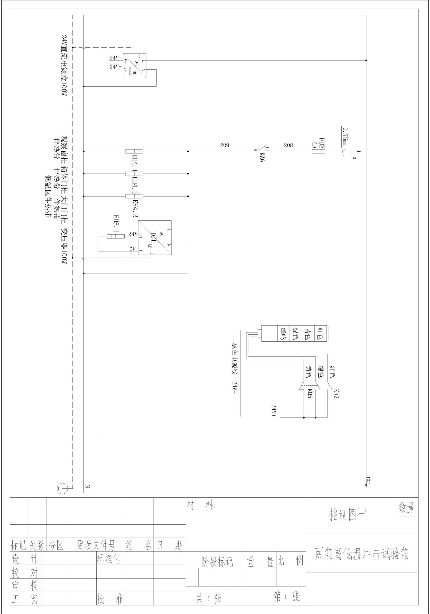
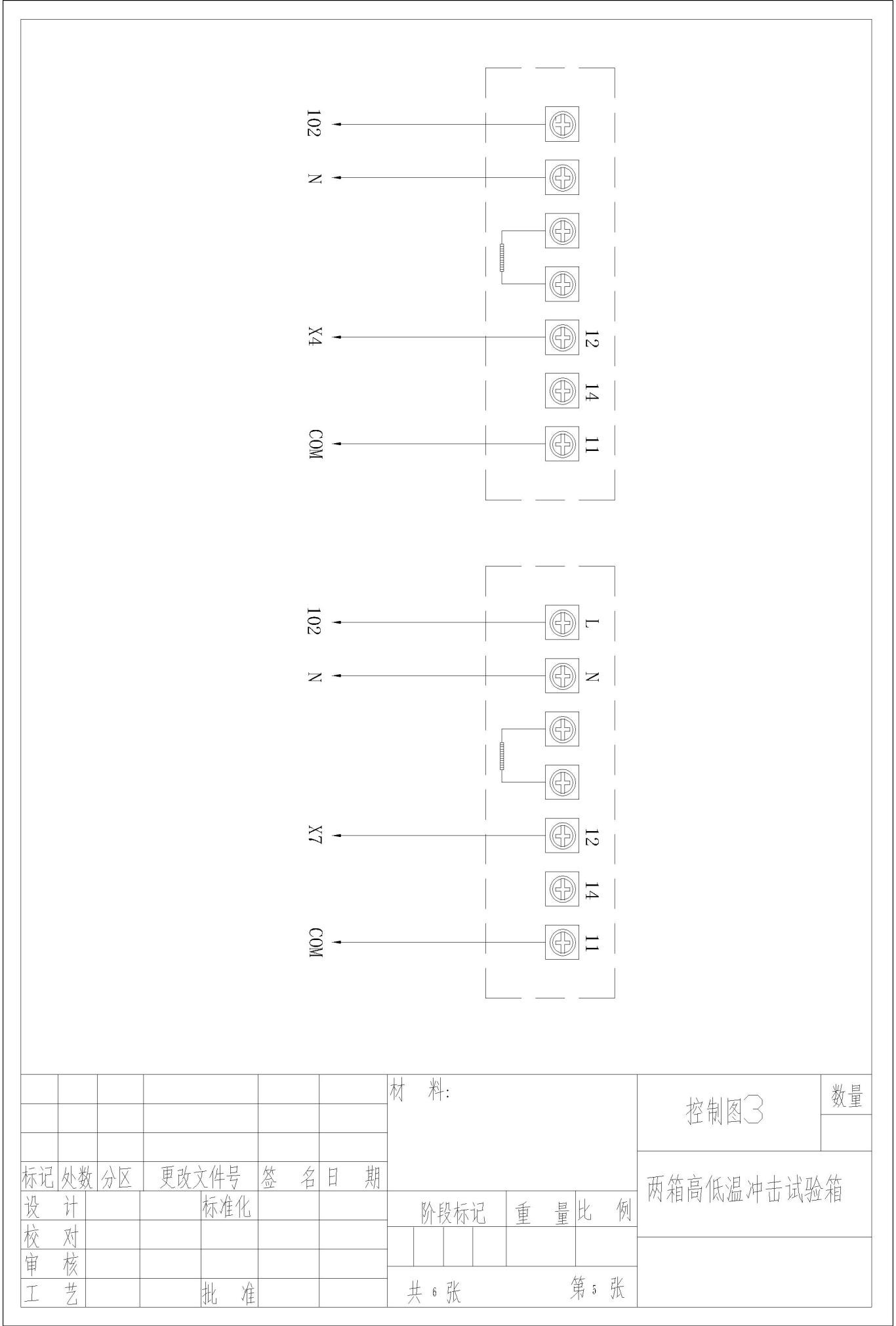
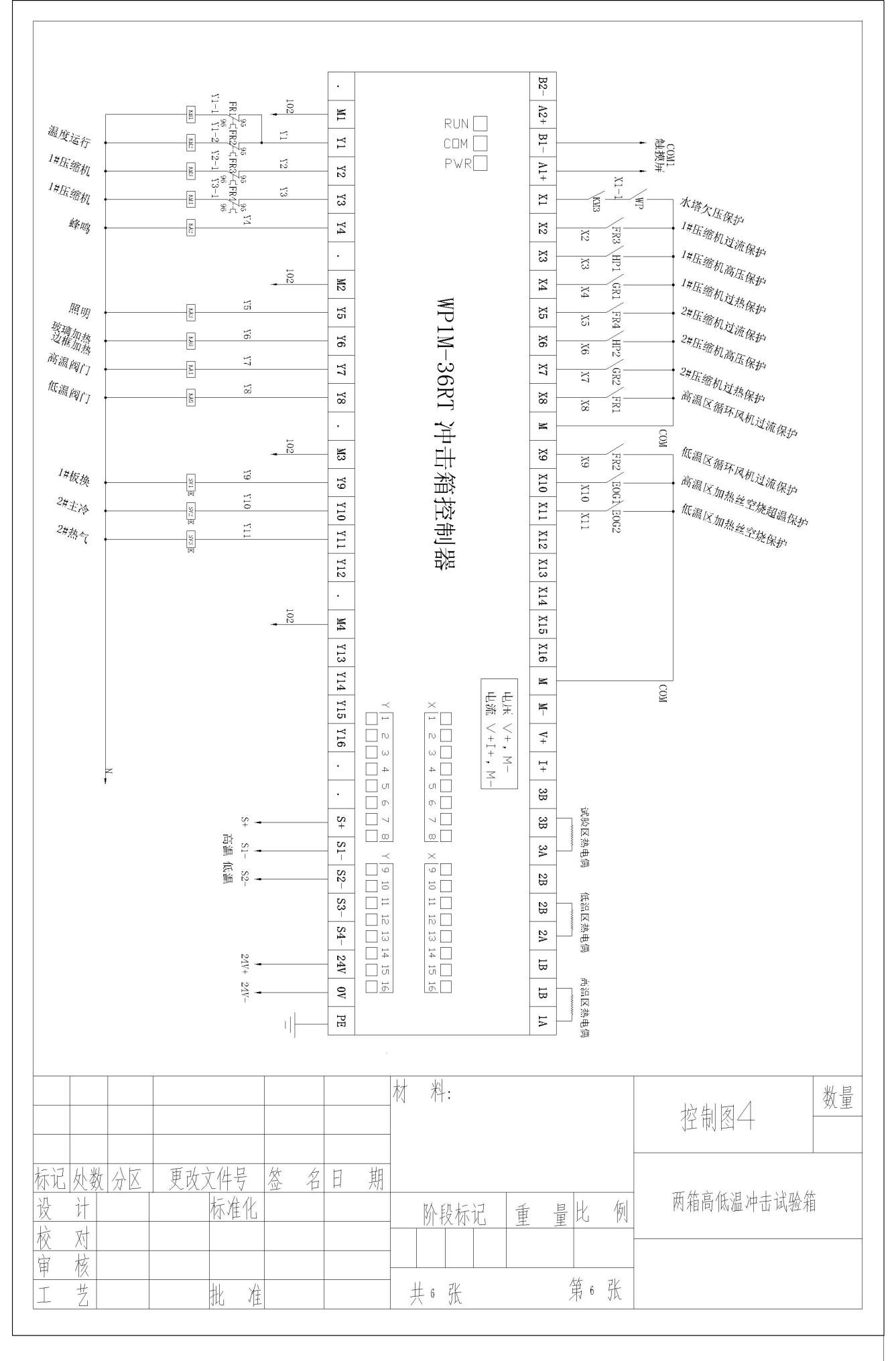
Appendix: Circuit Diagram