
 English
 中文简体
中文简体 English
 Русский
 Español
 Português
 Türkçe
 العربية
 Deutsch
 Polski
 Italiano
 Français
 한국어
한국어 ไทย
ไทย Tiếng Việt
 日本語
日本語





























Black Test Corner | Temperature Rise Test Corner
User's Manual
Applicable LISUN models: TMPWS-010、TMPWS-012、TMPWS-014、TMPWS-020
1. Unboxing and Basic Familiarization with the Equipment
1.1 Key Technical Specifications
| LISUN Model | TMPWS-010 | TMPWS-012 |
| Internal Dimensions (Length × Width × Height) | 1000 mm × 1000 mm × 1000 mm | 800 mm × 1000 mm × 1500 mm |
| Plywood Wall Thickness | 20 mm (high thermal insulation, reduces the impact of external temperatures) | 21 mm (high thermal insulation, reduces the impact of external temperatures) |
| Number of Type K Thermocouples | 243 pieces (evenly distributed on the inner wall of the test corner and the sample support area) | 287 pieces (evenly distributed on the inner wall of the test corner and the sample support area) |
| Specifications for Temperature-Sensing Copper Plates | 15 mm in diameter, 1 mm thick (brass, uniform heat conduction, meets standard requirements) | |
| Temperature Measurement Accuracy | ±0.5°C (within the -50°C to 300°C range) | |
1.2 Unboxing and Inspection
1.2.1 Unpacking and Visual Inspection
Before unpacking, check the outer packaging for any damage, deformation, or signs of moisture. After unpacking, remove the packing materials and inspect the exterior of the equipment for any damage, such as dents, scratches, or loose parts. If any of the above issues are found, please document them immediately and contact us.
1.2.2 Main Unit and Accessories
Black Test Corner | Temperature Rise Test Corner: 1 unit. No other accessories.
Note: Customers must provide their own Multiplex Temperature Tester for use with the Black Test Corner Temperature Rise Test Corner.
Download links for the digital user manual, warranty card, and other documents have been sent to you via email. Please download them as soon as possible. If you missed the email, please feel free to contact us to request the download links again.
1.3 Description of Equipment Structure
① The bottom three sides of the unit feature Omega Type K thermocouple sockets, which must be connected to a Multiplex Temperature Tester to view the real-time temperature readings from the corresponding thermocouples; ② The interior of the unit on three sides is equipped with Type K thermocouples, which are used to monitor real-time temperature.
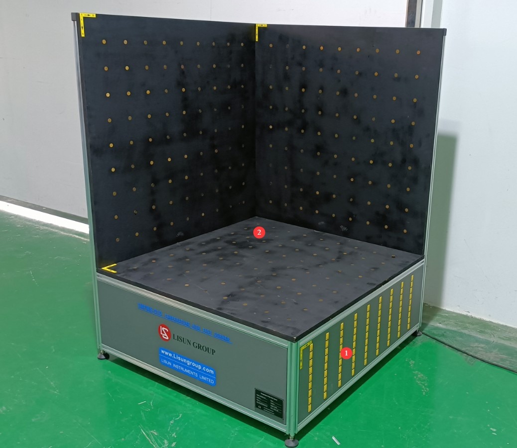
Figure 1
Note: Follow the arrows on the labels to match each thermocouple jack with its corresponding thermocouple.
2. Safety Precautions
2.1 Operational Safety
The surface of the device may become hot during testing. Do not touch the temperature-sensing copper plate, the test surface, or the sample being tested with your bare hands to prevent burns.
Do not step on the base plate during testing under any circumstances, as this may damage the internal structure and temperature-sensing components, thereby affecting test accuracy.
While the equipment is in operation, an operator must be present to monitor it and prevent non-authorized personnel from approaching or touching the equipment.
2.2 Environmental Safety
The equipment must be placed in an environment with no significant airflow, away from heat sources (such as radiators and ovens), and out of direct sunlight to prevent heat radiation from interfering with the test results.
The installation location must be kept away from hazardous materials such as flammable, explosive, and corrosive gases, and the test environment must be well-ventilated.
The surface where the equipment is placed must be level and sturdy to prevent the equipment from tipping over or test samples from sliding off due to unevenness.
3. Preparations Before the Test
3.1 Preparing the Environment
Adjust the temperature of the test environment to 25°C (recommended value) and maintain the humidity between 40% and 70% RH. Use a thermo-hygrometer to verify that the environmental parameters meet the requirements.
Clear any obstacles around the equipment, ensure that the distance between the equipment and the wall is at least 100 mm, and ensure adequate airflow without significant airflow interference.
Turn off air conditioners, fans, and other equipment that generates airflow within the test environment to avoid disrupting the thermal equilibrium.
3.2 Component Connections and Inspection
Connect the Type K thermocouple jacks to the Multiplex Temperature Tester one by one in order, ensuring that the connections are secure and free of looseness or poor contact.
After turning on the power to the Multiplex Temperature Tester, wait 15 minutes for the device to reach thermal equilibrium. Check the temperatures at each measurement point using the control panel or the accompanying software to confirm that the maximum temperature difference is ≤1.5°C.
If the temperature difference exceeds the specified limit, recheck the environmental conditions and thermocouple connections; proceed with subsequent operations only after resolving the issue.
3.3 Preparation of Test Specimens
Inspect the test sample to ensure there are no visible damages or deformations, that its electrical performance is intact, and that it meets the requirements for its initial state prior to testing.
Pre-treat the samples in accordance with the relevant standards (for example, for some products, the supply voltage must be increased to 1.15 times the rated voltage; refer to the corresponding product standards for details).
Prepare sample-holding devices (such as stands and clamps) to ensure that the sample is positioned in accordance with the standard requirements, as close as possible to the three faces of the test corner (if the standard specifies special requirements, please refer to the corresponding standard). Take care to prevent the sample from shifting during the test.
4. Temperature Rise Test Procedure
4.1 Setting Test Parameters
4.1.1 Basic Parameter Configuration
Select the range of temperature measurement points based on testing requirements; you can choose either all measurement points or those in a specified area.
Focus on the temperature measurement points corresponding to the areas of the sample where heat is generated to ensure that temperature rise data from critical areas is accurately recorded.
4.1.2 Multiplex Temperature Tester Configuration
Open the Multiplex Temperature Tester’s control panel or the accompanying test software, and configure the settings according to your specific needs—such as channel selection, test duration, and data logging interval.
4.2 Test Initiation
First, activate the temperature logging function on the Multiplex Temperature Tester, then start the sample run according to the standard. Use the Multiplex Temperature Tester to record changes in ambient temperature throughout the entire sample run.
4.3 Precautions During the Test Procedure
During testing, do not arbitrarily adjust the position of the sample, change test parameters, or touch critical components of the equipment.
Keep the test environment stable; avoid frequent entry and exit by personnel or turning on equipment that creates air currents.
If the test is lengthy, check the device’s power supply and data storage status periodically to ensure continuous and stable operation.
Strictly follow the test requirements specified in the corresponding product standards; do not shorten or extend the test duration without authorization.
5. Post-Test Procedures
5.1 Termination of the Test
Once the preset test duration has elapsed, stop the Multiplex Temperature Tester and save all temperature data. Stop the sample according to normal operating procedures and shut it down.
5.2 Data Organization and Storage
Compile all test data, including temperature readings at each measurement point at different times, the initial temperature, the peak temperature rise, and so on.
Analyze the test results in accordance with the product standards and determine whether the temperature rise of the sample complies with the standard requirements.
Organize and archive test data, analysis results, and records of the testing process for future reference.
6. Daily Maintenance and Care of Equipment
6.1 Daily Maintenance
Clean the surface of the equipment and wipe the test surface with a dry, soft cloth to remove dust and stains. Do not use corrosive cleaning agents.
Check that the thermocouple connection wires are intact and that the connectors are secure. If there is poor contact, unplug and replug the connectors or replace them.
6.2 Weekly Maintenance
Check the condition of the temperature-sensing copper plate to ensure there is no loosening, deformation, oxidation, or detachment; if oxidation is present, gently wipe away any surface residue.
Clean the dust from the bottom and around the equipment, and check that the drive wheel fasteners are secure; if any are loose, tighten them immediately.
6.3 Monthly Maintenance
Perform accuracy calibration on Type K thermocouples by comparing data from each measurement point using standard temperature measurement instruments. If the error exceeds ±0.5°C, replace the thermocouple promptly.
Inspect the test surface to ensure the coating is intact. If there is any flaking of the matte black paint, contact the manufacturer to have it touched up to ensure compliance with the standard requirements.
6.4 Long-Term Decommissioning and Maintenance
If the equipment will not be used for an extended period (more than one month), after completing routine cleaning, cover it with a dust cover to prevent dust buildup, and store it in a dry, well-ventilated area to avoid moisture or direct sunlight.
7. Troubleshooting and Resolving Common Problems
7.1 Temperature difference exceeds the limit (>1.5°C)
Symptom: After the equipment has reached thermal equilibrium, the temperature difference between measurement points or between a measurement point and the reference temperature exceeds 1.5°C.
Possible causes:
The test environment has noticeable airflow or is subject to thermal radiation interference; thermocouple connections are loose, have poor contact, or some thermocouples are damaged; the coating on the test surface has peeled off, affecting the thermal radiation characteristics.
Troubleshooting and Resolution:
Inspect the test environment; turn off fans, air conditioners, and other equipment; block direct sunlight; and ensure the environment meets the requirements. Check each thermocouple connection one by one; unplug and replug the connectors to ensure a secure connection; and replace any damaged thermocouples. If the coating on the test surface has peeled off, contact the manufacturer for professional touch-up work; suspend use until the issue is resolved.
7.2 No Signal from the Thermocouple
Symptom: Although the external cable connections have been confirmed to be secure, the Multiplex Temperature Tester for this channel is not displaying any temperature data.
Possible causes: A break in the thermocouple cable inside the Black Test Corner | Temperature Rise Test Corner or damage to the socket; the thermocouple is not properly connected to the socket; the thermocouple itself is damaged.
Troubleshooting and Resolution: Check the thermocouple cable for damage or breaks, and replace any damaged cables; unplug and reinsert the thermocouple into the socket to ensure a secure connection; if the socket is damaged, contact the manufacturer to have it replaced; replace the thermocouple.