
 English
 中文简体
中文简体 English
 Русский
 Español
 Português
 Türkçe
 العربية
 Deutsch
 Polski
 Italiano
 Français
 한국어
한국어 ไทย
ไทย Tiếng Việt
 日本語
日本語





























Power Cord Bending Tester
User's Manual
Applicable LISUN models: SW-1、SW-2、SW-6
1. Unboxing and Basic Familiarization with the Equipment
1.1 Key Technical Specifications
| LISUN Model | SW-1 | SW-2 | SW-6 |
| Test Station | Single-station | Two stations | Six-station |
| Electrical Control Methods | PLC-based intelligent integrated control, 7-inch touchscreen HMI | ||
| Drive Type | Servo Motor Drive | ||
| Specimen Clamping Methods | Mechanical clamping; adjustable clamping points | ||
| Bend Angle | Adjustable from 0 to 360° (with preset angles of ±30°, ±45°, ±60°, and ±90°) | ||
| Bending Rate | 0–60 cycles per minute (variable-frequency speed control) | ||
| Number of bends | Can be preset from 0 to 999999 (default: 25 times) | ||
| Load Weights | 1 set of weights; 5 N, 10 N, 20 N | 2 sets of weights: 5 N, 10 N, 20 N | 6 sets of weights: 5 N, 10 N, 20 N |
| Load Power Supply | Load current: 0–20 A (adjustable) | ||
| Test Evaluation | Determining based on the signal indicating whether current is flowing | ||
1.2 Unboxing and Checking the Contents
1.2.1 Unpacking and Visual Inspection
When unpacking the device, handle it gently to avoid scratching the outer casing with sharp tools. After unpacking, first inspect the exterior of the device to ensure there is no visible deformation or dents, and that the buttons are not damaged or loose.
If you notice any damage or deformation to the equipment or accessories, do not turn on the power. Please contact us immediately.
1.2.2 Main Unit and Accessories
Power Cord Bending Tester: 1 unit.
Standard accessories are as follows: ① Spare fixtures; ② Weights.
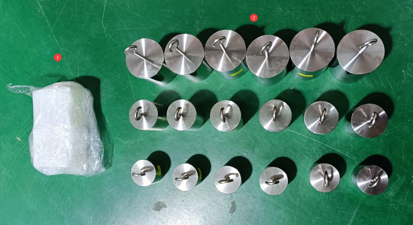
Figure 1
Note: Each workstation is equipped with one set of weights; each set includes three weights: 5N, 10N, and 20N.
Download links for the electronic user manual, warranty card, and other documents have been sent to you via email. Please download them as soon as possible. If you missed the email, please feel free to contact us to request the download links again.
1.3 Description of Equipment Structure
1.3.1 Front of the Device
① The two circuit breakers here are for loads; the one with ground-fault protection is for the equipment and simulated load circuit breakers; ② The other is for the actual load circuit breaker; ③ When testing with an actual load, the load voltage is displayed here; ④ Emergency stop switch: Before turning on the power, turn it clockwise to ensure the emergency stop switch is released;⑤ Equipment power switch; ⑥ When using a simulated load, the simulated load current for the corresponding station is displayed here; ⑦ Turntable and fixtures (Note: Regardless of whether a sample is installed, all stations will rotate simultaneously during testing);⑧ Used to ensure that the power cord and weights do not swing too widely during the test; ⑨ Live load connector; ⑩ Simulated load terminal block (Note: The jumper wires shown in the image are used for equipment testing and are not required during actual operation); ⑪ Used to adjust the simulated load current for the corresponding workstation.
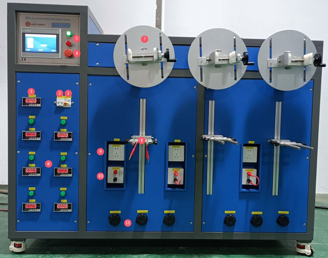
Figure 2
1.3.2 Back of the Device
① Equipment power cord; ② Sample actual load power cord.
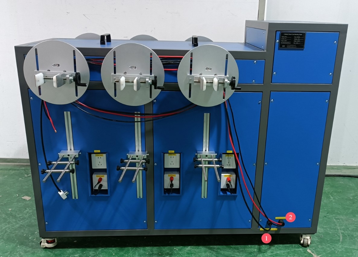
Figure 3
Note: When testing with a real load, the test specimen must be connected to a separate power source; when testing with a simulated load, the test specimen does not need to be connected to a power source, as the equipment provides the test current.
1.3.3 Side of the Device
Used to display the current angle of the turntable.
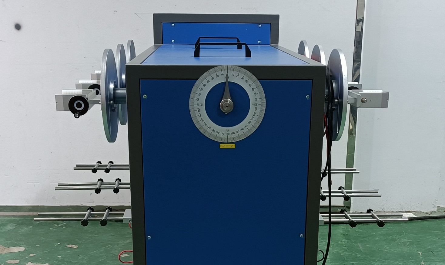
Figure 4
Note: Single-station and two-station models do not have this feature; the touchscreen program includes an angle display function.
2. Safety Precautions
2.1 Electrical Safety
2.1.1 Power Connection
220V single-phase power; power outlets must comply with safety standards, have proper grounding, and have a rated current that matches the device’s power rating and the actual load power requirements.
2.1.2 Grounding Specifications
The equipment must be reliably grounded, with a grounding resistance of ≤4 Ω. Do not use gas pipes, non-metallic water pipes, or the neutral wire as a substitute for the grounding wire. After grounding is complete, use a Grounding Resistance Tester to measure the grounding resistance. Do not energize the equipment until you have confirmed that it meets the requirements, to avoid electric shock, equipment malfunction, or measurement errors caused by poor grounding.
2.2 Operational Safety
Before wiring, inspecting, or maintaining equipment, you must turn off the equipment’s power switch and the main power supply, and confirm that there is no residual voltage before proceeding;
Do not operate the equipment’s power switch, touchscreen, or instrument buttons with wet hands to avoid the risk of electric shock;
Do not place any foreign objects (such as tools or paper) inside the electrical control cabinet to prevent dust or foreign objects from causing short circuits or damaging components;
Do not plug in or unplug power cords or signal cables while the equipment is running to prevent short circuits that could damage the controller or electrical components;
If any abnormalities occur during the test (such as a test specimen falling off, unusual noises from the equipment, or abnormal current), immediately press the emergency stop switch to cut off the power supply; restart the equipment only after troubleshooting the problem;
Select weights that meet the test requirements, and ensure they are securely installed to prevent them from falling during the test and causing injury to personnel or damage to equipment; for non-standard tests, the weight of a single-station weight must not exceed 35 N;
During testing, the turntable and fixtures are in rotation. Do not touch them with your hands or place any foreign objects on them to prevent entanglement and personal injury;
Strictly distinguish between the wiring methods for simulated loads and actual loads. Do not plug them into the wrong sockets (simulated loads must be connected to the terminals, and actual loads to the designated sockets); otherwise, this may cause circuit breakers to trip, short circuits, or equipment damage.
2.3 Environmental Safety
The equipment should be placed in a dry environment free of corrosive gases and flammable or explosive materials.
The equipment must be installed in an air-conditioned room, with the ambient temperature maintained between 5°C and 35°C and relative humidity ≤ 85%.
The distance between the equipment and walls and surrounding structures (such as other testing equipment and shelving) must be at least 1000 mm to facilitate operation and maintenance; at least 2000 mm of space must be left in front of the equipment to ensure smooth operation and that there are no obstructions in the surrounding area;
The equipment must be placed on a level, solid surface; the height of the equipment’s legs is adjustable.
2.4 Other
For matters not covered in this manual, please proceed with caution or contact us.
3. Introduction to the Touchscreen Program
3.1 Test Interface
① Start Test; ② Stop Test; ③ Manual Forward Rotation; ④ Manual Reverse Rotation; ⑤ Return to Zero; ⑥ Number of Tests; ⑦ Clear; ⑧ Parameter Settings; ⑨ Open/Closed Detection.
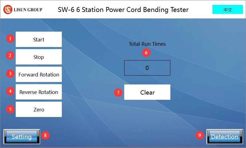
Figure 5
Note: Steps ③ and ④ are used to rotate the turntable to the appropriate angle for installing the sample. Once the sample is installed, click “Return to Zero” to automatically rotate the turntable back to the 0-degree position.
3.2 Parameter Settings Page
① Test speed; ② Reverse angle; ③ Forward angle; ④ Total number of tests.
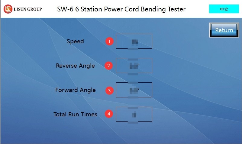
Figure 6
Note 1: Test speed; the time specified is the time required to complete one test.
Note 2: Forward rotation by a specified angle followed by return + reverse rotation by a specified angle followed by return = one test.
3.3 Circuit Continuity Test Interface
① Number of tests performed; ② Station number—if this station is performing a load test (simulated or actual load), press the button for that station to switch it to green, which indicates that the current at that station is being monitored;③ If current cannot be detected at a load-testing station during a test, the count for that station is incremented by one; ④ Reset: Resets the count for the corresponding station to zero.
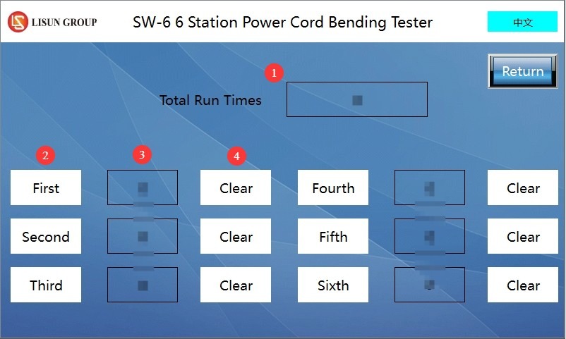
Figure 7
4. Preparations Before the Test
4.1 Confirmation of Test Standards
Based on testing requirements, clearly define the applicable execution standards. The following are common standards and their key requirements:
| Standard Number | Standard Terms and Conditions | Applicable Scenarios | Key Test Parameters |
| GB/T 2099.1-2021 | Article 23.4 | Non-detachable plugs, portable power strips | Load capacity: 20 N (for flexible cables with a cross-sectional area > 0.75 mm²), 10 N (for others); Bending angle: ±45° (total 90°); Number of bending cycles: 10000; Bending rate: 60 cycles/min; Power Supply Requirements: Rated current or specified current (16 A/10 A/2.5 A) |
| GB/T 3883.1-2014 | Article 24.12 | Tools where the power cord bends during operation | Load capacity: 10×Dc + 2g (where Dc is the outer diameter of the flexible cable, in mm); Radius of curvature: ≥1. Dc; Length of flexible cable sheath protrusion: ≥5 times the outer diameter of the flexible cable |
| GB/T 4706.1-2024 | Article 25.14 | Portable Appliances with Power Cords | Load capacity: 10 N (for flexible cables with a cross-sectional area > 0.75 mm²), 5 N (for others); Bending angle: ±45° (total 90°); Bending cycles: 10000 cycles (standard connection), 20000 cycles (Z-type connection); Bending rate: 60 cycles/min; Electrical requirements: rated voltage, rated current (without passing through the ground conductor) |
4.2 Sample Preparation
Select a new, untested power cord as the test specimen, ensuring that the specimen is free of damage, the insulation is free of cracks, the conductor is free of oxidation, and that its specifications and parameters comply with the test requirements (such as the cross-sectional area of the flexible cable and the rated voltage/current).
5. Operating Procedures for the Power Cord Bending Test
5.1 Testing with a Simulated Load
5.1.1 Sample Installation and Commissioning
① Clamp the end of the sample power cord to be tested—that is, the end with the insulation—here. Note: You must properly short-circuit the L and N terminals on this end of the power cord to generate a simulated current. ② Connect the other end of the sample power cord to the red and black terminals. ③ Attach an appropriate weight to the power cord and thread it through the small hole to prevent the cord from swinging during the test.
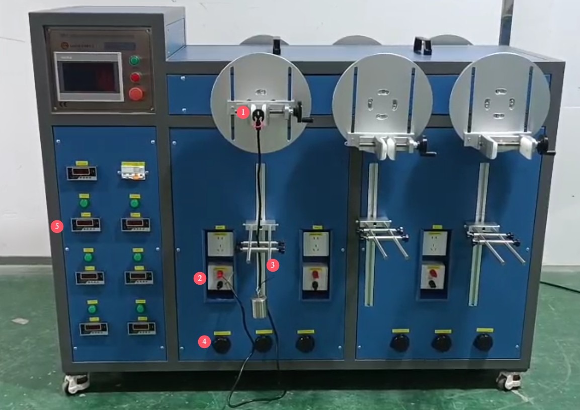
Figure 8
After the device’s power cord is properly connected, turn on the device. ④ Use the knob to adjust the test current; ⑤ The current flowing through the power cord is displayed here.
5.1.2 Test Parameter Settings
Configure the settings as described in Sections 3.2 and 4.1.
5.1.3 Operational Testing
On the “Circuit Detection” page, press the number key corresponding to the workstation to monitor its load current. Reset the count for all workstations to zero.
On the “Test” screen, click “Reset” or “Return to Zero,” then click “Start Test” to begin the test. During the test, you can go to the “Continuity Test” screen to view real-time data for all stations.
The test stops automatically once the set number of test cycles has been completed or when no current is detected at any of the loaded test stations.
5.2 Testing with Real-World Workloads
5.2.1 Sample Installation and Commissioning
① Clamp your test appliance—such as a hair dryer—here; you may also use our other clamps. ② Plug the test appliance’s power cord into this outlet. ③ Attach an appropriate weight to the power cord and thread it through the small hole to prevent it from swinging during the test.
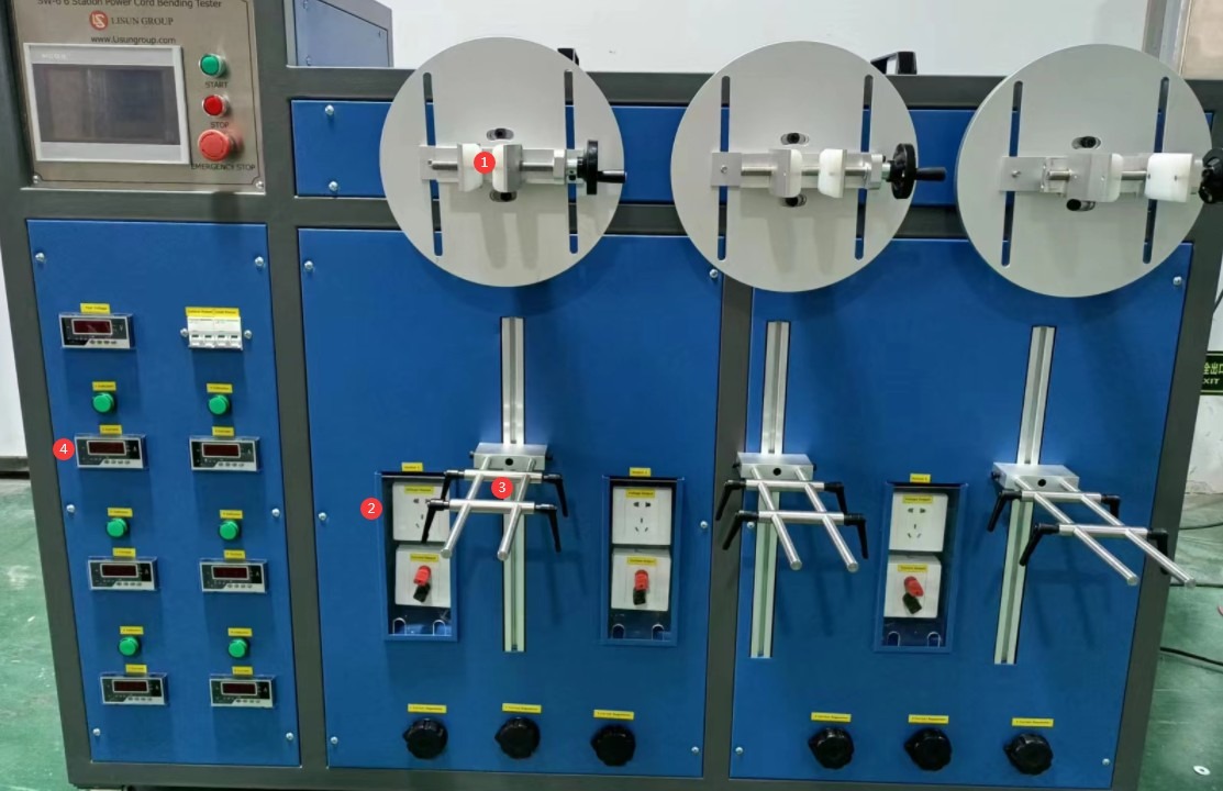
Figure 9
After correctly connecting the device’s power cord and the actual load’s power cord, turn on the device. ④ Turn on the actual load and let it run until it reaches normal operating conditions; the actual current in the power cord will be displayed here.
5.2.2 Test Parameter Settings
Configure the settings as described in Sections 3.2 and 4.1.
5.2.3 Operational Testing
On the “Circuit Detection” page, press the number button corresponding to the workstation to monitor its load current. Reset the count for all workstations to zero.
On the “Test” screen, click “Reset” or “Return to Zero,” then click “Start Test” to begin the test. During the test, you can go to the “Continuity Test” screen to view real-time data from all test stations.
The test stops automatically once the set number of test cycles has been completed, or when no current is detected at any of the loaded test stations.
5.3 Testing Without a Load
5.3.1 Sample Installation and Commissioning
① Clamp the end of the sample power cord to be tested—that is, the end with the insulation—here. ② Attach an appropriate weight to the power cord and thread it through the hole to prevent it from swinging during the test.
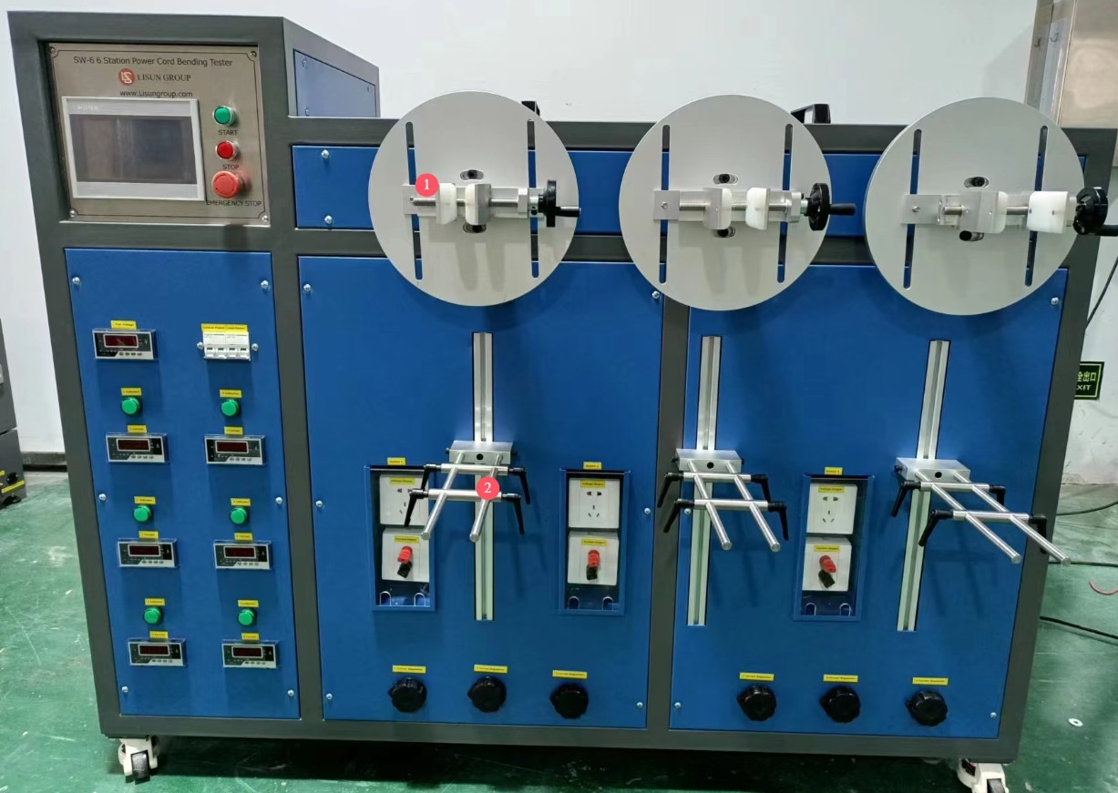
Figure 10
After the device’s power cord is properly connected, turn on the device.
5.3.2 Test Parameter Settings
Configure the settings as described in Sections 3.2 and 4.1.
5.3.3 Operational Testing
On the “On/Off Detection” page, there is no need to monitor the load current. Reset the count for all workstations to zero.
On the “Test” screen, click “Clear” or “Reset,” then click “Start Test” to begin the test.
Once the specified number of tests has been completed, the test stops automatically.
6. Post-Test Procedures
6.1 Test Stopped
6.1.1 Normal Shutdown
Once the device has completed the set number of tests, it will automatically stop running.
6.1.2 Emergency Stop
If any abnormalities occur during the test (such as a specimen falling off, unusual noises from the equipment, or abnormal current), immediately press the emergency stop switch (red button). The equipment will instantly cut off the power supply and stop all movement. After troubleshooting is complete, turn the emergency stop switch clockwise to release it, then restart the equipment.
6.2 Removal and Inspection of Test Specimens
Turn off the device’s power switch, and unplug the device’s power cord and the power cord for the actual load (if used).
Carefully remove the weights, loosen the clamps, and take out the specimen, taking care not to damage the test area of the specimen.
Inspect the test specimens according to the standard requirements: the insulation layer must show no wear or cracks, and broken wires must not have pierced the insulation layer and become exposed; the flexible cable protection device must not be separated from the main body and must show no looseness or damage; the conductor must be free of short circuits or solder defects, and the percentage of broken strands in multi-strand conductors must not exceed 10%; record whether the test specimen meets the standard requirements and document the test results.
7. Daily Maintenance and Care of Equipment
7.1 Daily Maintenance
Cleaning and Maintenance: Wipe down the equipment surface, touchscreen, and fixtures with a dry cloth to remove dust and grease; do not use damp cloths or corrosive cleaning agents.
7.2 Weekly Maintenance
Fixture Inspection: Check that the clamping surfaces of the fixture show no signs of wear or deformation. If the clamping force is insufficient, adjust the fixture’s tightening screws; if there is severe wear, replace the fixture with a spare one.
7.3 Monthly Maintenance
Lubrication of the Drive Mechanism: Turn off the power and unplug the unit. Apply an appropriate amount of lubricating grease to the turntable’s rotating shaft and gear joints to reduce wear and ensure smooth rotation (use high-temperature, anti-aging industrial grease).
7.4 Equipment Storage
7.4.1 Short-Term Storage Requirements
If the equipment is used on a daily basis, no further action is required after cleaning is completed following each test.
7.4.2 Requirements for Long-Term Storage
If the device will not be used for an extended period (more than 1 month), please disconnect all cables and cover the device with a dust cover to prevent dust buildup.
The device should be powered on once a month and left on for half an hour to prevent the aging of electrical components (such as capacitors and contactors).
8. Troubleshooting and Resolution of Common Problems
8.1 The device fails to start
8.1.1 Symptoms of the Malfunction
After pressing the power switch, the device does not respond; the touchscreen does not light up, and the turntable does not rotate.
8.1.2 Possible Causes
Power supply abnormalities (such as a power outage, incorrect voltage, or a damaged outlet); the equipment’s power cord is not properly connected, or there is poor contact between the plug and the outlet; the emergency stop switch has not been released (remains pressed); a blown fuse; or a malfunctioning power switch.
8.1.3 Treatment Methods
Check whether the power supply is functioning normally; test by plugging into a different outlet to confirm that the voltage meets the AC 220 V ±10% requirement; Unplug and replug the device’s power cord to ensure the plug is fully inserted into the outlet and the connection is secure; turn the emergency stop switch clockwise to release it; open the side cover of the device and check if the fuse has blown; replace it with a fuse of the same model (refer to the device nameplate); if the above steps do not resolve the issue, the power switch may be faulty; contact customer service to have the switch replaced.
8.2 Automatic Shutdown of the Equipment During Testing
8.2.1 Symptoms of the Malfunction
After the equipment has been running for a while following startup, it suddenly stops without any alarm or indication of abnormal current.
8.2.2 Possible Causes
During load testing, no current is detected at any of the load stations (e.g., broken test specimen, loose connections); the number of test cycles has reached the preset value (normal shutdown, not a fault); the equipment’s overheat protection has been triggered (prolonged operation under high load); or the emergency stop switch was accidentally activated.
8.2.3 Treatment Methods
For load testing, check whether the test specimen connections at each station are loose or broken. After securing the connections or replacing the specimen, reset the counter to zero and restart the test; Check the total number of cycles displayed on the touchscreen. If the set value has been reached, this constitutes a normal shutdown and no further action is required; if the equipment housing becomes excessively hot, turn off the power, pause the test for 30 minutes, and restart the equipment only after it has cooled down to avoid prolonged, continuous operation under heavy loads; check whether the emergency stop switch was accidentally activated; release the emergency stop switch and then restart the equipment.
8.3 Current Monitoring Anomalies
8.3.1 Symptoms of the Malfunction
During load testing, the current reading is 0, fluctuates excessively, or the device indicates a short circuit (current exceeds twice the rated value).
8.3.2 Possible Causes
During simulated load testing, the L and N terminals of the power cord are not shorted or are poorly shorted; the terminals are loose or oxidized, resulting in excessive contact resistance; the test specimen’s power cord is broken or shorted, or the specimen’s electrical components are faulty; the load current adjustment knob is not set correctly.
8.3.3 Treatment Methods
Check the power cord connections to ensure that the L and N terminals are securely connected with no loose connections; remove the terminal blocks, clean off any oxidation, and retighten the connections to ensure good contact; Check the test sample’s power cord for breaks or short circuits, and replace it with a qualified sample; if conducting a real-load test, verify that the sample’s electrical functions are operating normally; readjust the load current control knob and observe that the current display stabilizes within the set range.
8.4 Abnormal Turntable Rotation
8.4.1 Symptoms of the Malfunction
The turntable rotates jerkily, makes unusual noises, or displays the angle inaccurately.
8.4.2 Possible Causes
The drive mechanism is not properly lubricated, causing wear on the gears and bearings; the turntable mounting screws are loose; and the motor is malfunctioning (e.g., overheating, unusual noises).
8.4.3 Treatment Methods
Turn off the power, apply lubricating grease to the drive mechanism, and check the gears and bearings for wear; replace them if they are severely worn. Tighten the turntable mounting screws to ensure the turntable is securely installed and does not wobble. If the motor overheats or makes unusual noises, stop using it immediately, contact customer service to have the motor inspected, and replace it if necessary.