English
 中文简体
中文简体 English
 Русский
 Español
 Português
 Türkçe
 العربية
 Deutsch
 Polski
 Italiano
 Français
 한국어
한국어 ไทย
ไทย Tiếng Việt
 日本語
日本語





























Compact Goniophotometer
User's Manual
Applicable LISUN models: LSG-1200A
1. Unboxing and Basic Familiarization with the Equipment
1.1 Key Technical Specifications
Complies with IEC, CIE, and LM-79 standards;
Automatic beam angle testing: primary half-intensity angle, as well as 1/2, 3/4, and 1/10 intensity angles, among others, to meet specific requirements;
The test data complies with the IES format and can be used in lighting design software such as Dialux for lighting design;
Comes with a 1-meter-long light box; maximum lamp dimensions: Φ180 mm × 160 mm (diameter × depth);
Test illuminance range: 0.1–30000 cd; probe accuracy: Class A;
Distance between the lamp under test and the probe: 316 mm or 1000 mm;
Angle intervals: Horizontal angles 1°, 5°, 10°, 15°, 22.5°, 30°, 45°, 90°; vertical angles 0.5°, 2°, 1.5°;
Horizontal automatic axis rotation angle (C): 0°–360°; Vertical automatic axis rotation angle (γ): –90°–+90°;
Angular accuracy: ±0.2°.
1.2 Unboxing and Checking the Accessories
1.2.1 Unpacking and Visual Inspection
When unpacking the equipment, handle it gently to avoid scratching the exterior casing with sharp tools. After unpacking, first inspect the exterior of the main unit to ensure there is no visible deformation, dents, or peeling paint, and that the panel gauges and buttons are not damaged or loose. If you discover any damage or deformation to the equipment or its accessories, do not power it on. Please contact us immediately.
1.2.2 Main Unit and Accessories
LSG-1200A Compact Distributed Photometer: 1 unit.
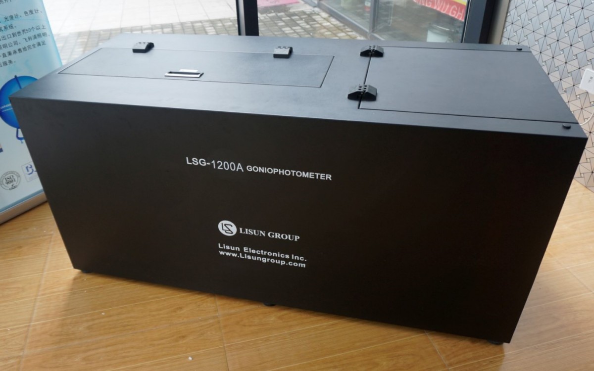
Figure 1
The standard accessories are as follows: ① and ② are used to connect the sample power supply to the device; either one may be used. ③ RS232-USB adapter cable, used to connect the RS232 communication cable to a computer;④ Power cord for the LSG-1200A; ⑤ Power connection cable for connecting the sample; ⑥ RS232 communication cable for connecting the instrument to the RS232-USB adapter; ⑦ Spare fuse.
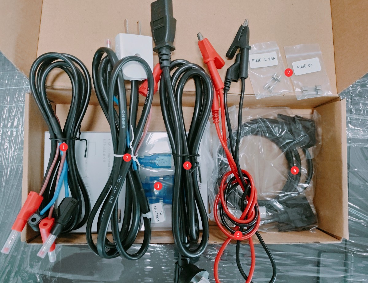
Figure 3
Download links for the digital user manual, warranty card, and other documents have been sent to you via email. Please download them as soon as possible. If you missed the email, you can contact us to request the download links again.
2. Safety Precautions
2.1 Electrical Safety
2.1.1 Power Connection
220V single-phase power; power outlets must comply with safety standards, be properly grounded, and have a rated current that meets the equipment’s power requirements (it is recommended to install a dedicated circuit breaker).
After completing the wiring, pull firmly on the terminal blocks to ensure the connections are secure and there is no looseness.
2.1.2 Grounding Specifications
The equipment must be reliably grounded, with a grounding resistance of ≤4 Ω. Do not use gas pipes, non-metallic water pipes, or the neutral wire as a substitute for the grounding wire. After grounding is complete, use the Grounding Resistance Tester to measure the ground resistance before energizing the equipment. Power may only be applied after confirming that the resistance meets the requirements, to prevent electric shock, equipment malfunction, or measurement errors caused by poor grounding.
2.1.3 Contraindications for the Procedure
Before wiring, inspecting, or maintaining the equipment, you must disconnect the main power supply to the equipment and confirm that there is no residual voltage before proceeding;
Do not operate the equipment’s power switch, touchscreen, or instrument buttons with wet hands to avoid the risk of electric shock;
Do not plug in or unplug power cords or signal cables while the equipment is running, to prevent short circuits that could damage the controller or electrical components.
2.2 Operational Safety
While the equipment is in operation, non-professionals are prohibited from disassembling or repairing it. In the event of a malfunction, contact after-sales service personnel or operate the equipment under the guidance of a technician;
Do not touch rotating parts while the equipment is in operation, as this may result in pinching injuries;
Do not place any foreign objects inside the equipment while it is running, as this may cause damage to the equipment;
In the event of a malfunction or abnormality, immediately stop the test and troubleshoot the problem.
2.3 Place horizontally
The equipment must be placed on a level surface. Use a spirit level to level the equipment: Place the spirit level on the top surface of the equipment and ensure the bubble is centered. Note: The four legs of the equipment are height-adjustable; use them to level the equipment. Once leveled, ensure that all four legs are firmly in contact with the floor.
If the equipment is tilted, it may affect the accuracy of test results and shorten the equipment’s service life.
2.4 Others
For matters not covered in this manual, please proceed with caution or contact us.
3. Connecting the Equipment
① Power switch; ② Equipment power fuse; ③ Power cord socket—please connect to the correct power source according to the label; ④ Connect to a computer using an RS232 cable. If your computer does not have an RS232 port, you can use the RS232-to-USB adapter cable we provide to connect to the computer;⑤ Sample power connection and sample power fuse. If you have purchased our adjustable power supply, connect the power output to this port. If you are using your own power supply, connect it to the correct power source according to the sample’s requirements.
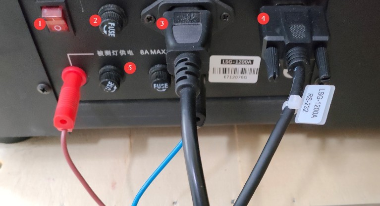
Figure 4
4. Software Installation and Debugging
4.1 Computer Specifications
Compatible with Windows 7, 8, 10, and 11. Requires at least one USB port; there are no other special requirements. Please log in to your computer using an administrator account whenever possible.
4.2 Software Installation and Debugging
4.2.1 Software Installation
Copy all files from the software folder to your computer. ① The driver for the RS232-USB adapter cable; ② The LSG-1200A software installer. Please install all of them directly on your computer.
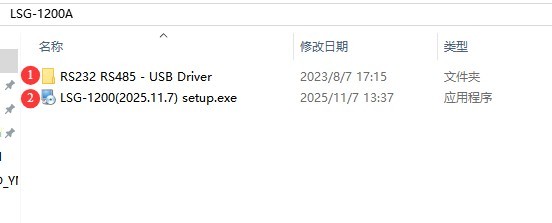
Figure 7
4.2.2 Software Debugging
Turn on the LSG-1200A power supply.
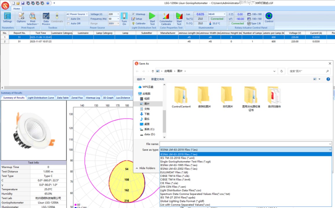
Double-click the software icon on the desktop. The first time you use the software, a window like the one shown below will appear, prompting you to establish communication between the software and the hardware. If communication with the hardware is not established, the software will not function.① The default models for the Goniophotomoeter, near-field photometer probe, and far-field photometer probe are all set to LSG-1200A; no changes are necessary.②If you have purchased our spectrophotometer, AC/DC power supply, or electrical parameter meter, please click the drop-down list on the right to select the corresponding model; otherwise, select “Not Installed” to avoid communication errors. After selecting all correct ③models, click “Auto Search Port,” and the software will automatically search for the correct communication port for each device. If an error message appears, please troubleshoot according to the message; ④click “OK” to save the settings.
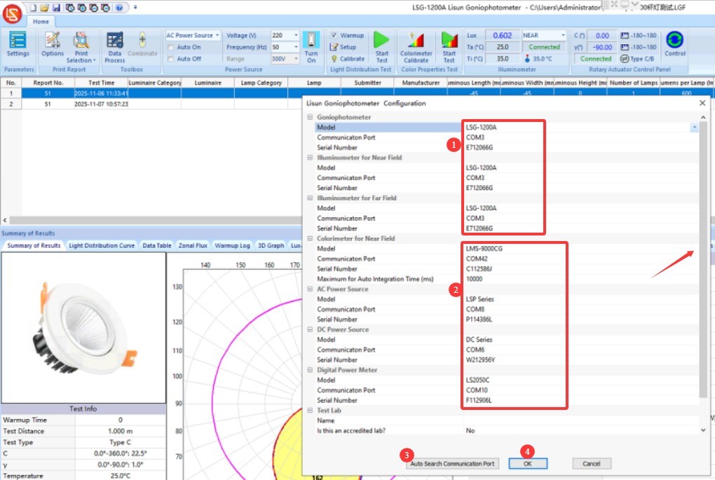
Figure 8
The following window will appear. You will need to create a database file to automatically save test reports. ① Select a path—try to avoid placing it on your desktop; ② Enter a custom file name; ③ After saving, the software will return to the initial screen.
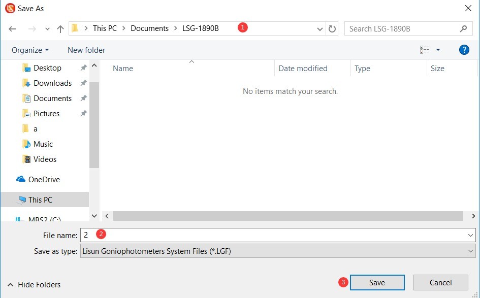
Figure 9
If you would like to create a new database file to save test reports for different products in separate files, please click the white button marked in the image below.
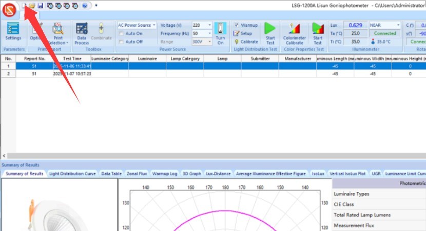
Figure 9.1
Each time you open the software, it will open the database file from your last session by default. If the name or path of the database file has changed since your last session, the software will prompt you to create a new database file.
Note: If you have not purchased our power supply products or spectrometers, the software does not include the following modules.
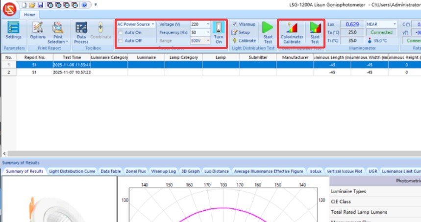
Figure 9.2
4.3 Calibration
The LSG-1200 series goniophotomoeters come equipped with a standard darkroom, eliminating the need for a standard lamp for calibration. The far-field measurement distance is fixed at 1 m, and the near-field measurement distance is fixed at 0.316 m. However, the software includes a calibration function; if you need to perform calibration, you can purchase a standard lamp separately. Otherwise, there is no need to access the following two calibration modules in the software to perform any operations:
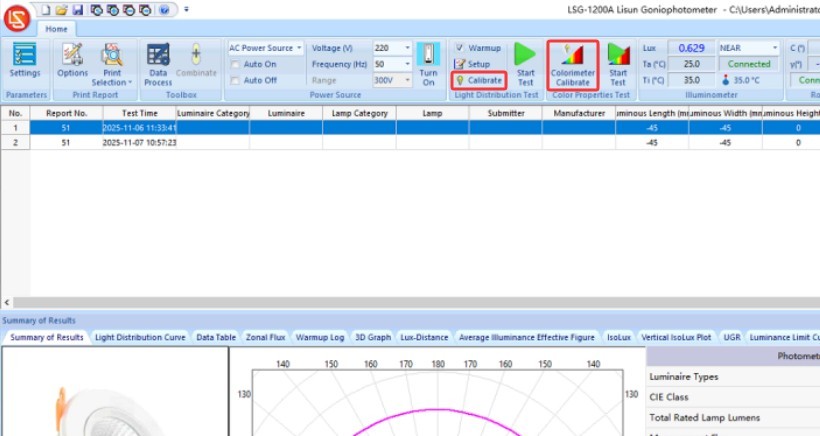
Figure 10
5. Preparations Before Testing
5.1 Test Environment Requirements
Ambient temperature requirements: 23°C ± 2°C, to ensure that the light source’s luminous characteristics and the instrument’s sensor accuracy are not affected by temperature drift;
Relative Humidity Requirements: Relative humidity range: 45%–75% RH, with no condensation; avoid high humidity to prevent short circuits in the instrument’s circuitry and fogging on the light source surface;
Cleanliness: The test area must be free of visible dust and smoke to prevent dust from settling on the surface of the light source or the optical components of the instrument;
Electromagnetic Interference: Stay away from strong electromagnetic fields (such as large electric motors and high-frequency equipment) to prevent interference with the instrument’s signal acquisition;
Vibration and Leveling: The test bench must remain stable and level, with no noticeable vibration (amplitude ≤ 0.1 mm), to prevent mechanical shaking from affecting angular positioning accuracy.
5.2 Sample Installation
Open the right side cover of the LSG-1200A.
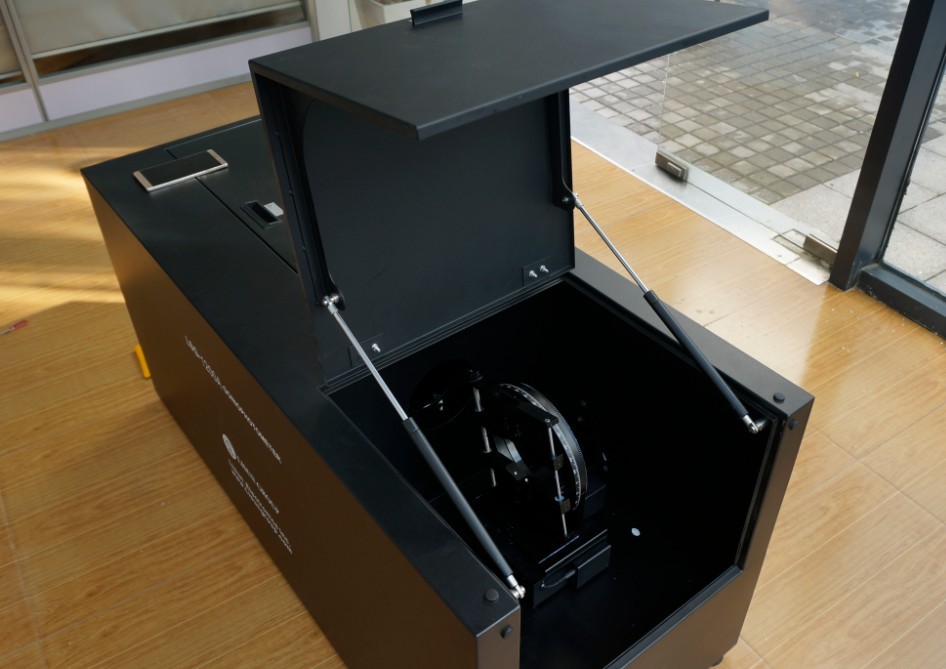
Figure 11
The red and black terminals are used to connect the sample power cables. To ensure safety, be sure to disconnect the sample’s power supply and wear insulated gloves before connecting the sample power cables.
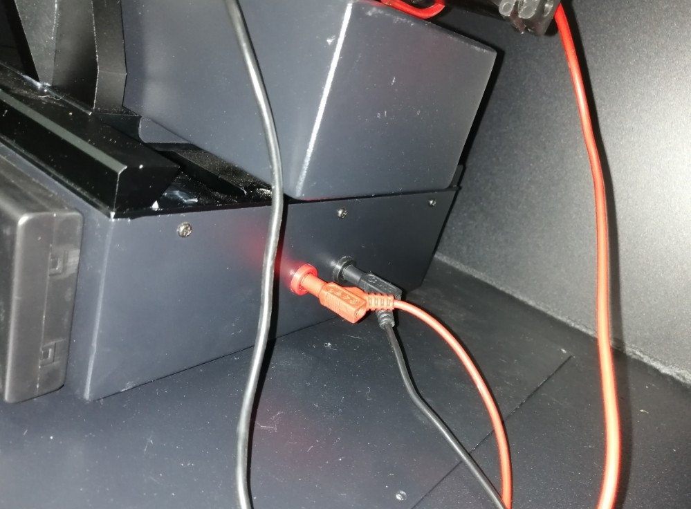
Figure 12
① Single-line laser light box; ② Single-line laser switch; ③ Single-line laser. Please turn on the single-line laser. When installing the sample light fixture, ensure that its light-emitting surface remains vertical and aligned with the single-line laser.
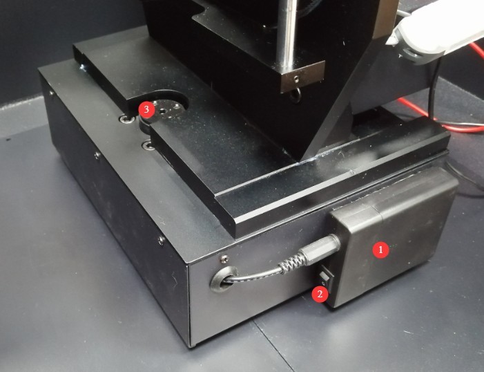
Figure 13
The sample must be secured in the center of the fixture. ① You can adjust the fixture to open or close; ② If the sample or lighting fixture is still not securely held in place after the fixture is closed, use the screw here to secure it.
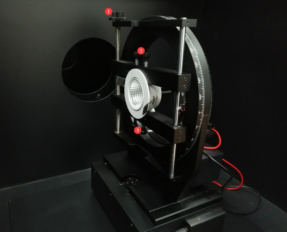
Figure 14
After the sample is secured, turn off the line laser, then close the cover plate.
6. Procedure for Testing Light Intensity Distribution
6.1 Turning on the Lights
If you have purchased our power supply and set it up correctly, the software will include the following modules: ① Select the power supply type (AC or DC) based on the sample; ② Enter the correct parameters, such as voltage and current, based on the sample;③ Select “Auto On” and “Auto Off”; the software will automatically turn on the sample light when the test begins and turn it off when the test ends; ④ If “Auto On” and “Auto Off” are not selected, you can also click “On” or “Off” to control the sample light.
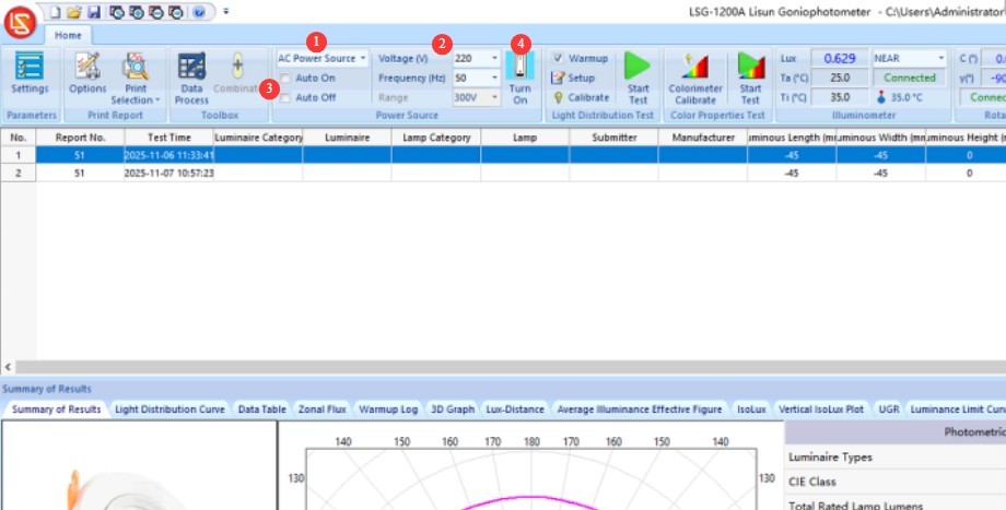
Figure 15
If you did not purchase our power supply and the software does not include the module described above, you will need to manually control the power supply output to turn on the sample lamp.
6.2 Software Settings Before Testing
Click “Settings.” Select the test items you want to display; you can select all of them. Unless you have specific requirements, there is no need to change any other settings.
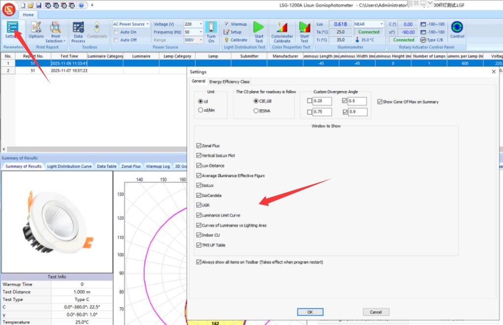
Figure 16
To test for the exact energy efficiency rating, switch to “Energy Efficiency Rating.” Select the desired standard and settings.
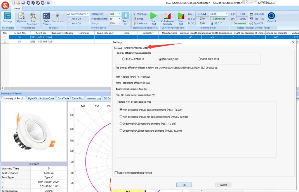
Figure 17
If the luminaire needs to be preheated before formal testing, check the “Preheat” option and go to “Preheat Settings.” ① Select the preheat duration; at least 30 minutes is recommended. ② Set the sampling interval—that is, how often to take a sample during preheating.③ Once the sample lamp has stabilized, you can choose whether to skip the remaining warm-up time as needed; ④ Definition of light source stability; ⑤ Select the parameters to be included in the warm-up curve; ⑥ After configuring the settings, click OK to save.
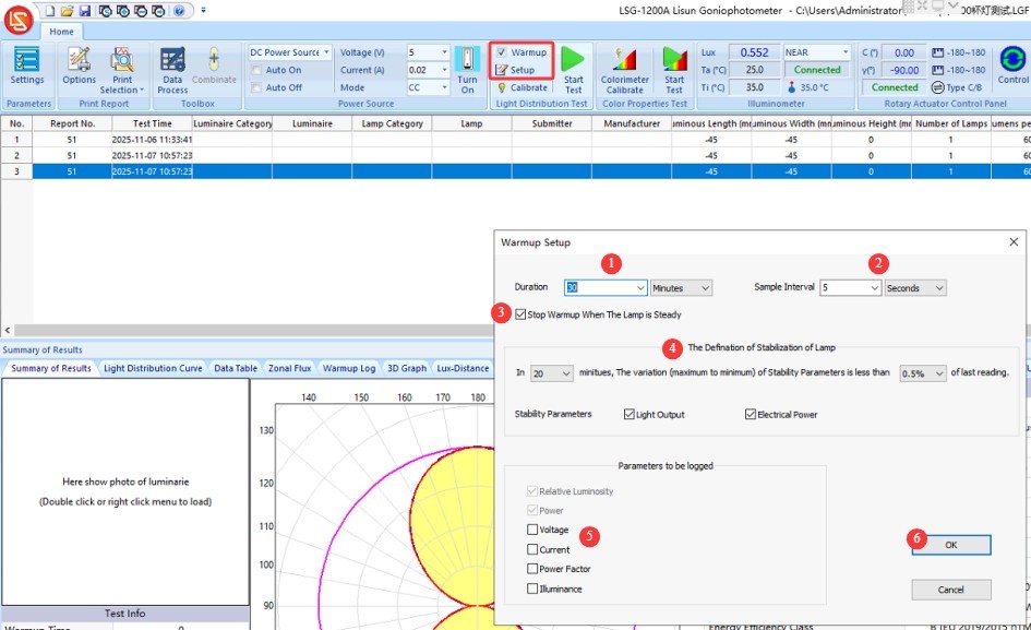
Figure 18
The parameter change curves for the entire preheating process are automatically saved in the test report.
6.3 Test Parameter Settings
Click “Test” to enter the test parameter settings interface. ① C-plane angle settings. The start and end angles (0 to 180) do not need to be modified. The interval angle can be set as needed; the smaller the interval angle, the more accurate the test report will be, but the test will take longer. It is recommended to select a value between 5 and 30. ② G-plane angle settings. The LSG-1200A has a start-to-end angle range of -90 to 90, which does not need to be modified. For the interval angle, unless there are special requirements, it is recommended to select 1; in luminous intensity distribution testing, the G-plane interval angle does not affect the test duration; ③ Probe Position Selection. By default, the probe is installed in the far field at the factory, so select “Far Field” here. If testing LED packages, for example, the standard requires moving the probe to a distance of 0.316 m; in this case, select “Near Field” for the test;④ Attenuator coefficient: Standard equipment does not require an attenuator, so the default coefficient is 1. If you have purchased an attenuator separately, enter the coefficient marked on the attenuator after installation; ⑤ Warm-up position: The default is (0, 0), meaning data is monitored directly in front of the sample luminaire during warm-up;⑥ Normalization: Select “Maximum”; this does not affect the test results; ⑦ Straylight removal function: If you enter 45, this means that only data within the range of -45 to 45 degrees in the G-angle will be considered valid test data, while all other angles will automatically be set to 0. You may enable or disable this function as needed;⑧ Rated luminous flux of the light source: If unknown, leave this field blank; it does not affect the test results; ⑨ Please enter the dimensions of the light-emitting surface correctly; this parameter affects the UGR test results; ⑩ You may enter relevant information about the sample luminaire; ⑪ Enter the temperature and humidity of the current test environment; ⑫ Click OK.
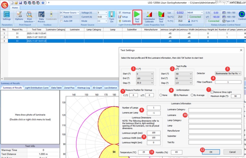
Figure 19
If “Warm-up” is checked, the software will automatically enter the warm-up screen, where you can view the current warm-up status and progress in the upper-right corner.
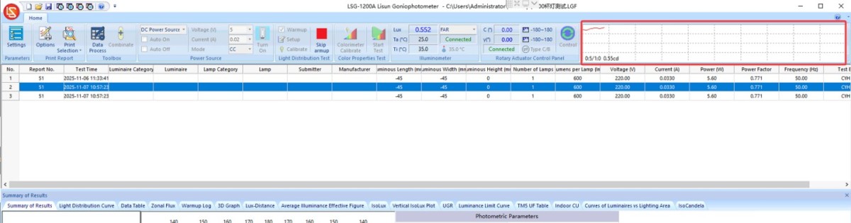
Figure 20
Once the warm-up is complete, proceed to the test interface.
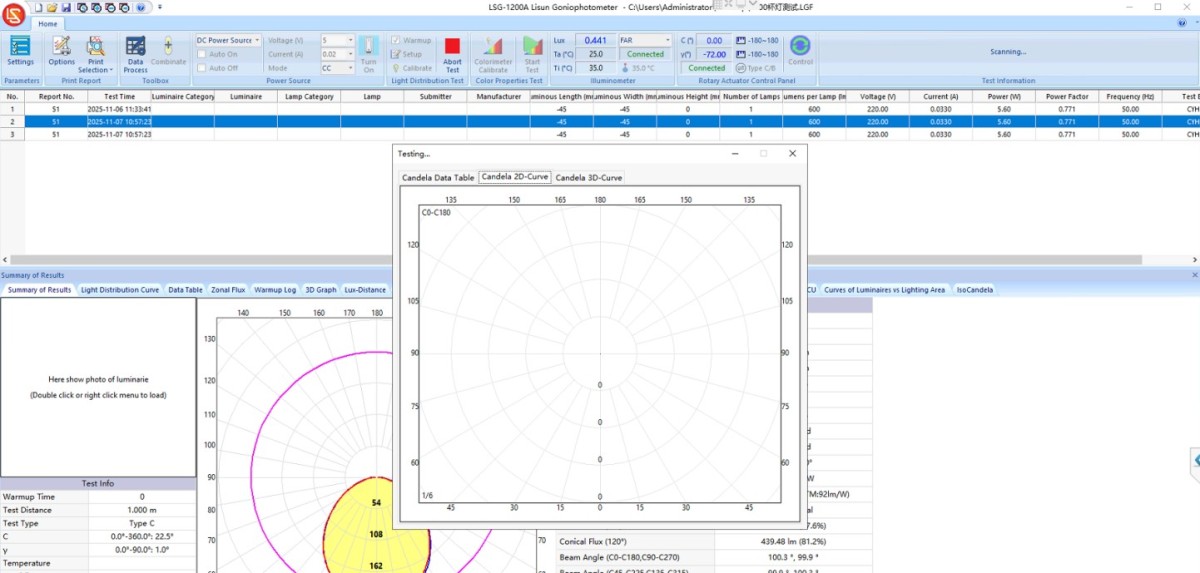
Figure 21
After the test is complete, ① the test report will be automatically saved in the current database file; the path and name of the current database file are displayed at the top of the software; ② the test reports will be automatically saved in this list in chronological order.
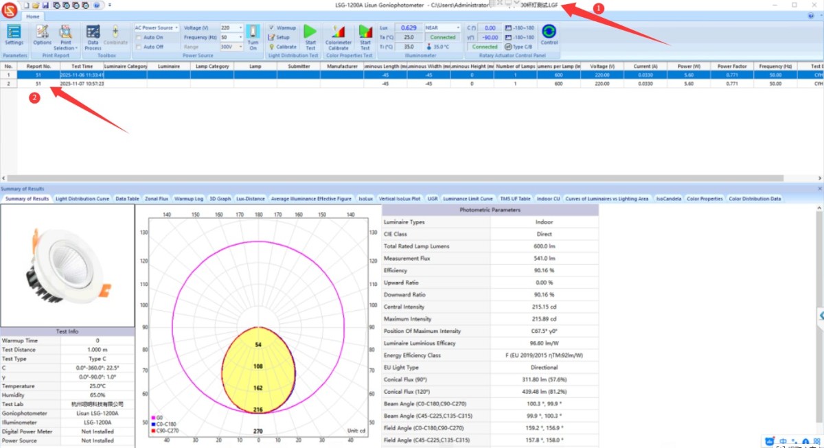
Figure 22
7. End the test
7.1 Equipment Operation
Turn off the power to the sample, put on insulated gloves, remove the sample, and prepare for the next test.
7.2 Processing of Test Reports
① Double-click or right-click here to import a luminaire image; ② Double-click the content in this area to edit it; ③ For all items in the test report, click the corresponding tab to switch between display options.
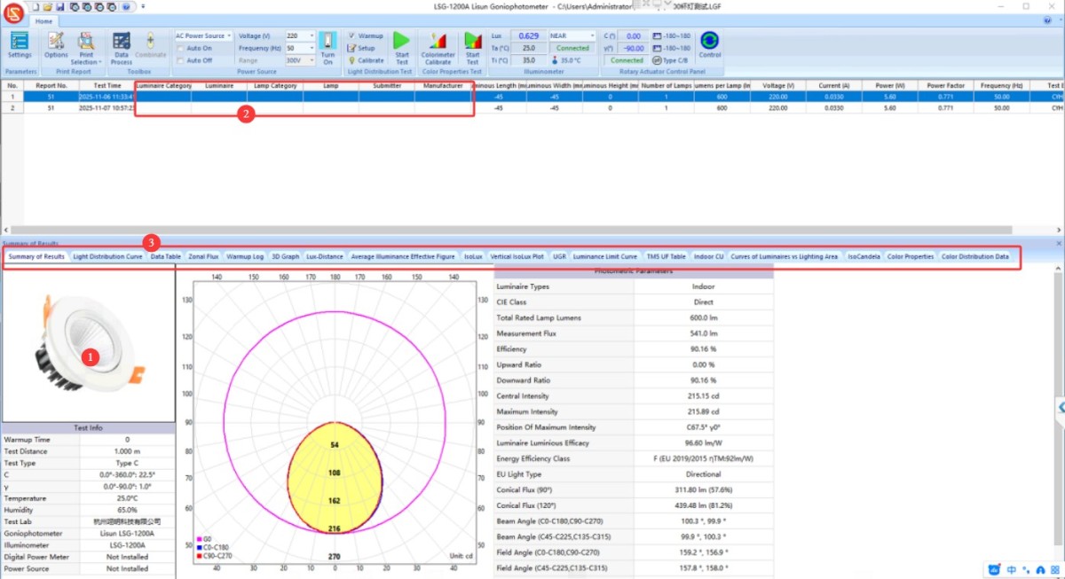
Figure 27
Each tab may display some settings options in the upper-left corner of the screen to adjust the display style and data.
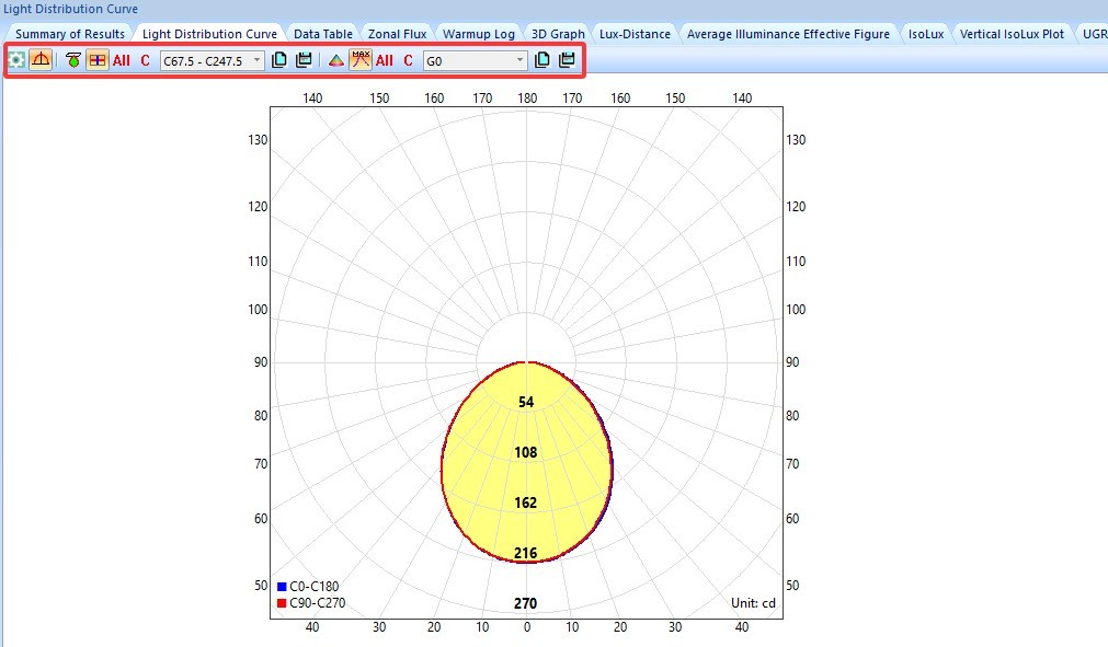
Figure 28
7.3 Print Test Reports and Export Files in Other Formats
7.3.1 Printing the Test Report
Click the “Print” option to configure the print settings for the test report.
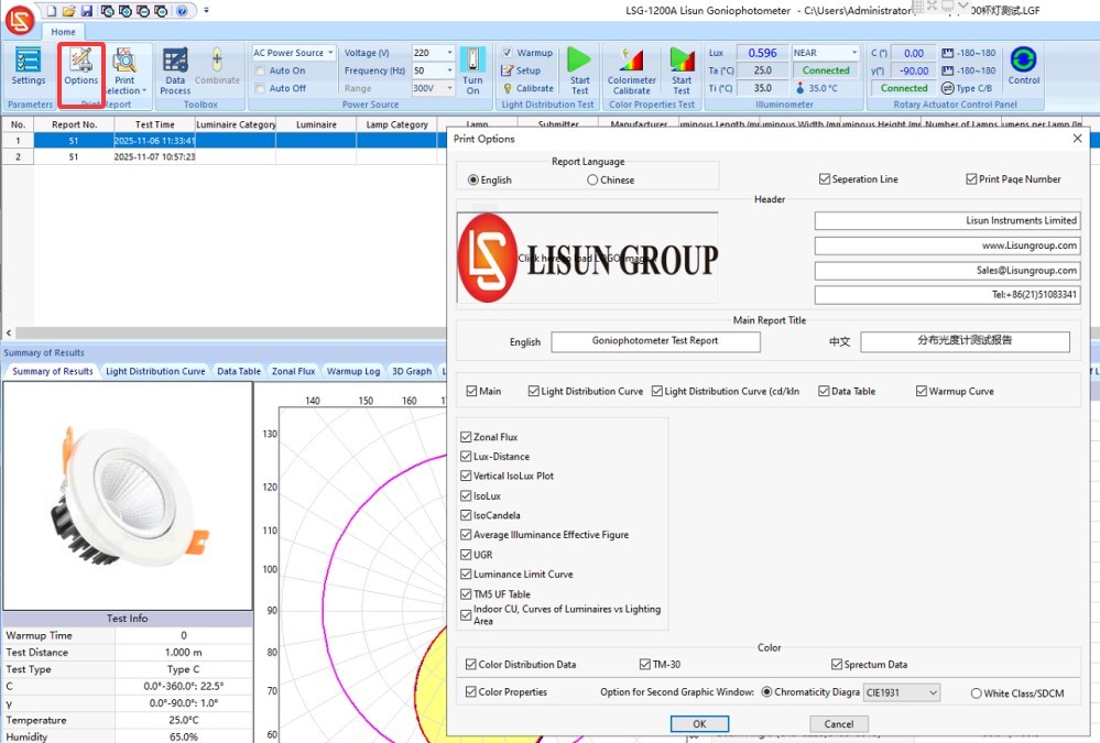
Figure 29
Then click “Print” to save the test report as a PDF (your computer must have a PDF printer installed) or print it on paper (your computer must be connected to a printer).
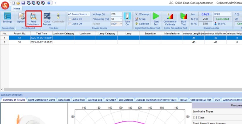
Figure 30
7.3.2 Exporting Files in Other Formats
Click the red LISUN logo in the upper-left corner and select “Export File”:
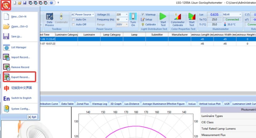
Figure 31
Select the desired file format—such as IES or LDT—and then export it.
Figure 32
8. Daily Maintenance and Care of Equipment
8.1 Short-Term Storage Requirements
If the equipment is used on a daily basis, simply shut it down and clean both the interior and exterior of the unit at the end of the day; no further action is required.
8.2 Long-Term Storage Requirements
If the device will not be used for an extended period (more than 1 month), please disconnect all power cords and other cables and cover it with a dust cover to prevent dust from entering.
The equipment should be powered on once a month; leaving it on for half an hour is sufficient to prevent the aging of electrical components (such as capacitors and contactors).
9. Troubleshooting and Resolving Common Problems
9.1 Communication Errors
Possible causes: The device is not turned on; the USB cable is not connected; drivers are not installed; the wrong model was selected during software configuration; the COM port has been changed.
Solution: Turn on all devices; try a different USB port, and do not use any extension cables or adapters; reinstall the drivers; go back into the software settings, select the correct device model, and run an automatic port scan again.
9.2 Abnormal Test Results
Possible causes: The sample lamp is not lighting up properly, the sample lamp is flickering, the wrong probe was selected, the test distance is abnormal, or the angle interval settings are inappropriate.
Solution: Turn on the sample lamp as usual and allow it to warm up until it reaches a stable state before testing; during testing, ensure the correct probe is selected: select “far field” when the probe is positioned at 1 m, and select “near field” when the probe is positioned at 0.316 m; Enter the calibration interface and verify that the test distance is still correct—1 m for far-field and 0.316 m for near-field; refer to Section 6.1.3 to reset the minimum angular interval and perform the test.
9.3 The turntable cannot be rotated to the specified angle
Possible causes: The turntable is blocked by debris; motor malfunction.
Solution: Shut down the machine and check the area around the turntable for any debris that might be obstructing its rotation; if the motor is malfunctioning, please contact us.
9.4 Power Supply Abnormalities
Symptom: The LSG-1200A fails to power on, or the sample lamp does not light up.
Possible cause: If the power supply is working properly, the fuse may have blown.
Solution: A spare fuse is included in the standard accessories; see section 1.2.2. Then, refer to section 3.1 to check whether the fuse in the corresponding location has blown; if so, simply replace it.
Figure 33