
 English
 中文简体
中文简体 English
 Русский
 Español
 Português
 Türkçe
 العربية
 Deutsch
 Polski
 Italiano
 Français
 한국어
한국어 ไทย
ไทย Tiếng Việt
 日本語
日本語





























Touch Current Measuring Network
User's Manual
Applicable LISUN models: MNTC-G1、MNTC-G2G3、MNTC-G4
1. Basic Understanding of the Product
1.1 Product Overview
1.1.1 Basis for the Standard
The MNTC series contact current test network is a standardized test setup designed in accordance with Appendix G of GB/T 7000.1-2023 (IEC 60598-1:2024), “Luminaires—Part 1: General requirements and tests.” The complete set includes the MNTC-G1, MNTC-G2G3, and MNTC-G4. When used in conjunction, these three devices can measure contact current and protective conductor current in luminaires and various types of electrical equipment, verifying their electrical safety performance under both normal operating and fault conditions.
1.1.2 Core Features
| Product Model Name | Note |
| MNTC-G1 Fault Switching Test Unit | It provides power polarity switching, ground connection control, and neutral connection control for the test circuit, enabling simulated switching between normal operating conditions and various fault conditions; it serves as the core front-end unit for contact current testing. |
| MNTC-G2G3 Human-Weighted Contact Current Network | Integrates the G.2 perception/response-weighted network and the G.3 release-weighted network into a single unit. The two networks separately simulate different physiological effects of electric shock on the human body and output weighted voltage signals for reading by measuring instruments. |
| MNTC-G4 Protective Conductor Current-Weighted Network | Designed specifically for the weighted measurement of high-frequency currents in protective conductors. By simulating the impedance characteristics of the human body, it applies a weighting factor to the high-frequency current components on the protective conductor of Class I luminaires to assess the potential impact of high-frequency currents on the human body. |
1.2 Testing Principles and Application Scenarios
Touch current refers to the current that flows through the human body when a person comes into contact with an accessible part of electrical equipment. This series of test networks uses precision resistors and capacitors to simulate the impedance characteristics of the human body, applies weighted processing to the equipment’s leakage current, and reproduces the physiological response model specified in the standard, thereby quantitatively assessing the level of electric shock risk.
Ex-factory contact current testing for lighting fixture manufacturers; safety performance verification for information technology equipment; electrical safety compliance testing for household appliances; safety certification testing by third-party testing organizations; product sampling inspections by quality supervision authorities; and research on electrical safety standards in laboratories.
1.3 Equipment Verification
1.3.1 Unpacking
When unpacking the device, handle it gently to avoid scratching the casing with sharp tools. After unpacking, first inspect the exterior of the device to ensure there is no visible deformation or dents, and that the buttons are not damaged or loose. If you notice any abnormalities with the device or its accessories, do not turn it on. Please contact us immediately.
1.3.2 Downloading Electronic Documents
Links to the digital user manual, warranty card, calibration certificate, and other documents have been sent via email. If you did not receive the email, please contact us to obtain the links again.
2. Safety Precautions
2.1 Personal Safety
High-Voltage Warning: During testing, the equipment terminals and the enclosure of the device under test may carry dangerous voltages. Operators are strictly prohibited from directly touching live parts.
Insulation Protection: Test personnel must wear insulated shoes, stand on an insulated mat while performing the test, and keep their hands dry.
Power-Off Procedures: When connecting, changing, or replacing test leads, or when replacing the device under test, you must first disconnect the power supply. Under no circumstances should you plug in or unplug test leads while the device is energized.
Working Alone Is Prohibited: During high-voltage testing, it is recommended that at least two people be present—one to operate the equipment and one to supervise—to facilitate power disconnection in case of an emergency.
2.2 Equipment Safety
An Isolation Transformer must be used: The MNTC-G1 must be used in conjunction with an Isolation Transformer. Direct connection to the mains power grid is prohibited to prevent common-mode interference and ground loops from affecting test accuracy, and to ensure electrical isolation between the test circuit and the power grid.
Do Not Exceed Rated Voltage: Supply power strictly in accordance with the equipment’s rated voltage specifications; exceeding the rated voltage is strictly prohibited.
Prevent Short Circuits: Do not allow accidental short circuits between test terminals to avoid damaging the internal precision resistor and capacitor components.
Environmental Requirements: The equipment should be placed in a dry, well-ventilated environment free of corrosive gases, away from sources of strong electromagnetic interference.
2.3 Test Specifications
Before testing, verify that the insulation of the equipment under test is intact and that there are no obvious damages or exposed live parts.
When testing the network, do not reverse the connections between terminals A and B; otherwise, the measurement results will be invalid.
Measuring instruments such as oscilloscopes must be reliably grounded, and the probe gain setting must match the actual conditions.
When conducting fault condition testing, the fault condition should be applied gradually while closely monitoring changes in current to prevent the device under test from overheating and burning out.
3. Product Introduction
3.1 Standard Diagram
3.1.1 MNTC-G1 Fault Switching Test Unit G.1
See Figure 3-1 (taken from IEC 60598-1:2024, Figure G.1).
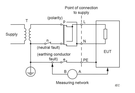
Figure 3-1
3.1.2 MNTC-G2G3 Human-Weighted Contact Current Network G.2 and G.3
See Figures 3-2 and 3-3 (taken from IEC 60598-1:2024, Figures G.2 and G.3).
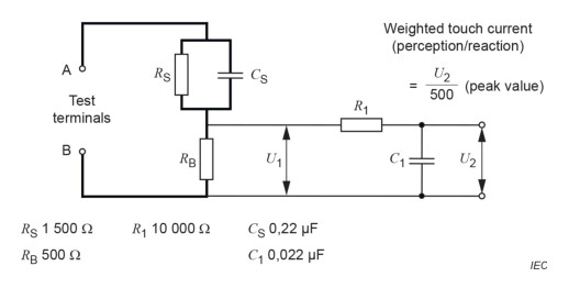
Figure 3-2
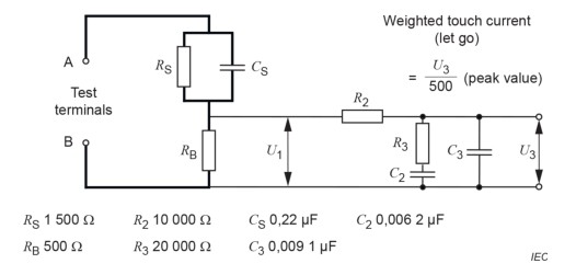
Figure 3-3
3.1.3 MNTC-G4 Protective Conductor Current-Weighted Network G.4
See Figures 3–4 (taken from IEC 60598-1:2024, Figure G.4).
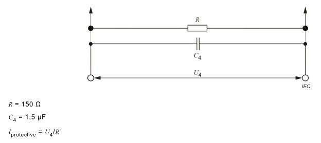
Figure 3-4
3.2 Actual Photo
3.2.1 MNTC-G1 Failover Test Unit G.1
See Figures 3–5.
| Number | Note |
| ① | The power connector is on the left, as shown in Figure 3-6. |
| ② | The interfaces of the test device are shown on the right, as shown in Figure 3-7. |
| ③ | Neutral Conductor Fault |
| ④ | Polarity |
| ⑤ | Grounding Conductor Fault |
| ⑥ | Ground Terminal |
| ⑦ | Measuring Network Connection Terminals |
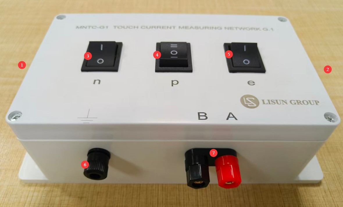
Figure 3-5
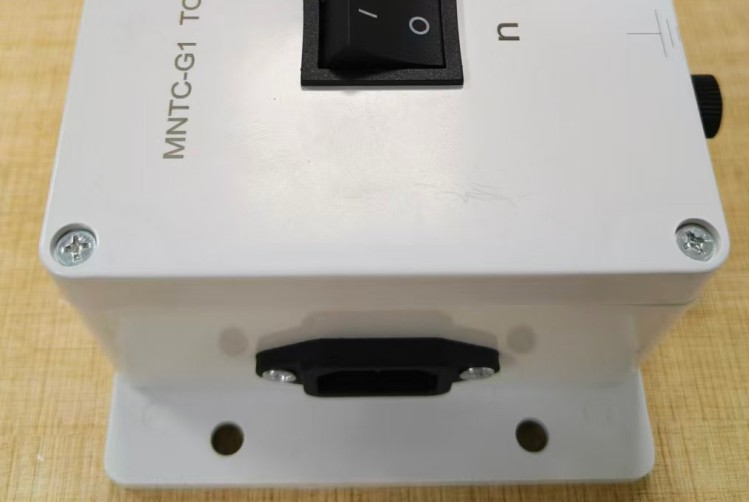
Figure 3-6
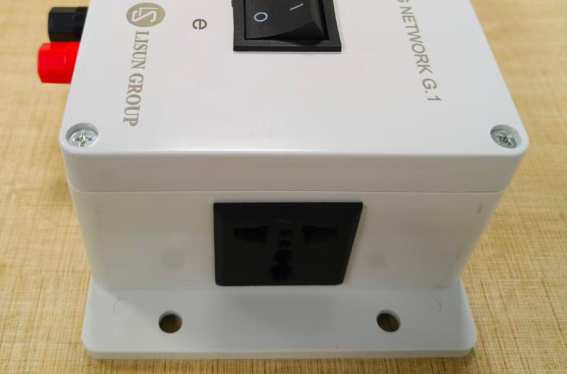
Figure 3-7
3.2.2 MNTC-G2G3 Body-Weighted Contact Current Network G.2 and G.3
See Figures 3–8.
| Number | Note |
| ① | Test Terminals |
| ② | Voltage U1 Measurement Terminal |
| ③ | U2/U3 Switch |
| ④ | Voltage U2 Measurement Terminal |
| ⑤ | Voltage U3 Measurement Terminal |
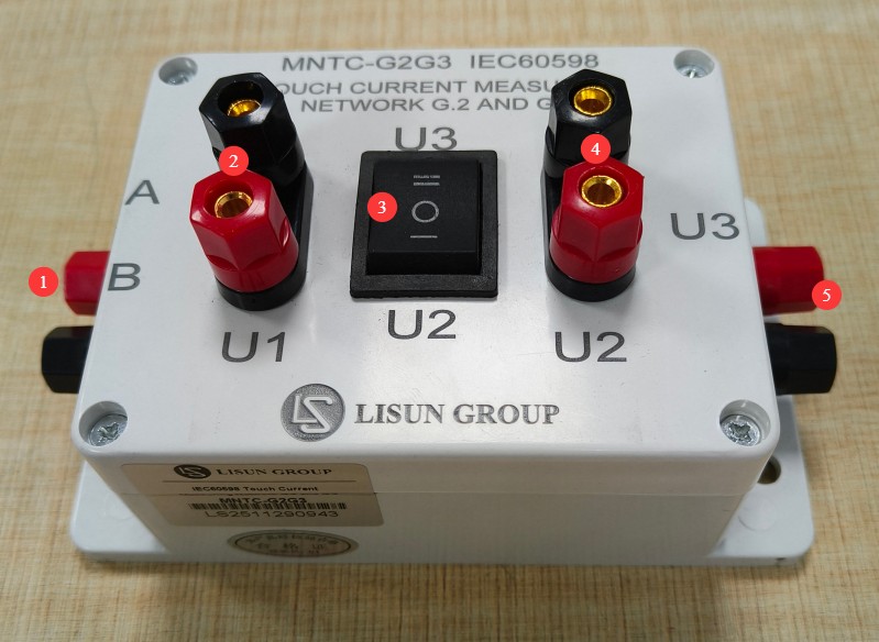
Figure 3-8
3.2.3 MNTC-G4 Protective Conductor Current-Weighted Network G.4
See Figure 3-9.
| Number | Note |
| ① | Test Terminals |
| ② | Voltage U4 Measurement Terminal |
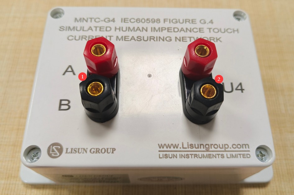
Figure 3-9
4. Preparations Before Use
4.1 Preparation of Instruments and Equipment
| Equipment Name | Specification Requirements | Uses |
| Isolation Transformer | Capacity ≥ rated power of the device under test; isolated output | Provide an isolated power supply for the test circuit |
| Regulated Power Supply (Optional) | 0–250 V adjustable, 50/60 Hz | Provides the rated voltage and 1.06 times the rated voltage |
| Digital Oscilloscope | G.2/G.3: Power-frequency contact current ≥ 1 MHz; G.4: High-frequency protective conductor current; oscilloscope bandwidth ≥ 10 MHz; Voltage Probe ×1/×10 | Read the voltage waveforms and peak values of U₁, U₂, U₃, and U₄ |
| Digital Multimeter | True RMS type, frequency response ≥ 1 kHz | Measure the RMS voltage and verify the power supply voltage |
| Test Leads | High-Voltage Insulated Type, Banana Plug / Spade Connector | Connections Between Equipment and Connections to the Device Under Test |
| Metal Foil Electrodes | 10 cm × 20 cm foil without adhesive backing | Touch the accessible surfaces of the device under test |
| Insulation Test Stand | Insulation resistance ≥ 100 MΩ | Place the device under test |
| Insulated Mat | Thickness ≥ 3 mm; power-frequency withstand voltage ≥ 10 kV | Protection for Standing Operators |
4.2 Verification of Environmental Conditions
Ambient temperature: 15°C to 35°C; Relative humidity: 45% to 75%, no condensation; Atmospheric pressure: 86 kPa to 106 kPa; No strong electromagnetic interference in the vicinity, and no direct sunlight; The test bench must be located at least 0.5 m away from grounded metal components.
4.3 Preparation of the Device Under Test
The device under test (DUT) is in good physical condition with no visible damage to the insulation; verify the DUT’s rated voltage, rated power, and protection class (Class I / Class II); Clean the accessible metal surfaces of the DUT, removing oil and oxidation; for Class I equipment, verify that the grounding terminal is intact; for Class II equipment, verify that there are no exposed grounding parts; place the DUT in the center of the insulation test bench, leaving a safe operating distance around it.
5. Product Usage Instructions
5.1 System Wiring Procedure
5.1.1 Connecting the Isolated Power Supply
Connect the input of the Isolation Transformer to the utility power grid; connect the output of the Isolation Transformer to the power input terminal of the MNTC-G1; verify that the secondary neutral point of the Isolation Transformer is not grounded (floating).
5.1.2 Testing the Network Connection
Reliably connect the A and B terminals of the MNTC-G1 to the A and B terminals of the MNTC-G2 and G3 using test leads; if testing the protective conductor current, connect the corresponding terminal of the MNTC-G4 to the test circuit; all connections must be made with the power off.
5.1.3 Connecting the Device Under Test
Plug the power cord of the device under test into the DUT output receptacle on the MNTC-G1; for Class I devices, connect the MNTC-G1’s ground terminal to an accessible metal part of the device under test using a test lead (or metal foil electrode); verify that all connections are secure and that there are no exposed live parts.
5.1.4 Connecting the Measuring Instrument
Ensure the oscilloscope is reliably grounded; connect the oscilloscope’s Voltage Probes to the measurement outputs (U₁, U₂, U₃, or U₄) of the test network; set the probe gain to match the actual value (typically ×10); adjust the oscilloscope’s vertical and time base settings so that the waveform is easy to observe.
5.2 Contact Current Test Under Normal Operating Conditions
5.2.1 Applicable Networks
G.2 (Perception/Reaction Weighting) or G.3 (Escape Weighting; applicable only to Class I two-plug fixtures).
5.2.2 Procedure
| Instructions | Note |
| ① | Set the polarity switch on the MNTC-G1 to the “positive phase” position, set the grounding switch to “ON,” and set the neutral switch to “ON.” |
| ② | Turn on the Isolation Transformer’s power supply and slowly adjust the voltage to the rated voltage of the device under test. |
| ③ | Wait until the device under test has reached a stable operating state (the luminaire has reached a stable light output, typically after at least 15 minutes) |
| ④ | Observe the waveform on the oscilloscope, and once the waveform has stabilized, read the peak value of U₂ (Network G.2) or U₃ (Network G.3). |
| ⑤ | Calculate the contact current using the following formula: I_touch = U_peak / 500Ω |
| ⑥ | Set the polarity switch to the “Reverse” position, repeat the measurement described above, and record the maximum value. |
| ⑦ | After testing is complete, first reset the regulated power supply to zero, then turn off the power switch. |
5.3 Contact Current Testing Under Fault Conditions
In accordance with the standard requirements, tests must be conducted separately to simulate single or combined fault conditions.
Note: When testing under fault conditions, closely monitor the status of the device under test. If any abnormalities occur—such as smoke, unusual noises, or a burning smell—immediately shut off the power and stop the test.
5.3.1 Fault 1: Protective Grounding Disconnected
| Instructions | Note |
| ① | Set the MNTC-G1 grounding switch to the “Off” position |
| ② | Maintain the rated voltage supply, and once the system has stabilized, read and record the peak current. |
| ③ | Measure once in the forward direction and once in the reverse direction, then take the maximum value. |
5.3.2 Fault 2: Neutral Line Break
| Instructions | Note |
| ① | Set the center-line switch on the MNTC-G1 to the “Off” position. |
| ② | Maintain the rated voltage supply, and once the system has stabilized, read and record the peak current. |
| ③ | Measure once in the forward direction and once in the reverse direction, and take the maximum value. |
5.3.3 Fault 3: 1.06 times the rated voltage
| Instructions | Note |
| ① | Adjust the power supply voltage to 1.06 times the rated voltage |
| ② | Test under both normal grounding and disconnected grounding conditions |
| ③ | Measure once in the forward direction and once in the reverse direction, and take the maximum value. |
5.4 Protective Conductor Current Test (G.4 Network)
| Instructions | Note |
| ① | Connect the MNTC-G4 to the test circuit |
| ② | The device under test operates normally at the rated voltage. |
| ③ | Measure the G.4 network output voltage using an oscilloscope or a true RMS multimeter |
| ④ | Calculate the weighted protective conductor current using the standard formula |
| ⑤ | Test under both in-phase and out-of-phase conditions, and take the maximum value. |
| ⑥ | Determine whether it meets the standard by comparing it to the limit values |
5.5 Interpretation of Test Results
Determinations shall be made in accordance with the GB/T 7000.1-2023 (IEC 60598-1:2024) standard.
Touch Current (Peak): Class II luminaires and portable Class I luminaires with non-grounded plugs ≤ 0.7 mA
Protective conductor current (root mean square value): When the rated current is ≤4 A, ≤2 mA; when 4 A < rated current ≤10 A, ≤0.5 mA/A; when the rated current is >10 A, ≤5 mA.
The maximum value among all test conditions is used as the basis for the final determination; the test is considered pass if the maximum value does not exceed the limit.
5.6 Post-Test Procedures
Set the output voltage of the regulated power supply to zero; turn off the Isolation Transformer’s power switch; fully discharge high-capacitance devices under test; first disconnect the cables on the device side, then disconnect the cables within the test network; turn off measurement instruments such as the oscilloscope; organize the test leads and return the equipment to its designated storage location.
6. Routine Maintenance and Care
6.1 Daily Cleaning
Wipe the equipment housing with a dry, soft cloth to remove surface dust; gently wipe the terminals with a cotton swab dipped in anhydrous alcohol to remove oxidation; be sure to disconnect the power before cleaning, and do not allow liquids to enter the interior of the equipment; do not use corrosive cleaning agents or organic solvents for cleaning.
6.2 Storage Requirements
Storage temperature: -10°C to +55°C; relative humidity: ≤80%, no condensation; avoid heavy pressure, impacts, and drops; keep away from strong magnetic fields, strong electric fields, and corrosive gases; before long-term storage, clean the equipment, place desiccant inside, and store it in a dry, well-ventilated area.
6.3 Calibration Interval Requirements
To ensure the measurement accuracy and operational reliability of the equipment, it is recommended that it be sent periodically to a qualified third-party metrology laboratory for calibration. The recommended calibration interval is 12 months. Users may determine the specific calibration interval based on frequency of use, environmental conditions, and quality system requirements.
7. Troubleshooting and Resolving Common Problems
| Fault Symptoms | Possible Causes | Procedure |
| The oscilloscope does not display a waveform, and the reading is zero. | Wiring break or poor connection | 1. Check whether the test leads in each section are conductive . 2. Check whether the terminals are tightened . 3. Verify that the device under test is properly powered . 4. Check whether the oscilloscope probes are damaged. |
| The test values are significantly lower than expected. | Incorrect probe magnification setting or incorrect network selection | 1. Verify that the oscilloscope probe gain matches the panel settings. 2. Confirm that you are connected to the correct test network . 3. Check whether the device under test is functioning properly. |
| The test results are significantly higher than expected, far exceeding the limit. | Insulation failure or wiring error in the device under test | 1. First, turn off the power and check whether the insulation of the device under test meets the requirements . 2. Verify that the A and B terminals are not reversed . 3. Check the test leads for a short to ground. 4. Verify that the Isolation Transformer is providing proper isolation. |
| Readings fluctuate widely and are unstable | Electromagnetic interference or a loose connection | 1. Keep the device away from strong sources of interference, such as inverters and motors. 2. Check that the metal foil is in close contact with the device under test. 3. Set the oscilloscope to average sampling mode . 4. Check that the ground connection is secure. |
| The test results for the positive and negative controls showed significant differences. | Asymmetry in the capacitance of the device under test (Y) or a ground fault is present | 1. This is normal; use the higher value as the basis for judgment. 2 . If the difference exceeds one order of magnitude, check the internal wiring of the device under test. |
| Abnormal Results in High-Frequency Component Testing | G.4 Network Frequency Response Deviation or Poor Contact | 1. Check that the G.4 network terminal connections are secure . 2. Verify that the oscilloscope’s bandwidth meets the requirements . 3. Send the device to a metrology laboratory for calibration of high-frequency parameters. |
| The equipment enclosure has inductance | Poor Grounding or Isolation Failure | 1. Immediately turn off the power and stop using the equipment . 2. Check whether the Isolation Transformer is operating normally. 3. Check the interior of the equipment for any insulation damage. |
| The terminals are getting hot and there is a burning smell | Excessive current or loose terminals | 1. Immediately turn off the power . 2. Check whether the device under test has a short circuit . 3. Tighten the terminal screws . 4. Verify that the test current does not exceed the device’s rated capacity. |