
 English
 中文简体
中文简体 English
 Русский
 Español
 Português
 Türkçe
 العربية
 Deutsch
 Polski
 Italiano
 Français
 한국어
한국어 ไทย
ไทย Tiếng Việt
 日本語
日本語





























Integrating Sphere
User's Manual
Applicable LISUN models: IS-*M、IS-*MA、IS-*MA**C
1. Basic Understanding of Equipment
1.1 Key Technical Specifications
1.1.1 Parameters and Notes
| Parameters | Note |
| Inner Wall Coating | The primary raw material is BaSO₄ (barium sulfate), which meets the requirements of standards such as CIE Pub. No. 84 (1989) and IES-LM-79. |
| Spectral Reflectance | 450 nm–800 nm: ρ(λ) ≥ 0.96; 380 nm–450 nm: ρ(λ) ≥ 0.92 |
1.1.2 Model Numbers and Descriptions
| Model | Note |
| IS-*M | Small Integrating Sphere; * indicates the diameter of the Integrating Sphere; standard sizes include 0.3 m and 0.5 m |
| IS-*MA | Integrating Sphere with a test platform; * denotes the diameter of the Integrating Sphere; standard sizes include 1 m, 1.5 m, 1.75 m, 2 m, 2.5 m, and 3 m. |
| IS-*MA**C | Integrating Sphere with a circular aperture on the side and a load platform; * denotes the diameter of the Integrating Sphere (standard sizes as above); ** denotes the side aperture dimensions. Example: 33C refers to a 300-mm-diameter circular side aperture. |
| IS-*MA**P | Integrating Sphere with a load platform and a square-hole side opening; * indicates the diameter of the Integrating Sphere (standard dimensions as above); ** indicates the dimensions of the side opening. For example, 33P refers to a square-hole side opening with a length and width of 300 mm. |
Note: Other sizes and features are available upon request.
1.2 Verification of Equipment Configuration
1.2.1 Unpacking
When unpacking the device, handle it gently to avoid scratching the outer casing with sharp tools. After unpacking, first inspect the exterior of the device to ensure that the sphere is closed and that there are no visible deformations or dents. If you notice any abnormalities with the device or its accessories, please contact us immediately.
1.2.2 Main Unit and Accessories
| Model | Note |
| IS-*M | The IS-0.3M includes an MR16 lamp holder, while the IS-0.5M includes an E27 lamp holder and an E27-to-MR16 adapter. |
| IS-*MA | Includes a mounting platform (with an E27 lamp holder), an E27-to-MR16 adapter, and an auxiliary light fixture; the Integrating Sphere, with a diameter of at least 1.5 m, also includes a cross-laser assembly and a strip light fixture. |
| IS-*MA**C | Based on the IS-*MA design, the circular side opening on the right hemisphere is removable. |
| IS-*MA**P | Based on the IS-*MA design, the square side opening on the right hemisphere is removable. |
Note: All Integrating Sphères include four standard-size connectors for connecting to spectrophotometer Optical Fibers, photometric probes, temperature probes, and other devices. Connector sizes can be customized.
1.2.3 Downloading Electronic Documents
We have already sent the download links for the digital user manual, warranty card, and other documents via email at the time of shipment. Please download them promptly. If you missed the email, you can contact us to request the download links again.
2. Precautions for Use
2.1 Key Contraindications Before the Procedure
2.1.1 Contraindications for Coating Protection
Do not allow any materials—including bare hands, cloths, or paper towels—to come into contact with the inner wall coating; do not allow liquids, oil, or dust to enter the ball;
Once the coating is extensively contaminated, it is nearly impossible to restore; do not attempt to wipe or sand it yourself.
2.1.2 Operational Contraindications for Personnel
Clean white cotton gloves must be worn when working inside the ball; tools with dust or grease on them are prohibited from being brought inside the ball; do not forcefully pull or tug on the ball’s opening and closing mechanisms, connectors, or wiring.
2.2 Code of Conduct During Operations
2.2.1 Internal Operating Procedures
Handle samples with care when installing or removing them; do not touch the inner wall of the sphere. Samples must be securely fastened to prevent them from falling and damaging the coating. When connecting wires, touch only the insulation and do not pull on the wire core.
2.2.2 Test Environment Specifications
Use in a dust-free, vibration-free environment; place on a sturdy, level surface to prevent movement or shaking;
Avoid direct sunlight; ambient temperature: 25±2°C, relative humidity ≤70% RH.
3. Assembly and Calibration of The Integrating Sphere
3.1 Stage Installation and Connection (No stage for diameters less than 1 m)
3.1.1 Stage Installation
To prevent the large Integrating Sphere from opening during shipping, we secure it with screws. Please remove the two screws holding the Integrating Sphere in place. Then open the Integrating Sphere and make sure the right hemisphere opens and closes smoothly.
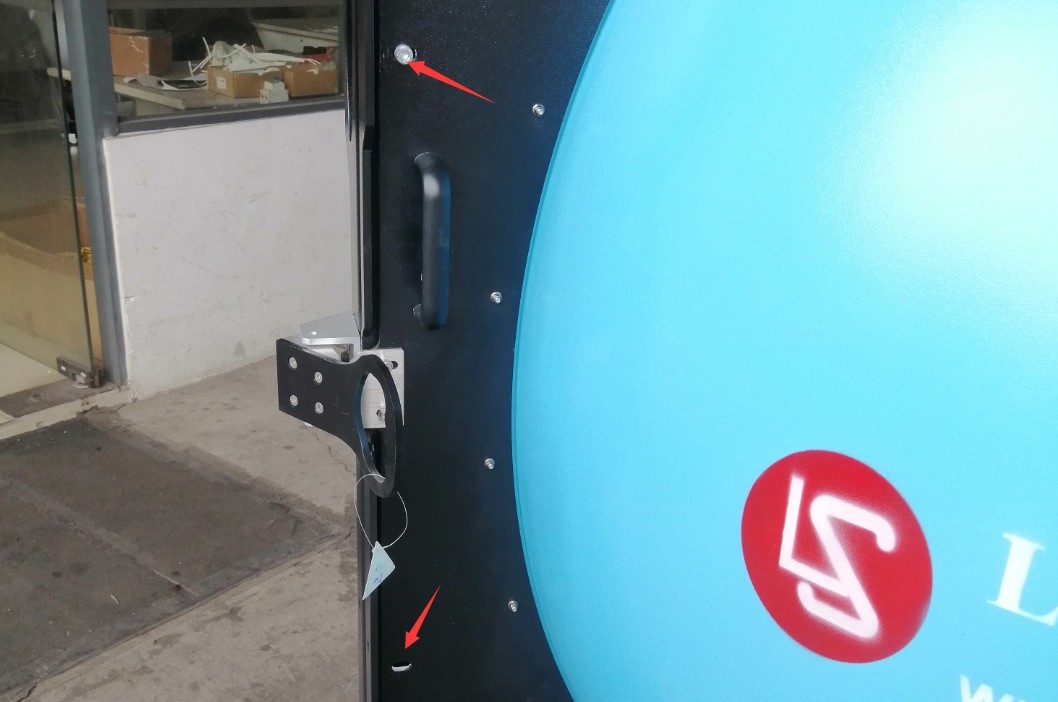
Figure 1
The stage can be mounted either on top of the Integrating Sphere or at the bottom. Here, we’ll use the example of mounting the stage at the bottom. Open the large Integrating Sphere, loosen this screw, and remove the plug.
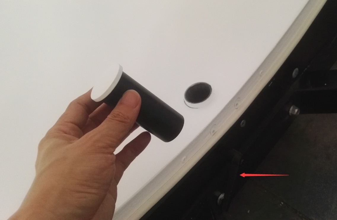
Figure 2
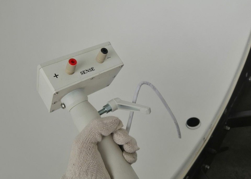
Figure 3
Then retighten the screw, making sure the screw head is facing downward.
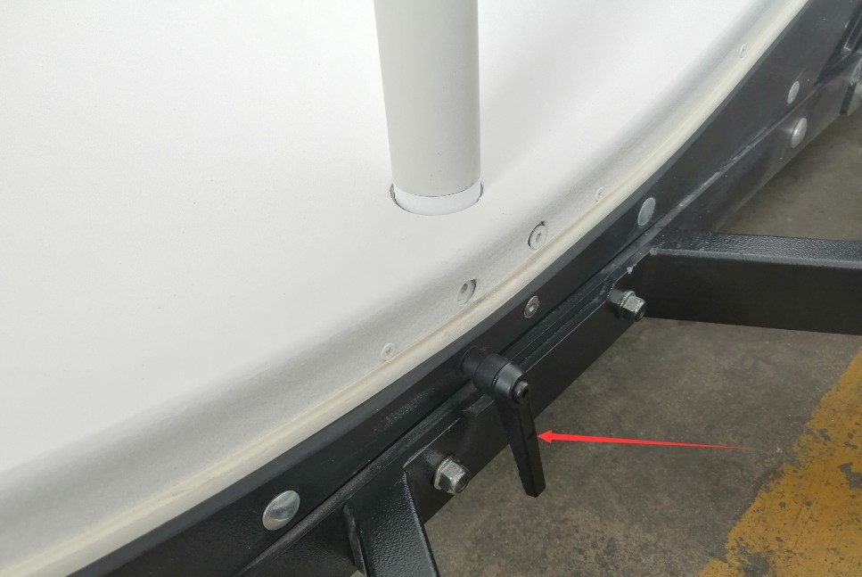
Figure 4
3.1.2 Four-Conductor Cable Connection for the Stage
The stage’s four-wire cable must be connected to the back of the junction box at the bottom of the Integrating Sphere. The junction box contains red and black terminals for POWER and SENSE, for a total of four terminals. The stage also contains red and black terminals for POWER and SENSE, for a total of four terminals. When making the connections, open the stage top cover and the junction box to verify that the wiring is correct and that each terminal corresponds to its respective connection.
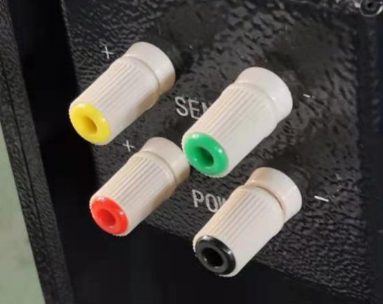
Figure 5
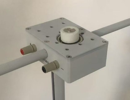
Figure 6
3.2 Installation of Linear Light Fixtures (No linear light fixtures for diameters less than 1.5 m)
When you need to test linear lights, such as LED tubes, you can use a linear light fixture to secure the tube.
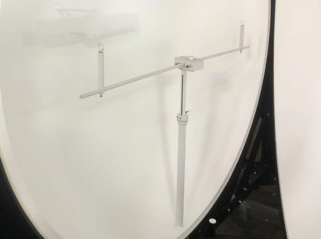
Figure 7
3.3 Installation of Auxiliary Light Fixtures (Models with a diameter of less than 1 m do not have an auxiliary light function)
Remove the plugs from the mounting holes on the Integrating Sphere auxiliary light bracket to prepare for installing the auxiliary light bracket.
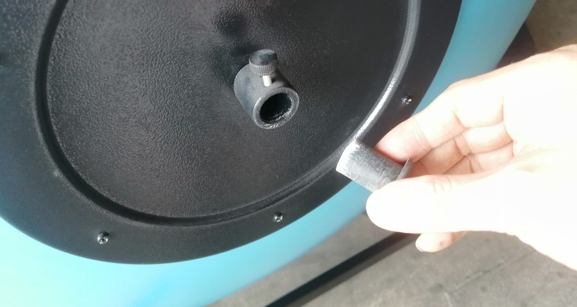
Figure 8
Find the auxiliary light fixture:
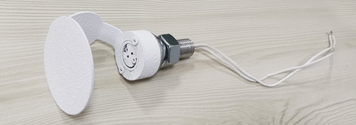
Figure 9
Remove the screws and washers:
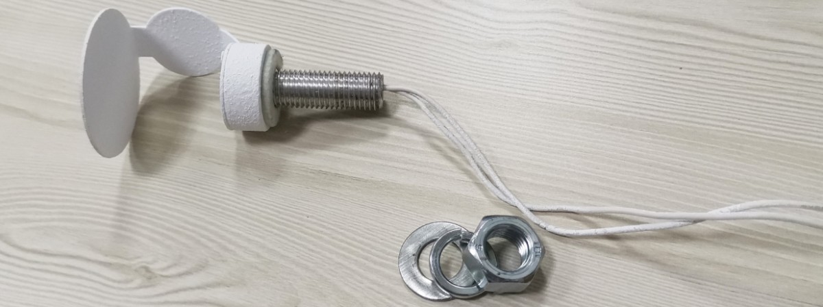
Figure 10
Feed the auxiliary light fixture out from the inside of the Integrating Sphere:
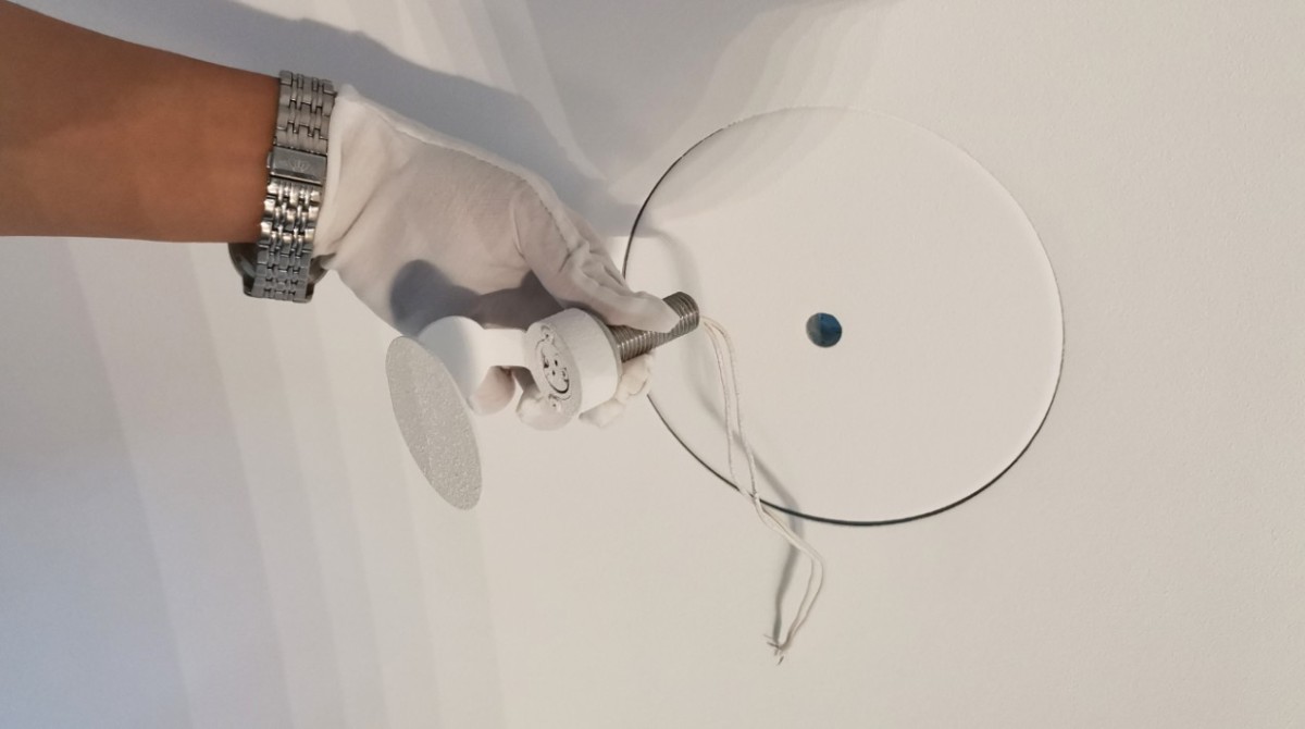
Figure 11
Then secure it from the outside using screws and washers.
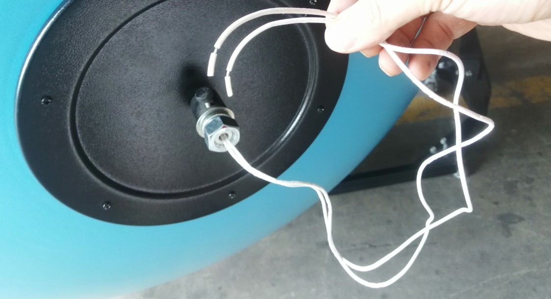
Figure 12
3.4 Crosshair Laser (No crosshair laser for diameters less than 1.5 m)
3.4.1 Cross-Laser Calibration
| Number | Note |
| ① | Battery compartment, used to power the crosshair laser |
| ② | Cross-Line Laser Switch |
| ③ | Cross-hair laser and its mounting screws |
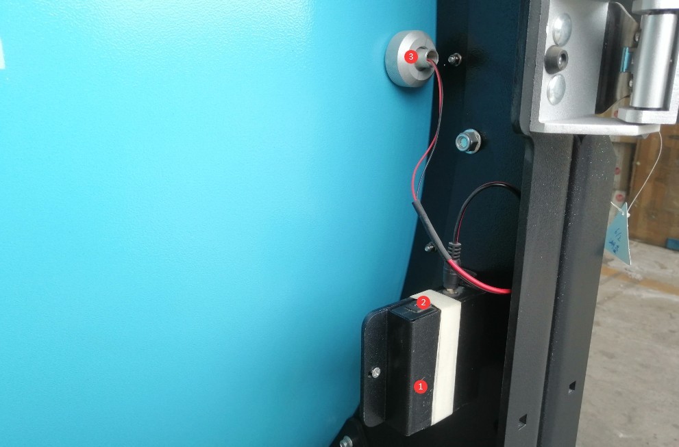
Figure 13
Turn on the crosshair laser. The alignment of the crosshair laser may have shifted during shipping. Use a tape measure to confirm the center position of the Integrating Sphere, loosen the screw securing the crosshair laser, readjust the crosshair laser so that it is directly over the center of the Integrating Sphere, and then tighten the screw securely.
3.4.2 Uses of Cross-Line Lasers
The crosshair laser is used to assist with light installation. Turn on the crosshair laser during installation to ensure that the light-emitting surface of the installed light is positioned exactly at the center of the Integrating Sphere. Turn off the crosshair laser during testing.
4. Operating and Using The Integrating Sphere
4.1 Connecting Spectrometer Accessories
Spectrometer accessories, including Optical Fibers, photometric probes, and temperature probes, with connectors suitable for connection to an Integrating Sphere.
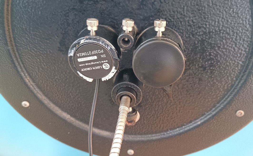
Figure 14
4.2 Installation and Connection of Sample Luminaires
4.2.1 Small Integrating Sphers (diameter less than 1 m)
The 0.3-meter Integrating Sphere can only accommodate MR16 samples, while the 0.5-meter Integrating Sphere can accommodate samples with E27 bases (or samples connected to an E27 adapter). Simply install the sample directly; no additional wiring is required inside the Integrating Sphere.
Note: The fixture position is adjustable; ensure that the sample’s light-emitting surface is centered within the Integrating Sphere.
4.2.2 Medium- to Large-Sized Integrating Sphers (Diameter of at Least 1 m)
4.2.2.1 Bulb Lights and Strip Lights
For incandescent bulbs, the mount includes an E27 socket. Incandescent bulbs can be installed directly into the E27 socket or connected to it using an adapter; no additional wiring is required inside the Integrating Sphere.
For strip lights, refer to Section 3.2 and use strip light fixtures.
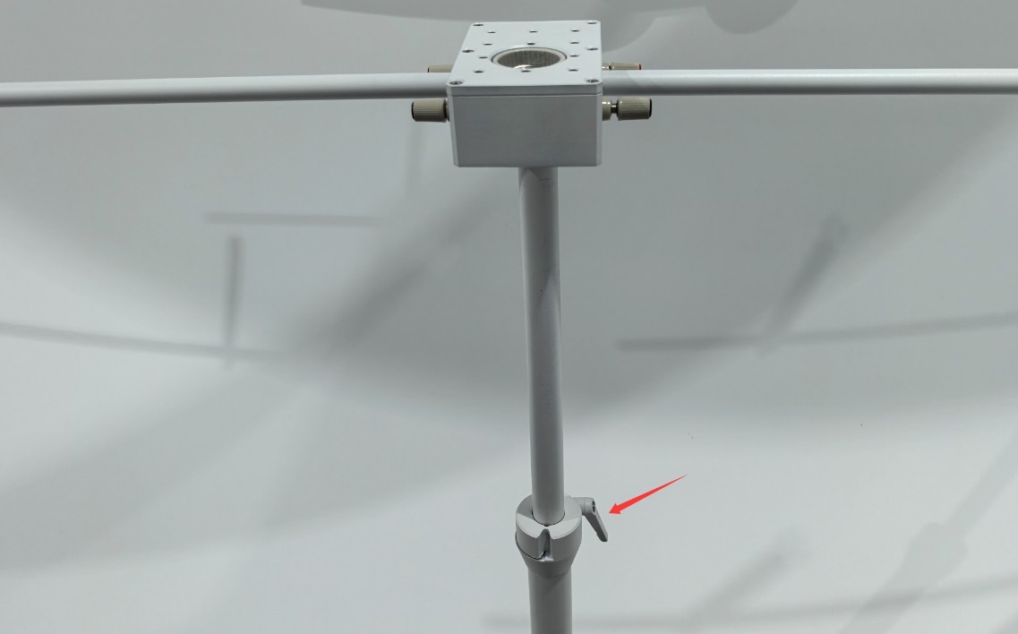
Figure 15
4.2.2.2 Other Lighting Fixtures
For other types of lighting fixtures, they can be placed directly on the stage. The stage surface has screw holes, so you can use M6 screws to secure the fixture to the stage to prevent it from falling.
4.2.2.3 Confirmation of the Light-Emitting Surface Installation Location
The stage is height-adjustable. The 1-meter Integrating Sphere does not have a crosshair laser; use a tape measure to ensure the sample’s light-emitting surface is positioned exactly at the center of the Integrating Sphere. For Integrating Sphères of 1.5 meters or larger, refer to Section 3.4.2 and use the crosshair laser to ensure the sample’s light-emitting surface is positioned exactly at the center of the Integrating Sphere. After adjusting the height, ensure that the screws are securely tightened to prevent the stage from falling suddenly.
4.2.2.4 Connecting the Sample Power Cord
Simply connect the sample power cord to the two terminals labeled “POWER” on the stage. The two red terminals and two black terminals labeled “POWER” and “SENSE” on the stage are internally shorted; therefore, there is no need to connect wires separately to the two terminals labeled “SENSE” on the stage.
4.3 Connecting the External Power Cable and Sampling Cable
The four terminals on the front of the Integrating Sphere junction box are used to connect to your other devices. The two “POWER” terminals connect to the sample power supply cable, and the two “SENSE” terminals connect to the voltage sampling cable.
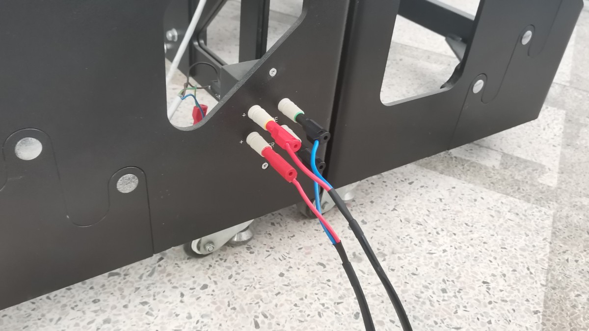
Figure 16
4.4 Use of Auxiliary Light Mounts (No auxiliary light function for diameters less than 1 m)
Please install the auxiliary light into the MR16 socket on the auxiliary light fixture. The auxiliary light fixture has two pre-wired power lines; when you need to use the auxiliary light, please use a wire to extend the connection and connect the auxiliary light to a suitable power source.
Figure 17
5. Procedures for Shutting Down The Integrating Sphere
5.1 Remove the sample promptly
Promptly remove the sample and wiring from inside the Integrating Sphere; do not leave any unrelated accessories inside the Integrating Sphere.
5.2 Close The Integrating Sphere promptly
When the Integrating Sphere is not in use, be sure to keep it closed to prevent dust from entering.
6. Routine Maintenance and Care of Equipment
6.1 Routine Internal Dust Cleaning
Frequency: At least once a week; Tools: Cold-air hair dryer (do not use hot air); Method: Gently blow away dust from inside the ball; do not allow any objects to come into contact with the coating.
6.2 Items for Regular Inspection
6.2.1 Structural and Opening/Closing Inspection
Each month, check the opening and closing handles and hinges; if any are loose, tighten the screws. Check that the gap between the two halves is even and that no light leaks through.
6.2.2 Inspection of the Inner Wall Coating
Inspect the interior coating monthly to ensure there is no peeling, yellowing, darkening, or staining.
6.3 Guidelines for Long-Term Storage
Storage Conditions: Dry, protected from light, dust-free, temperature 0–40°C, relative humidity ≤70% RH; ensure the sphere is fully closed and covered with a dust cover; perform a thorough cleaning and inspection before storage.
7. Common Problems and Solutions
| Frequently Asked Questions | Procedure |
| How should an Integrating Sphere be disassembled for easy transport? | Large Integrating Sphères are quite bulky. If you must disassemble one for transport, unscrew all the black hand-tightening screws at the joint between the two halves (do not remove any other screws) to separate the Integrating Sphere into two parts. Be sure to protect the coating on the inner walls of the Integrating Sphere during transport, as damage to the coating is very difficult to repair. |
| How to Install LISUN’s 10W Standard Light and Auxiliary Light | Wearing gloves, carefully remove the light bulb from its E27 socket, then install it into the corresponding MR16 socket. |
| Small areas of the coating on the inner wall of the Integrating Sphere have peeled off | If a sample luminaire is accidentally dropped, causing a small area of the coating on the inner wall of the Integrating Sphere to peel off, please contact us to obtain the necessary paint for repair. |
| Extensive peeling of the inner wall coating of the Integrating Sphere | If the inner coating has peeled off over a large area due to frequent bumps or drops of the fixture, and the coating cannot be repaired, please purchase a new Integrating Sphere. |
| The coating on the inner wall of the Integrating Sphere has darkened and yellowed over a large area. | If the device is left uncovered for an extended period, dust is not cleaned off promptly, or it is used in harsh environments—such as those with excessive temperature or humidity, or direct sunlight—resulting in extensive yellowing of the inner wall coating that cannot be repaired, please purchase a new Integrating Sphere. |
8. Packing List
| No. | Name | Quantity |
| ① | Integrating Sphere | 1 |
| ② | MR16 lamp holder (built into the IS-0.3M only) | |
| ③ | E27 lamp holder (IS-0.3M not included) | |
| ④ | E27-MR16 Adapter (IS-0.3M not included) | |
| ⑤ | Cross-line laser (built into Integrating Sphères with a diameter of at least 1.5 m only) | |
| ⑥ | Stage (excluding Integrating Sphères with a diameter of less than 1 m) | |
| ⑦ | Linear light fixtures (excluding Integrating Sphères with a diameter of less than 1.5 m) | 1 set |
| ⑧ | Auxiliary lighting fixtures (excluding Integrating Sphères with a diameter of less than 1 m) | 1 |