
 English
 中文简体
中文简体 English
 Русский
 Español
 Português
 Türkçe
 العربية
 Deutsch
 Polski
 Italiano
 Français
 한국어
한국어 ไทย
ไทย Tiếng Việt
 日本語
日本語





























Plug Torque Tester
User's Manual
Applicable LISUN models: LSPTT-1
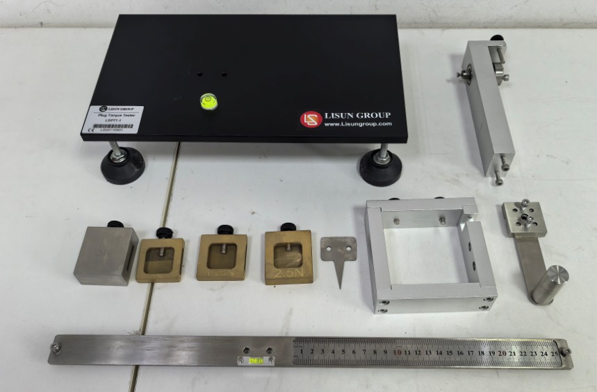
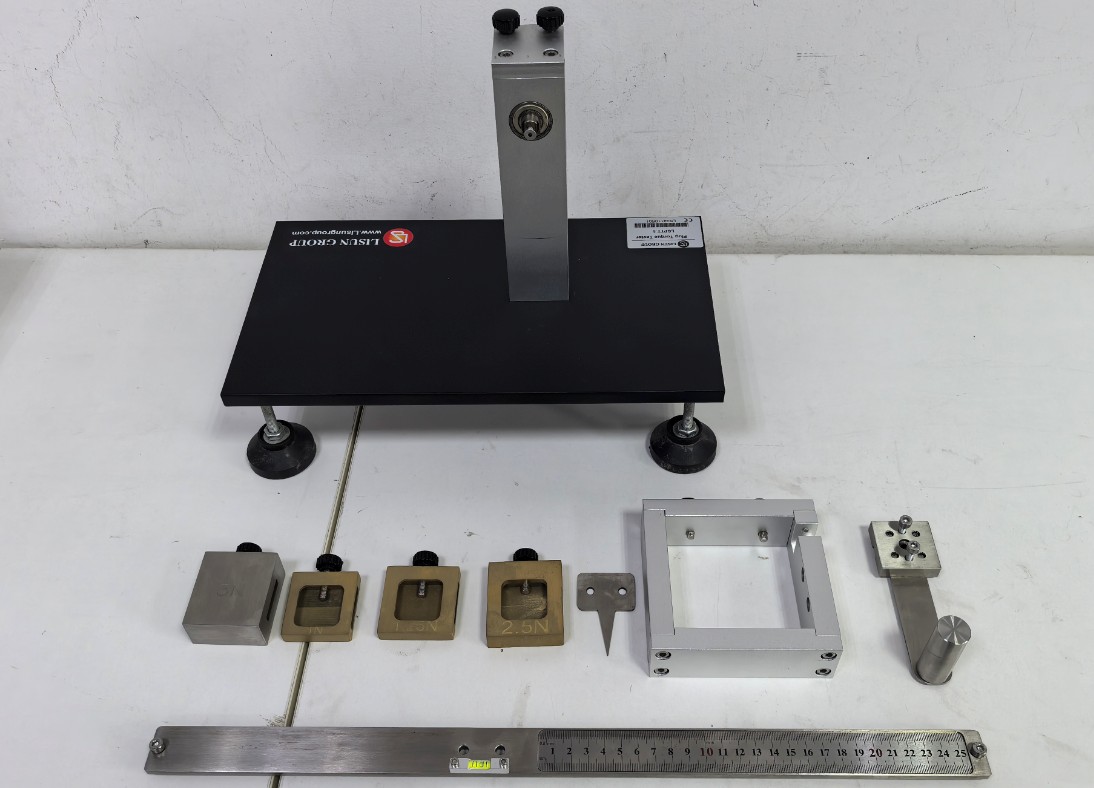
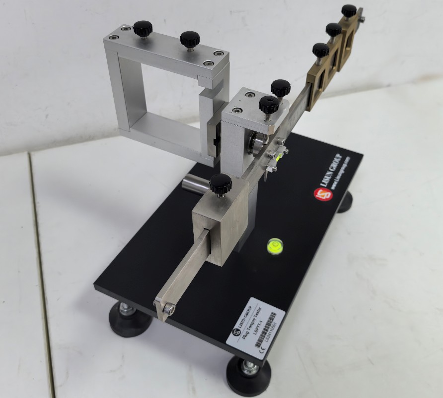
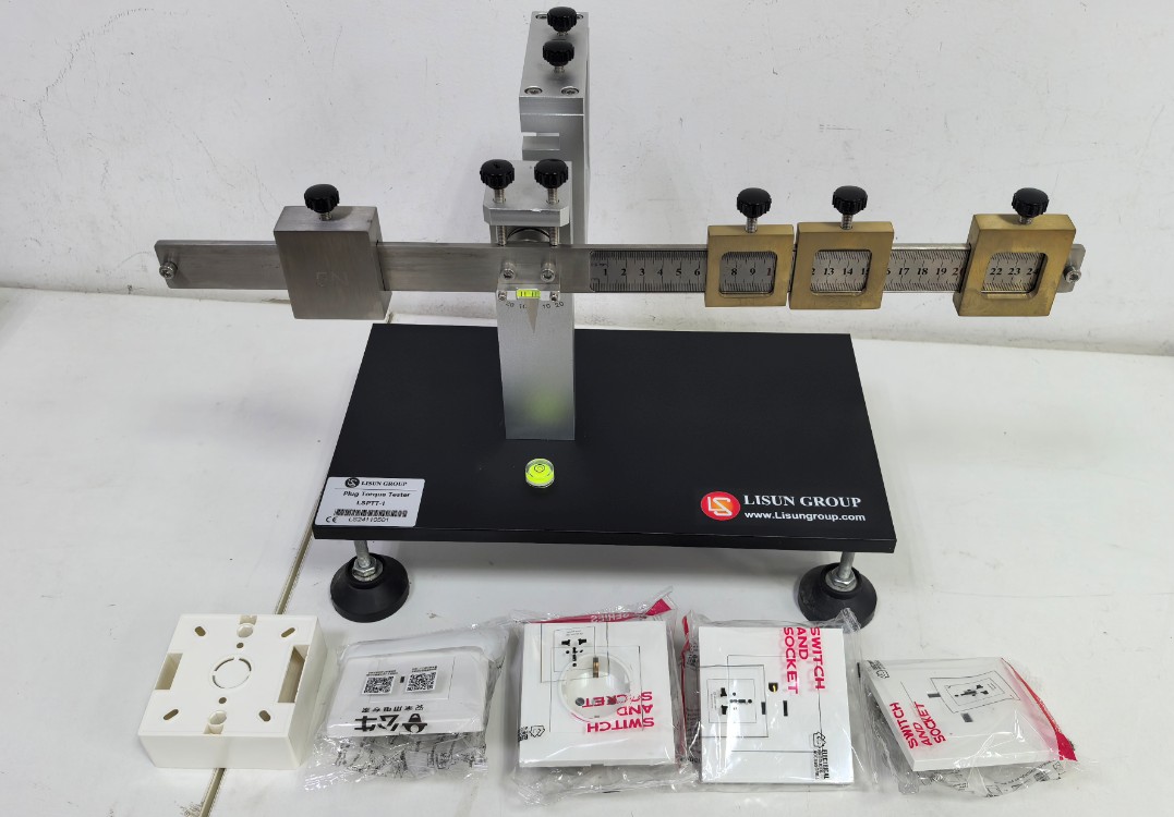
To prevent damage during shipping, your equipment may have been shipped in separate packages. Please open all packages. All parts are listed below:
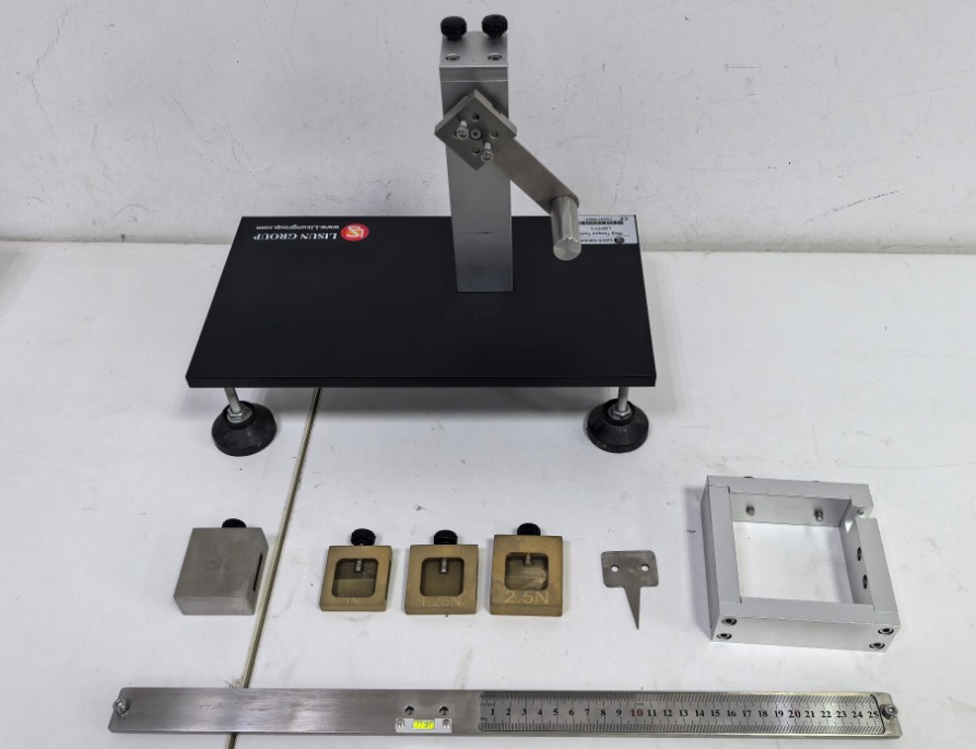
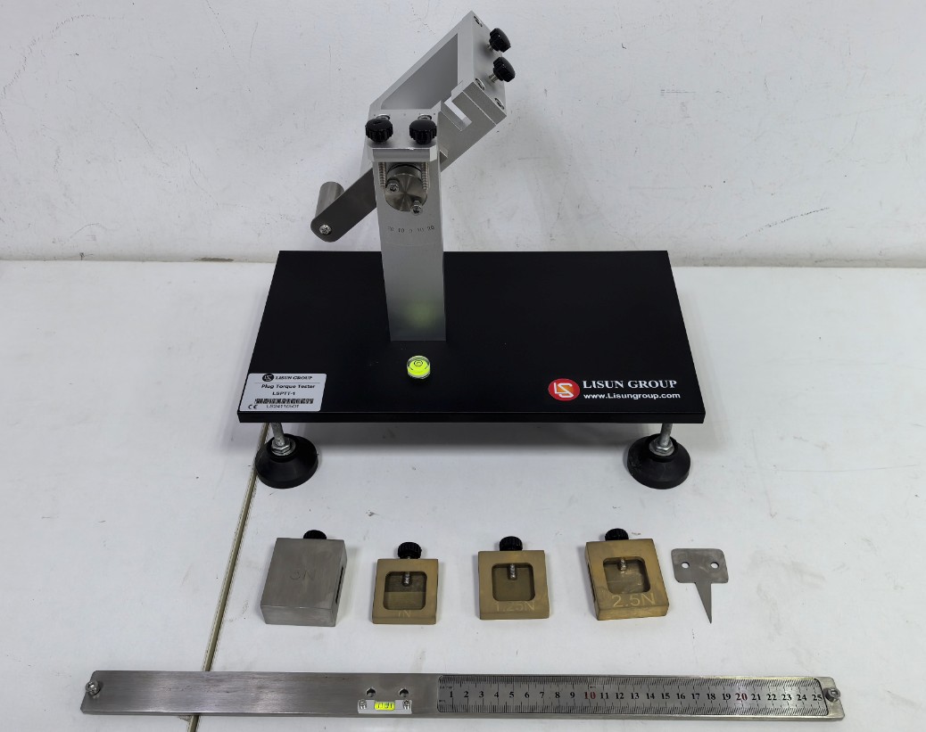
Follow the steps in the diagram below to assemble the equipment:
The equipment comes with several common types of outlets to facilitate testing. See the figure below:
Important Notes
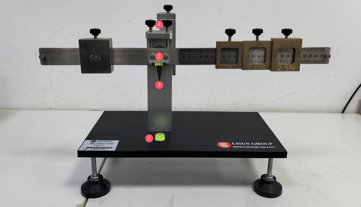
Place the device on a stable, level surface. Adjust the base, referring to the bubble at point = 1 * GB3①, to ensure the entire device is level. Adjust the gap between the screws at = 2 * GB3②, using the bubble on the steel ruler as a reference, to ensure that when the pointer at = 3 * GB3③ points to the 0-degree position, the steel ruler is level. Note: When adjusting the steel ruler, you will need to loosen or tighten the two thumb screws at = 4 * GB3④ as needed.
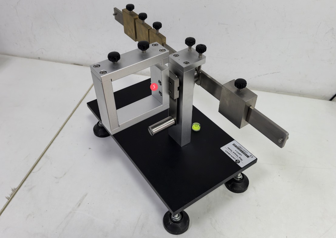
Adjust the screw clearance at = 5 * GB3⑤ so that the socket clamp is in a vertical position.
Equipment Use
Adjust the test weight on the right side of the device so that its left edge is positioned 10 mm from the steel ruler, then adjust the balancing weight on the left side to level the balance arm, then check whether the spirit level on the balance arm is level (the bubble in the center indicates a level position). If it is level, the mating surface of the output socket is in a vertical position; if it is not level, fine-tune the balance arm further.
Insert the sample into the output socket, and adjust the position of the weight on the balance beam to the right so that the mating surface is vertical (check to see if the spirit level bubble is centered).
Read the value on the steel ruler, multiply it by the weight of the weight, and the result is the torque applied by the sample to the output socket. Alternatively, place a 2.5-N weight at a distance of 100 mm from the starting point of the balance arm(The left edge of the test weight on the right side of the apparatus is located 10 mm from the steel ruler) at the 100 mm mark, and determine whether the torque applied by the specimen is within the range specified by the standard by observing the position of the balance arm.
Photometric, Colorimetric, and Safety Performance Testing Solutions for LEDs
Goniophotometer System: LSG-6000, LSG-1890B, or LSG-1800ACCD
Spectroradiometer & Integrating Sphere Test System: LPCE-2 or LPCE-3
LED Life Maintains a Test System in Accordance with LM-84: LEDLM-84PL
Photobiological Radiation Safety Test System: EN 62471-C or EN 62471-P
Lamp Start, Run-up Time, and Flicker Test System: LSRF-3 and LSP-500VARC-Pst
LED Power Driver Testers: LS2090, M9822, and LSP-500VARC
IK Level Tester | Spring Hammer Impact Tester: IK07-10, IK01-06
Electrodynamic Vibration Generator System: LVD-100KG-6D
Electrical Safety Testers: LS9955, ZRS-3H, ZY-3, TTC-1
Environmental Chamber Test Solution for LED Luminaires
Waterproof Test for IPX5 and IPX6: JL-56
Dustproof Testing Machine for IP5X and IP6X: SC-015
High- and Low-Temperature and Humidity Chamber: GDJS-015B
Salt Spray Test Machine: YWX/Q-010
UV Lamp Aging Test Chamber: UV-263LS
Xenon Lamp Aging Test Chamber: XD-80LS
Ozone Test Chamber: OTC-150A
Sulfur Dioxide Test Chamber: SQ-010
EMC and EMI Test Solutions for CFL and LED Luminaires
EMI Test System: EMI-9KB or EMI-9KA
Electrostatic Discharge Simulator: ESD61000-2
EFT Immunity Measurement: EFT61000-4
Surge Generator: SG61000-5
Voltage Dips and Interruptions Generator: CSS61000-11
Ring Wave Generator: RWG61000-12

www. Lisungroup.com
Patents Filed
All Rights Reserved by Lisun Group
Subject to Change Without Notice