
 English
 中文简体
中文简体 English
 Русский
 Español
 Português
 Türkçe
 العربية
 Deutsch
 Polski
 Italiano
 Français
 한국어
한국어 ไทย
ไทย Tiếng Việt
 日本語
日本語





























LCR Meter With DC Bias Current Source
User's Manual
Applicable LISUN models: LS1373CX、LS1373X、LS1379CMX、LS1379MX
The LS1373 is an LCR Meter with a built-in high-frequency LCR digital bridge and a DC bias current source ranging from -12 to 12 A. With a current resolution as low as 0.125 mA, it can analyze the characteristics of inductor cores for inductor quality inspection or product characteristic analysis. The built-in bias current source features lower noise and more flexible control, and includes an integrated comparator, making it easy to integrate into automated production lines for inductor testing.
1. Product Overview
This chapter introduces the product positioning and key performance characteristics of the LS1373 LCR Meter with DC Bias Current Source.
1.1 Performance Features
Provides a maximum constant current output of 12A per unit
0.125 mA fine-tuned current increments
Forward/Reverse Switching Function for Superimposed Current
Supports automatic current continuation after the circuit is opened
Supports the ability to set the duration of the current boost
Two current output modes: constant current and step scanning
Graphical user interface, available in both Chinese and English
Built-in comparator, making it easy to integrate into automated production lines for inductor testing
2. Technical Specifications
2.1 Technical Specifications of the Superimposed Current Source
| Technical Specifications | Technical Specifications | Technical Specifications | Technical Specifications | Technical Specifications |
| Model | Model | LS1373 | LS1373 | LS1373 |
| Show | Show | 7″ LCD | 7″ LCD | 7″ LCD |
| Operations | Operations | Physical buttons + foot switch | Physical buttons + foot switch | Physical buttons + foot switch |
| Supported Measurement Frequencies | Supported Measurement Frequencies | 50 Hz–500 kHz; C-type: custom-made up to 1 MHz | 50 Hz–500 kHz; C-type: custom-made up to 1 MHz | 50 Hz–500 kHz; C-type: custom-made up to 1 MHz |
| Current Range | Current Range | -12A to 12A | -12A to 12A | -12A to 12A |
| Current Accuracy | Current Accuracy | ±1% ±5 mA | ±1% ±5 mA | ±1% ±5 mA |
| Current | Measurement Range | 0 mA–0.500 A | 0.500 A to 2.500 A | 2.5 A–12 A |
| Current | Step-by-step | 0.125 mA | 0.625 mA | 3.125 mA |
| Maximum Output Voltage | Maximum Output Voltage | 11V (Outputs 11V under all current conditions) | 11V (outputs 11V under all current conditions) | 11V (Outputs 11V under all current conditions) |
| Maximum Allowable DC Resistance | Maximum Allowable DC Resistance | Rmax = Vmax/I (Ω) | Rmax = Vmax/I (Ω) | Rmax = Vmax / I (Ω) |
| Maximum Allowable Inductance | Maximum Allowable Inductance | Lmax = Vmax / (di/dt) (mH) | Lmax = Vmax / (di/dt) (mH) | Lmax = Vmax / (di/dt) (mH) |
| Range Selection Method | Range Selection Method | Automatic | Automatic | Automatic |
| Start and Stop Control Methods | Start and Stop Control Methods | START/STOP physical buttons, 4 types of foot controls, bus | START/STOP physical buttons, 4 types of foot controls, bus | START/STOP physical buttons, 4 types of foot controls, bus |
| Maximum Continuous Current Load Duration | Maximum Continuous Current Load Duration | Runs for 2 to 3 hours with continuous output | Runs for 2 to 3 hours with continuous output | Runs for 2 to 3 hours with continuous output |
| Interface | Interface | RS232C, USB Host, USB Device, Handler | RS232C, USB Host, USB Device, Handler | RS232C, USB Host, USB Device, Handler |
2.2 Technical Specifications of the LCR Meter
| Technical Specifications | Technical Specifications | Technical Specifications | Technical Specifications | Technical Specifications | Technical Specifications |
| Model | Model | LS1373 | LS1373A | LS1373B | LS1373C |
| Test Frequency | Test Frequency | 50 Hz to 200 kHz | 50 Hz–300 kHz | 50 Hz–500 kHz | 50 Hz to 1 MHz |
| Test Frequency | Test Frequency | More than 12000 frequency points | More than 12000 frequency points | More than 12000 frequency points | More than 12000 frequency points |
| Test Parameters | Test Parameters | C, L, X, B, R, G, D, Q, ESR, Rp, θ, |Z|, |Y| | C, L, X, B, R, G, D, Q, ESR, Rp, θ, |Z|, |Y| | C, L, X, B, R, G, D, Q, ESR, Rp, θ, |Z|, |Y| | C, L, X, B, R, G, D, Q, ESR, Rp, θ, |Z|, |Y| |
| Test Level | Test Level | 50 mV to 2 V rms | 50 mV to 2 V rms | 50 mV to 2 V rms | 50 mV to 2 V rms |
| Accuracy | Accuracy | 0.1% (LCR connection method only; basic accuracy at 1 kHz, at the midpoint of the measurement range) | 0.1% (LCR connection method only; basic accuracy at 1 kHz reference range) | 0.1% (LCR connection method only; basic accuracy at 1 kHz reference range) | 0.1% (LCR connection method only; basic accuracy at 1 kHz, near full scale) |
| Test Speed | Test Speed | Fast: 50 times/second, Medium: 20 times/second, Slow: 6 times/second (at frequencies above 1 kHz without current applied) | Fast: 50 times/second, Medium: 20 times/second, Slow: 6 times/second (at frequencies above 1 kHz without current) | Fast: 50 times/second, Medium: 20 times/second, Slow: 6 times/second (at frequencies above 1 kHz without current applied) | Fast: 50 times/second, Medium: 20 times/second, Slow: 6 times/second (at frequencies above 1 kHz without current applied) |
| Display Range | |Z|, R, X | 0.01 mΩ to 99.9999 MΩ | 0.01 mΩ to 99.9999 MΩ | 0.01 mΩ to 99.9999 MΩ | 0.01 mΩ to 99.9999 MΩ |
| Display Range | |Y|, G, B | 0.00001 μS to 99.9999 S | 0.00001 μS to 99.9999 S | 0.00001 μS to 99.9999 S | 0.00001 μS to 99.9999 S |
| Display Range | C | 0.00001 pF to 9.99999 F | 0.00001 pF to 9.99999 F | 0.00001 pF to 9.99999 F | 0.00001 pF to 9.99999 F |
| Display Range | D | 0.00001–9.99999 | 0.00001–9.99999 | 0.00001–9.99999 | 0.00001–9.99999 |
| Display Range | L | 0.00001 μH to 99999.9 H | 0.00001 μH to 99999.9 H | 0.00001 μH to 99999.9 H | 0.00001 μH to 99999.9 H |
| Display Range | Q | 0.01–99999.9 | 0.01–99999.9 | 0.01–99999.9 | 0.01–99999.9 |
| Display Range | θ (RAD) | -3.14159 to 3.14159 | -3.14159 to 3.14159 | -3.14159 to 3.14159 | -3.14159 to 3.14159 |
| Display Range | θ(DEG) | -179.999° to 179.999° | -179.999° to 179.999° | -179.999° to 179.999° | -179.999° to 179.999° |
| Display Range | Δ% | -99.999% to 99.999% | -99.999% to 99.999% | -99.999% to 99.999% | -99.999% to 99.999% |
| Signal Source Output Impedance | Signal Source Output Impedance | 30Ω, 100Ω, 1062X | 30Ω, 100Ω, 1062X | 30Ω, 100Ω, 1062X | 30Ω, 100Ω, 1062X |
| Range Selection Method | Range Selection Method | Auto, Hold | Auto, Hold | Auto, Hold | Auto, Hold |
| Trigger Method | Trigger Method | Internal, Manual, Automatic, External | Internal, Manual, Automatic, External | Internal, Manual, Automatic, External | Internal, Manual, Automatic, External |
| Calibration Function | Calibration Function | Open Circuit, Short Circuit, Full-Frequency Reset, Spot-Frequency Reset | Open Circuit, Short Circuit, Full-Frequency Reset, Spot-Frequency Reset | Open Circuit, Short Circuit, Full-Frequency Reset, Spot-Frequency Reset | Open Circuit, Short Circuit, Full-Frequency Reset, Spot-Frequency Reset |
| Equivalent Circuit | Equivalent Circuit | Series, Parallel | Series, Parallel | Series, Parallel | Series, Parallel |
| Comparator | Comparator | Three-tier sorting: BIN 0–BIN 2 | Three-tier sorting: BIN 0–BIN 2 | Three-tier sorting: BIN 0–BIN 2 | Three-tier sorting: BIN 0–BIN 2 |
| Comparator | Comparator | PASS, HI, LOW (PASS/FAIL LED indicator) | PASS, HI, LOW (PASS/FAIL LED display) | PASS, HI, LOW (PASS/FAIL LED indicator) | PASS, HI, LOW (PASS/FAIL LED display) |
3. Terms of Use
3.1 Power Supply

Factory default power supply voltage: 100–242 VAC;
Power Supply Frequency: 46–64 Hz
Power consumption: ≤300 VA
3.2 Ambient Temperature and Humidity
Normal operating temperature: 0°C to 40°C; humidity: < 90% RH
Reference operating temperature: 20°C ± 8°C; humidity: < 80% RH
Transportation ambient temperature: 0°C to 55°C; humidity: 93% RH
3.3 Preheating
After turning it on, let it warm up briefly before use.
3.4 Points to Note

(1) Please do not use this product in adverse environments such as those with dust, vibration, direct sunlight, or corrosive gases.
(2) If the instrument will not be used for an extended period, please place it in its original packaging or a similar box and store it in a well-ventilated room at a temperature between 5°C and 40°C and a relative humidity of no more than 85% RH. The air should be free of harmful impurities that could corrode the instrument, and direct sunlight should be avoided.
(3) This instrument has been carefully designed to minimize noise interference from the AC input power supply; however, it should still be used in a low-noise environment whenever possible. If this is unavoidable, please install a power filter.
3.5 Volume and Weight
Width × Height × Depth: 395 mm × 135 mm × 465 mm
Weight: 9.9 kg
3.6 Safety Requirements
This instrument is a Class I safety instrument.
(1) Insulation Resistance
Under reference operating conditions, the insulation resistance between the power supply terminals and the enclosure shall be no less than 50 MΩ;
Under humid and hot transport conditions, the insulation resistance between the power terminals and the enclosure shall be no less than 2 MΩ;
(2) Dielectric Strength
Under reference operating conditions, the power supply terminals and the enclosure can withstand an AC voltage of 1.5 kV at a frequency of 50 Hz for 1 minute without breakdown or arcing.
(3) Leakage current
The leakage current must not exceed 3.5 mA.
3.7 Electromagnetic Compatibility
(1) Power supply transient immunity shall comply with the requirements of GB 6833.4.
(2) Conduction sensitivity shall comply with the requirements of GB 6833.6.
(3) Radiated interference shall comply with the requirements of GB 6833.10.
4. Panel Description
4.1 Front Panel Description
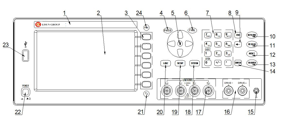
Figure 2-1 Front Panel
1. Trademarks and Model Numbers
Instrument brand, model number, measurement range, etc.
2. LCD Display
Extra-large 800×480 dot-matrix LCD display that shows settings, measurement results, measurement conditions, and more.
3. Soft Keys
Six soft keys are available for selecting controls and parameters; the function of each soft key is defined to the left of it. The soft key definitions vary depending on the display page.
4. PASS LED
The test results are indicated by an LED light.
5. NEXT button
The fast page-turn keys are only useful during the Voltage Transformer scan test function.
6. FAIL LED
The test failed due to the LED light.
7. Number Keys
Used to enter numbers and other relevant information.
8. The ESC key
Finish entering the numbers on the numeric keypad.
9. [←] key
The BACKSPACE key. Press this key to delete the last character of the entered value.
10. KEYLOCK Key
Press the [KEYLOCK] button; the [KEYLOCK] indicator will light up, indicating that the panel buttons are currently locked. Press the [KEYLOCK] button again, and the [KEYLOCK] button will turn off, indicating that the keypad lock has been released. If the password function is set to “ON,” you must enter the correct password to release the keypad lock; otherwise, the keypad lock cannot be released.
When the instrument is controlled via a bus (such as USBTMC), the [KEYLOCK] button will light up. Press the [KEYLOCK] button again, and it will turn off, indicating that the instrument has returned to local mode and the keyboard lock has been released.
11. [DC BIAS] Button
Used to enable or disable the DC bias output. Press the [DC BIAS] key; the [DC BIAS] indicator will light up, indicating that the DC bias output is enabled; Press the [DC BIAS] key again, and the [DC BIAS] key will turn off, indicating that DC bias output is disabled. On certain non-test screens where DC bias cannot be applied, pressing this key will have no effect.
12. [RESET] button
Press the [RESET] button to stop the scan while the Voltage Transformer is being automatically scanned; the instrument will not perform any operations on other pages.
13. [TRIGGER] key
When the instrument’s trigger mode is set to MAN (Manual) mode, press this key to trigger the instrument to perform a test.
14. [ENTER] key
When entering values, press the [ENTER] key to complete data entry, confirm, and save the data displayed on the bottom line of the LCD.
When entering a filename, press the [ENTER] key to complete the entry, confirm, and save the filename displayed on the bottom line of the LCD.
15. Chassis Ground Terminal
This terminal is connected to the instrument housing. It can be used for protective or shielding ground connections.
16. DC bias current output terminal
Used to connect to the inductor under test and apply a DC bias current to it
DC Bias Current, Positive Terminal (DRIVE+)
DC Bias Current (Negative Terminal) DRIVE-
17. Test End (UNKNOWN)
Four-terminal to test terminal. Used to connect a four-terminal test fixture or test cable for measuring the device under test.
High-side current drive (Hcur);
High-side voltage sampling (Hpot);
Low-end voltage sampling (Lpot);
Low-end current drive (Lcur).
18. [SYSTEM] Menu Key
Press the [SYSTEM] button to access the “System Settings” page.
19. [SETUP] Menu Button
Press the [SETUP] button to enter the “Measurement Settings” main screen.
20. [LCRZ] Menu Key
Press the [LCRZ] key to enter the “Component Measurement Display” page.
21. [RETURN] Menu Key
Back button: On certain settings pages, press this button to return to the previous menu.
22. Power Switch (POWER)
Press this button to turn the power on or off.
23. USB HOST Port
Used to connect a USB flash drive.
4.2 Rear Panel Description
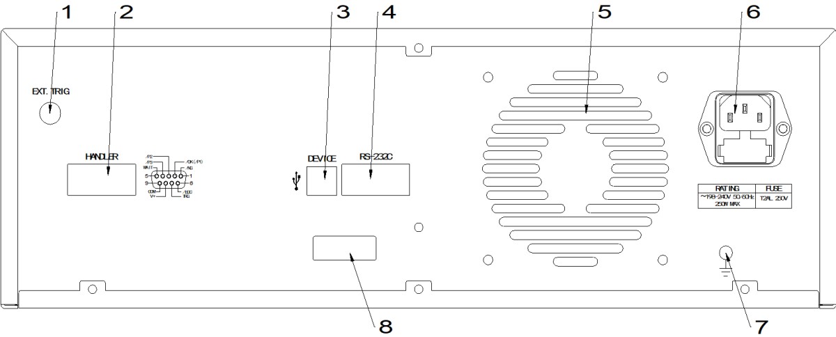
Figure 2-2: Rear Panel
1. EXT. TRG
Foot switch connector.
2. HANDLER Port
The HANDLER interface makes it easy to set up automated test systems and perform automated testing, and is widely used in automated factory production lines. The instrument uses this interface to output range comparison results and status signals, and also receives the “Start” signal through this interface.
3. USBDEVICE Interface
The USBDEVICE interface enables a computer to control the LCR digital bridge.
When the bus mode is set to USBTMC, this port functions as a USBTMC interface.
When the bus mode is set to USBCDC, this port functions as a USBCDC interface (virtual serial port).
When the bus mode is set to USBHID, this port functions as a USBHID interface (virtual keyboard interface).
4. RS232C Serial Interface
Serial communication interface, which allows the computer to control the instrument.
5. Ventilation Window
Heat dissipation to maintain the instrument at its normal operating temperature.
6. Electrical Outlet
Used to connect to an AC power source.
7. Ground Terminal
This terminal is connected to the instrument housing. It can be used for protective or shielding ground connections.
8. Barcode Labeling Area
Used for affixing instrument barcodes.
4.3 Screen Areas: Names and Functions of Each Section
The LS1373 features a 7-inch LCD display with a resolution of 800×480, and the functional layout of its display area is shown in Figure 2-3.
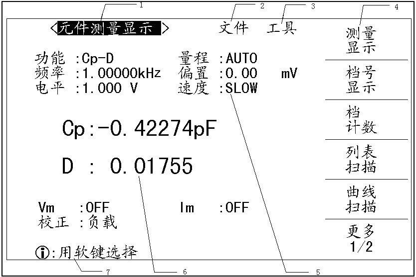
Figure 2-3 shows the functional zoning of the area
Display Page Area
This area displays the name of the current page.
Document Field
Move the cursor to this area to perform file management operations. File management operations include: loading, saving, and deleting.
Tools Section
Some less commonly used features, for which there are no corresponding settings fields on the display page, are listed in the “Tools” section.
Soft Key Area
This area is used to display the function definitions for soft keys. The function definitions for soft keys vary depending on the position of the cursor within the field.
Function Display Area
This area displays the test conditions and functions that have been set.
Measurement Results Area
This area displays test result information
Message Prompts and Data Entry Areas
This area is used to display system prompts and user data entries.
Instructions for Use
To help users get started quickly, this user manual provides operating instructions only for the LS1373’s superimposed current test function. For operating instructions regarding the LCR bridge functions, users should refer to our company’s *LCR Digital Bridge General User Manual*.
5. Operating Instructions
5.1 Installation, Connection, and Testing
5.1.1 Connecting the Test Cable
5.1.1.1 Connect the inductor under test using the LS1373Y03 test cable
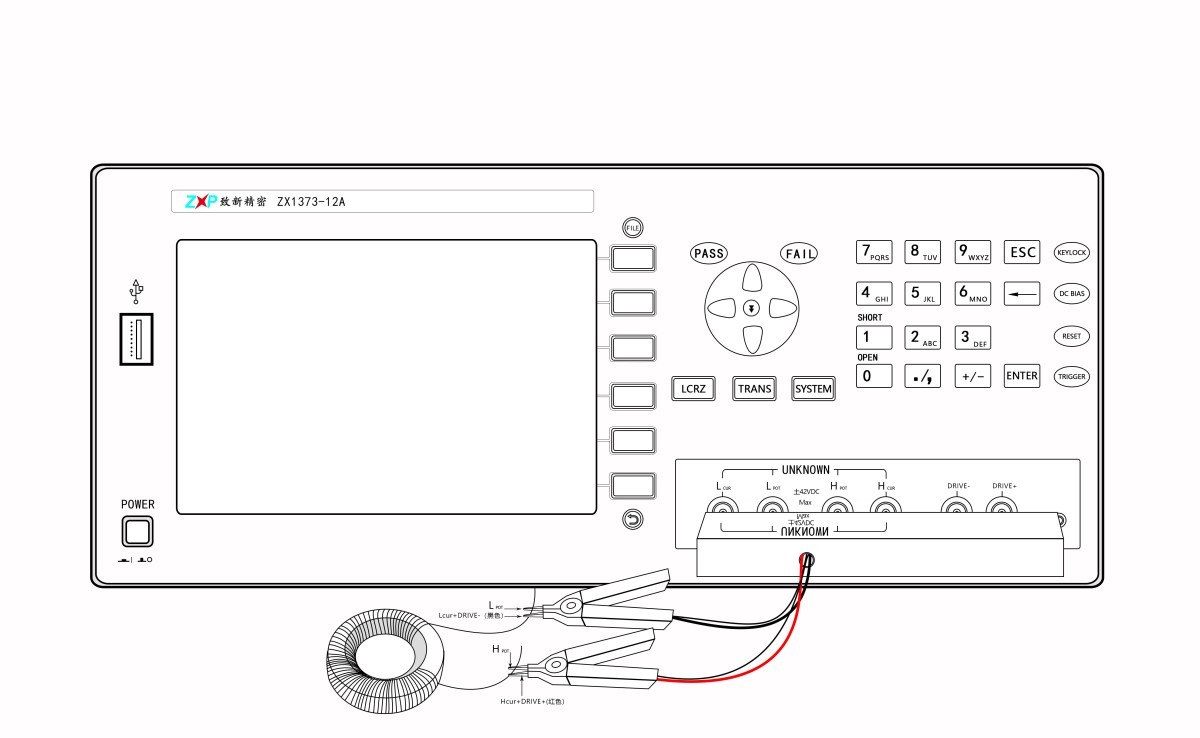
This test cable combines the DC and AC current terminals into a single unit, which is soldered to the terminals of a 4-terminal clip for user convenience. However, because it is designed to handle high currents, this cable does not use shielded wire and is therefore not suitable for high frequencies. It is recommended that the test frequency not exceed 20 kHz.
The connection method for performing an open-circuit reset using the LS1373Y03 test cable is shown in the figure below:
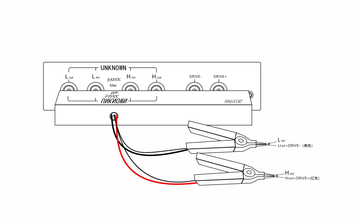
Generally, open-circuit zeroing is not required; however, when the impedance |Z| of the inductor under test exceeds 1 kΩ and the test requires high accuracy, open-circuit zeroing is necessary.
The connection method for performing a short-circuit reset using the LS1373Y03 test cable is shown in the figure below:
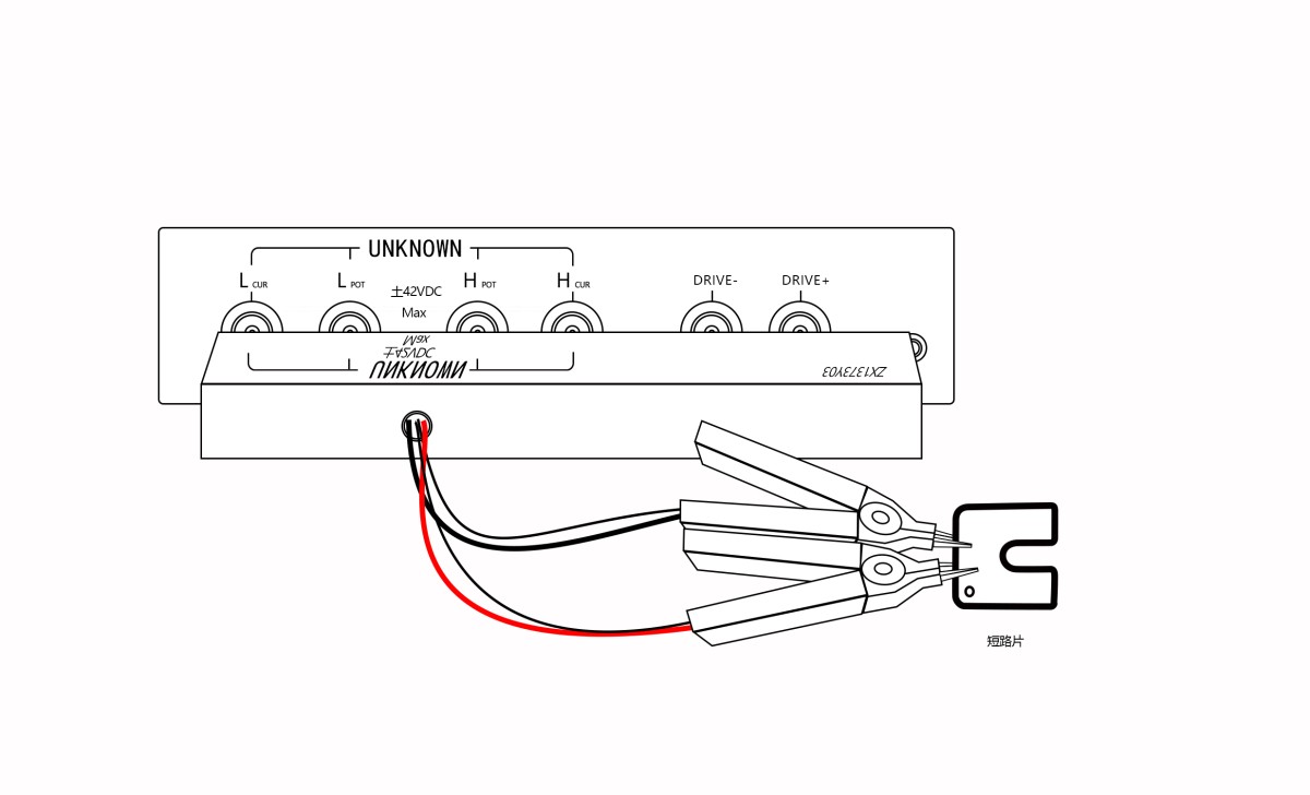
Generally, short-circuit zeroing is not necessary; however, when the impedance |Z| of the inductor under test is less than 10 Ω, short-circuit zeroing is required for tests with high accuracy requirements.
Note: When measurement stability of 10 nH is required, the short-circuit effect achieved by clamping the test probes together is not as effective as clamping them onto the two terminals of a gold-plated shorting pad that are positioned very close together.
5.1.1.2 Testing the Inductor Under Test Using a Cable Connection with LS28Y11 + LS1373Y02
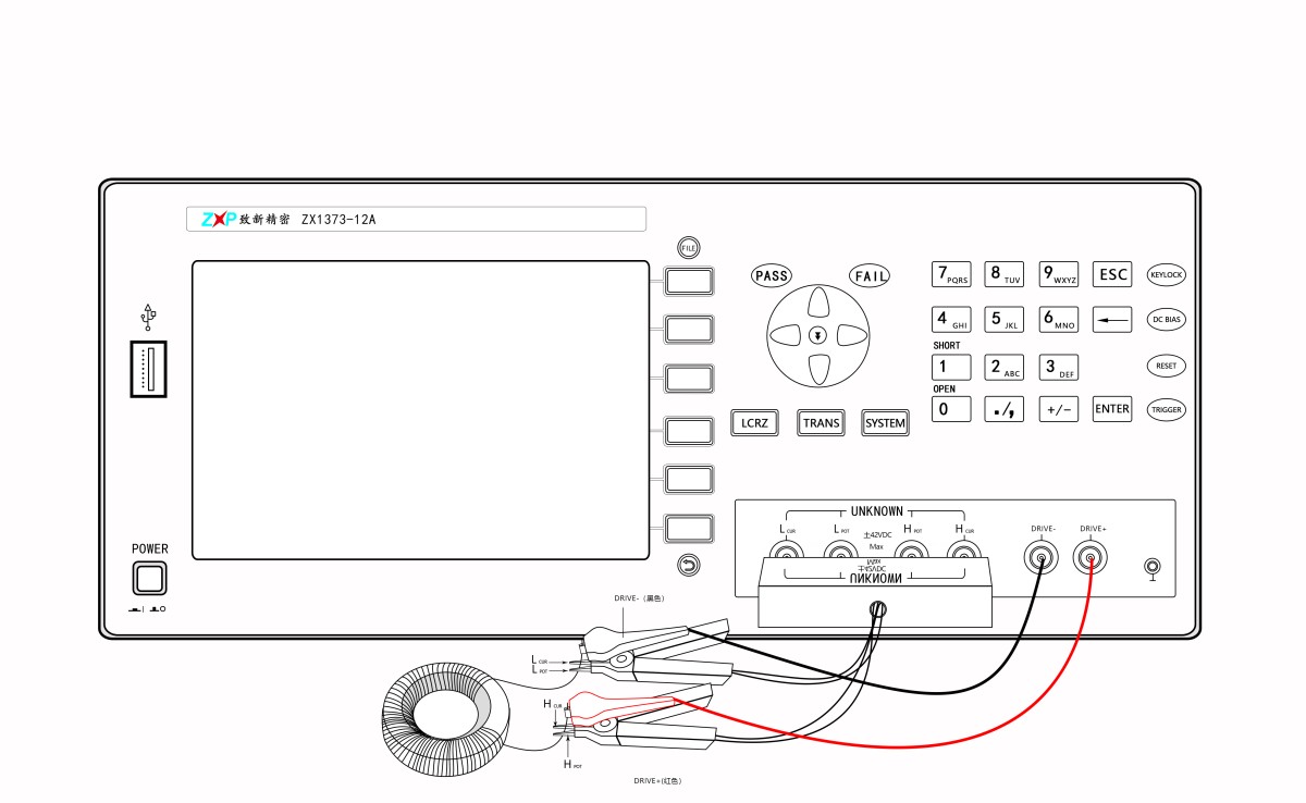
For this test connection method, use the LS1373Y02 test lead for applying current and the LS28Y11 LCR test cable separately; short-circuit both leads at the end of the inductor under test. Although this wiring method is slightly more complicated, it can be used for high-frequency testing. When the test frequency exceeds 20 kHz, this wiring configuration is recommended.
The connection method for performing an open-circuit reset using the LS28Y11+LS1373Y02 test cable is shown in the figure below:
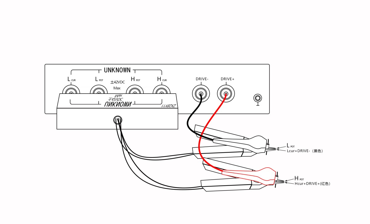
Generally, open-circuit zeroing is not necessary; however, when the impedance |Z| of the inductor under test exceeds 1 kΩ and the test requires a high degree of accuracy, open-circuit zeroing must be performed.
The connection method for short-circuit reset using the LS28Y11+LS1373Y02 test cable is shown in the figure below:
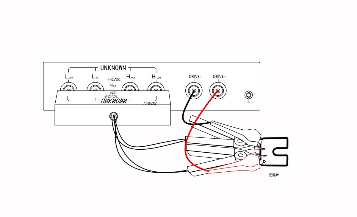
Generally, short-circuit zeroing is not necessary; however, when the impedance |Z| of the inductor under test is less than 10 Ω, short-circuit zeroing is required for tests with high accuracy requirements.
Note: When measurement stability of 10 nH is required, the short-circuit effect achieved by clamping the test probes together is not as effective as securing the test probes in a fixed position where the two clamps are very close to each other on the gold-plated shorting pad.
5.1.1.3 Testing Non-Inductive Components Using the LCR Bridge Function of the LS1373
When users wish to test non-inductive components, such as resistors or capacitors, using the LCR bridge function of the LS1373 alone, they must connect the resistor or capacitor under test to the LS28Y11 separately. They should not simultaneously apply DC bias current through the DRIVE+ and DRIVE- terminals, to prevent the superimposed current from affecting measurement accuracy.
Please refer to the figure below:
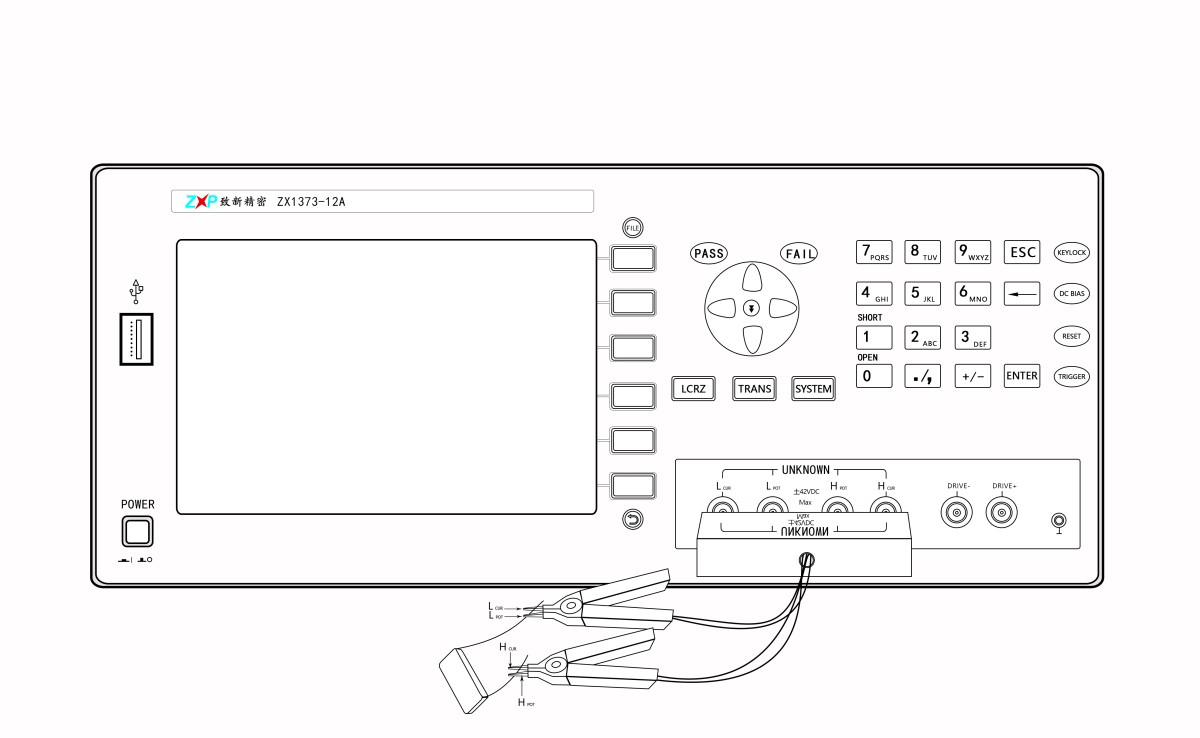
★ Note: When using the bridge function to test resistors and capacitors, do not connect the DRIVE+ and DRIVE- terminals for the DC bias current.
5.2 Operating the Main Functions
5.2.1 Bias Current
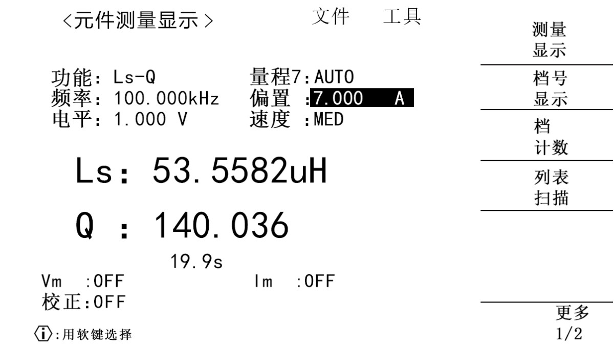
In the “Component Measurement Display” page’s bias section, users can set the desired DC bias current.
The specific parameters for the DC bias current of the LS1373 are shown in the table below:
| Current Range | Current Range | -12A to 12A | -12A to 12A | -12A to 12A |
| Current Accuracy | Current Accuracy | ±1% ±5 mA | ±1% ±5 mA | ±1% ±5 mA |
| Current | Measurement Range | 0 mA to 0.5 A | 0.5 A to 2.5 A | 2.5 A–12 A |
| Current | Step-by-step | 0.125 mA | 0.625 mA | 3.125 mA |
5.2.2 Starting the Measurement with the Bias Current
After setting the bias current and other required test conditions, and connecting the device under test according to the test lead connection method described in the previous section, press the [DC BIAS] button on the front panel. The [DC BIAS] indicator will light up, indicating that the DC bias current is active.
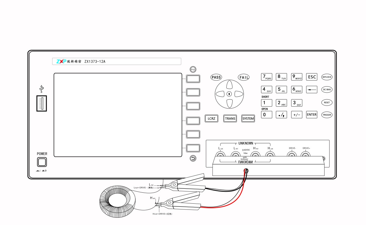
Once the measurement is complete, turn off the DC bias by pressing the [DC BIAS] button. The [DC BIAS] indicator will turn off, and the DC bias current will be turned off.
Offset Current Hold Time
Some inductors can overheat and burn out when subjected to high currents. The LS1373 can prevent this by controlling the current application time through the bias current hold time setting. For details, see the bias current hold time settings.
Auto-Renewal Feature
On the production floor, to improve testing efficiency, it is not desirable to turn the current on and off after testing each inductor. The LS1373 allows you to replace one inductor with another after the current terminal is open-circuited without having to press a button to turn the power off and then back on; the instrument automatically completes this process, making it convenient to use. This feature must be enabled on the < System Configuration> page.
5.2.3 Internal Resistance
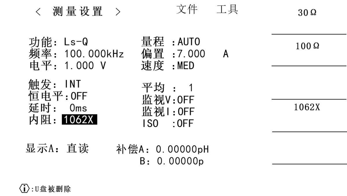
In the “Internal Resistance” section of the < Measurement Settings> page, users can set the source internal resistance for the desired LCR function.
The inductance of many inductors depends on frequency and on the magnitude of the AC current flowing through the inductor during measurement. Once the measurement frequency and level are fixed, the value of the inductance is determined by the source impedance. To facilitate data comparison with instruments from other manufacturers on the market, the LS1373 offers three internal resistance modes, as detailed in the table below:
| Internal Resistance Mode | Primary Comparison Instruments |
| 30 Ω | *8511D* |
| 100 Ω | *4284A, *4980A |
| 1062X | *1062* |
The instrument is set to 1062X mode by default; this mode provides better stability for superimposed current testing.
However, the 1062X mode supports frequencies up to a maximum of 300 kHz; for frequencies above 300 kHz, we recommend using the 30 Ω internal resistance mode.
5.2.4 Offset Current List Scan Settings
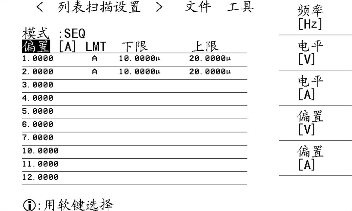
On the < List Scan Settings> page, users can select and configure DC bias current scanning.
5.2.5 Offset Current List Scan Display
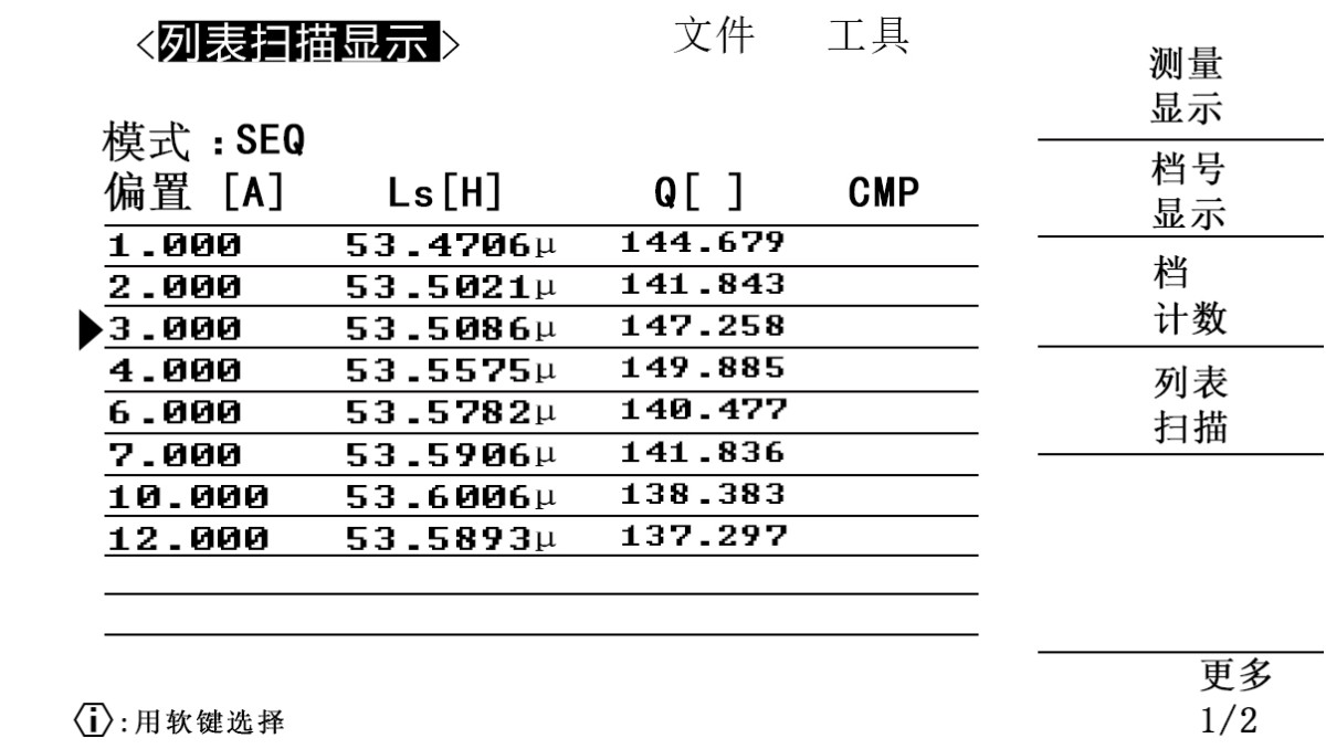
On the < List Scan Settings> page, after the user selects and configures a DC bias current scan, they proceed to the < List Scan Display> page. When the [DC BIAS] button is pressed to apply the current, the instrument automatically performs a sequential current scan and measurement according to the current settings previously configured by the user.
5.2.6 Automatic Flow Resumption Feature:
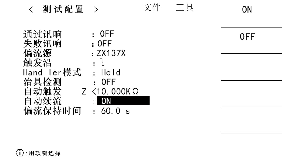
In the “Automatic Flow Resumption” section of the < Test Configuration> page, users can enable or disable the instrument’s automatic flow resumption feature.
Feature Description: On the production floor, to improve testing efficiency, it is undesirable to have to turn the current on and off each time a new inductor is tested. The LS1373 automatically handles this process—when the current terminal is open-circuited and another inductor is inserted—without requiring the user to press a button to turn the current off and then back on, making it convenient to use.
OFF
When “Auto Renew” is set to OFF, on the measurement display page, with DC BIAS enabled, if the instrument’s current drive terminal is open-circuited, the instrument will automatically cut off the current output relay and disable DC BIAS.
ON
When the Auto Hold setting is set to ON, on the measurement display screen, with DC BIAS enabled, if the instrument’s current drive terminal is open-circuited, the instrument will not automatically deactivate the current output relay or turn off DC BIAS. Instead, it will automatically adjust the drive current to a value close to 0 A. When the user reconnects the inductor under test, the instrument will automatically adjust the output current to the user-set value.
In addition, when the test clamps are open, the instrument displays “OVER LOAD,” indicating that the current source is overloaded and the measurement cannot proceed normally.
5.2.7 Setting the Offset Current Hold Time:
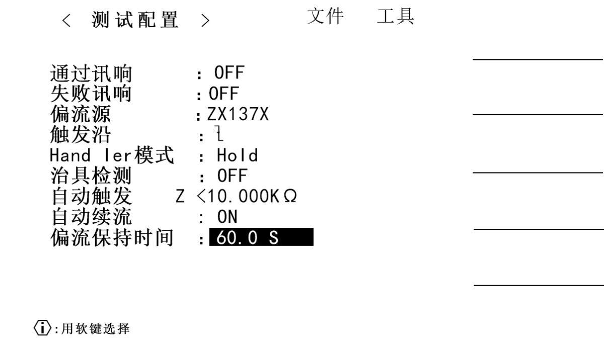
In the “Current Hold Time” section of the < Test Configuration> page, users can set the current hold time. If set to “0,” the instrument assumes this feature is not in use.
Function Description: Some inductors can overheat and burn out when a high current is applied. The LS1373 can control the duration of current application by setting the bias current hold time, thereby preventing such issues.
5.2.8 Open-Circuit and Short-Circuit Reset Function:
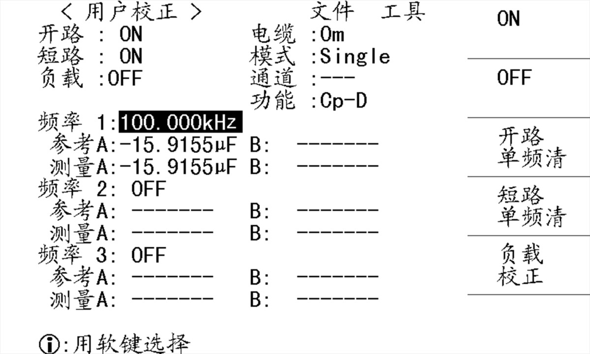
When the impedance |Z| of the inductor under test exceeds 1 kΩ, or when the test requires a high degree of accuracy, an open-circuit zeroing procedure is necessary.
The method for opening the circuit varies depending on the type of fixture; please refer to the descriptions in the previous sections.
When the impedance |Z| of the inductor under test is less than 10 Ω, or when the test requires a high degree of accuracy, a short-circuit zeroing procedure must be performed.
The short-circuiting method varies depending on the type of fixture; please refer to the descriptions in the previous sections.
LS1373 recommends using [Open-Circuit Single-Frequency Clear] and [Open-Circuit Single-Frequency Clear] to clear open-circuit and short-circuit conditions.
5.2.9 Common Steps for Measuring Current Through an Inductor:
1. Turn on the power
2. Set the measurement conditions
3. Perform open-circuit and short-circuit calibration based on the impedance of the inductor under test
4. Connect the inductor under test to the test clamps.
5. Turn on the DC bias output
6. View the measurement results on the measurement page
7. Turn off the DC bias output.
5.3 Command Reference
This instrument allows you to control the current level, set the startup current, and check the instrument’s status using SCPI commands via the RS232C interface. The relevant commands are as follows:
5.3.1: BIAS: CURRENT
Syntax: BIAS: CURRent < numeric>
: BIAS: CURRent ?
This setting configures the DC bias current. Setting this value does not mean that the DC bias is enabled. Because this series of instruments offers a high degree of flexibility, the instrument does not strictly verify whether the current value set by the user is valid. Please note this.
Parameters
| < Numeric> | |
| Scope | -12 to 12 |
| Unit | A |
5.3.2: BIAS: STATe
Syntax: BIAS: STATE {ON|OFF|1|0}
: BIAS: STATe?
Describes the activation of DC bias. DC bias is automatically turned off after the state is loaded from memory. When DC bias is set to ON, the output provides the DC bias set by : BIAS: CURRent.
Parameters
| Description | |
| ON or 1 | Enable DC Offset |
| OFF or 0 | Disable DC Offset |
5.3.3: BIAS: ERROR
Syntax: BIAS: ERROR?
Describes the current error status of the query bias source.
Parameters
| Description | |
| 0 | No errors occurred |
| 1 | OVERLOAD or UNBAL |
| 2 | OVERLOAD |
| 3 | UNBAL |
6. HANDLER Interface User Guide
The instrument provides users with a Handler interface, which makes it easy to build an automated component sorting system. When the instrument is used in an automated component sorting and testing system, this interface provides signals for interacting with the system and for outputting sorting results.
6.1 Definition of the HANDLER Interface
Output Signal Specifications: Low-level active, open-collector output, optically isolated.
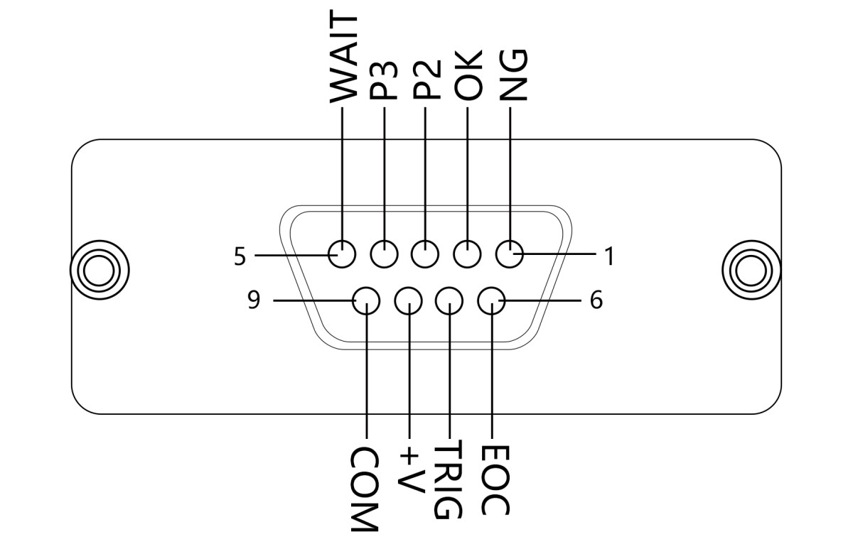
Handler Interface Definition
The flowchart for Bin Sorting when sorting into three bins is shown in the figure:
Definition of 3-Level Sorting Signals
| Foot position | Features |
| 1 | /NG (D/QNG) is a non-pass signal; the output is active low. |
| 2 | /P1 is a first-class product that meets specifications; the output is low and valid. |
| 3 | /P2 indicates a second-grade合格 product with low output effectiveness |
| 4 | /P3 is a Grade 3合格 product with low output effectiveness |
| 5 | WAIT (Busy) output, active-high. This signal can be used to control the operation of external mechanical processing equipment during instrument testing; when this signal is active, the instrument is performing measurements and calculations. |
| 6 | /EOC (A/D End): Output, active low. When this signal is output, the measurement (A/D conversion) of the current device under test has been completed, although calculations may still be in progress. When this output is high, good contact between the test terminals and the current device under test must be ensured; when it is low, external mechanical equipment is permitted to move the next test device to the test terminals in preparation for the next measurement. |
| 7 | /START (Start): Input; valid only if it is a falling edge and the low-level duration is greater than 2.5 ms. This signal is supplied externally to the HANDLER input. |
| 8 | EXTV External Input Power Supply (The instrument is connected to the external power source by default) |
| 9 | Low-side output of the COM interface |
Signal Mapping Chart for the DB9 Socket Connector of the Handler Interface
The instrument’s operating sequence is shown in the figure below:
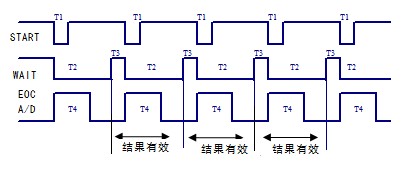
Instrument Timing Diagram
T1: The duration of the START signal must be greater than 2.5 ms. Instrument measurement begins when the STARTU signal transitions from high to low, and the signal must be removed before T2 returns to low; otherwise, another measurement may be triggered erroneously. If no external START signal is present, pressing the start button on the instrument’s front panel will also generate a start signal.
T2: The instrument’s measurement and calculation time; at the end of T2, the sorting results are sent to the HANDLER interface.
T3: The wait time from when WAIT is inactive to when START is active. Determined by the mechanical transmission mechanism.
T4: Instrument A/D conversion time.
As shown in the figure, the valid interval for outputting the measurement and sorting results for each component is the period from the end of the current T2 to the end of the next T2.
6.2 Wiring Between the Instrument and the PLC
Generally speaking, the necessary drive circuits are already built into both the instrument and the PLC; all the user needs to do is connect the 24V, 0V, and any required signal lines.
7. Packing List
| 1 | LS1373 Host | 1 |
| 2 | Spare fuse (2A) | 2 |
| 3 | LS28Y11 Test Line | 1 |
| 4 | LS1373Y03 Test Line | 1 |
| 5 | Power Cord | 1 |
| 6 | CD-ROM (containing the electronic user manual, warranty card, certificates, etc.) | 1 |