
 English
 中文简体
中文简体 English
 Русский
 Español
 Português
 Türkçe
 العربية
 Deutsch
 Polski
 Italiano
 Français
 한국어
한국어 ไทย
ไทย Tiếng Việt
 日本語
日本語





























Photo And Electric Tester
User's Manual
Applicable LISUN models: LS616S
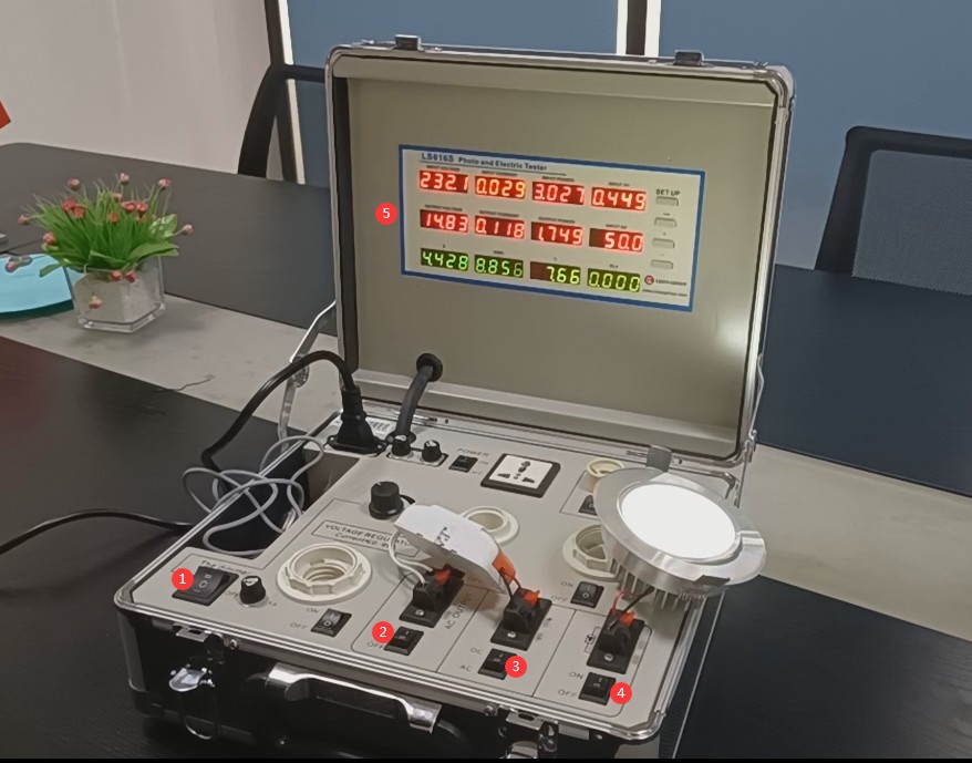
Power Cord Connection, = 1 * GB3① Connect the device to the correct power source. = 2 * GB3② Then turn on the device.
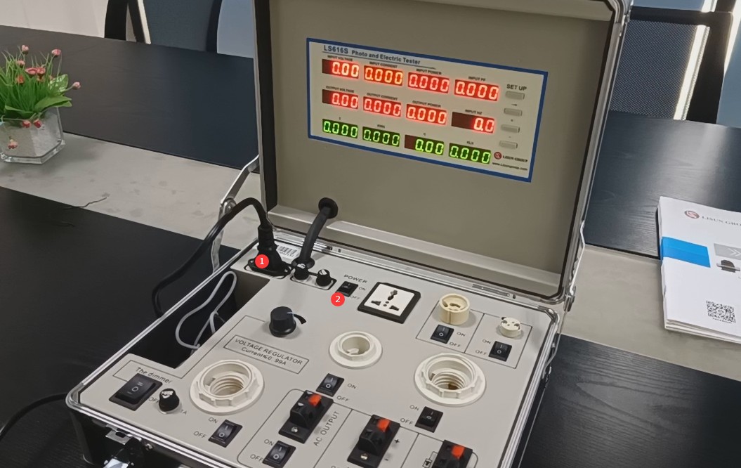
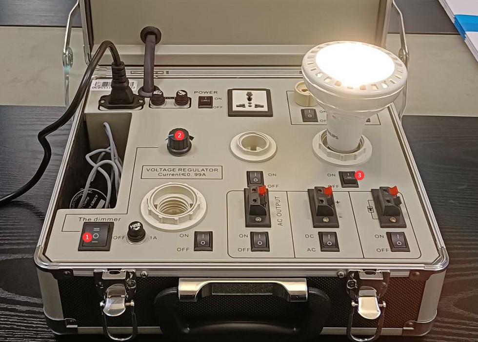
The equipment power cord supplies power to both the equipment and the sample. = 1 * GB3① The three-position switch is used to control the sample power supply. The top position functions as a Voltage Regulator; when switched to this position, you can use the Voltage Regulator at = 2 * GB3② to adjust the sample input voltage. The middle position is “Off”; set it to this position to turn off the sample’s power supply. The lower position provides direct power; when set to this position, the sample is powered directly by the voltage from the Input power supply. = 3 * GB3③ Additionally, each sample mounting location has a separate switch to control power to that specific sample.
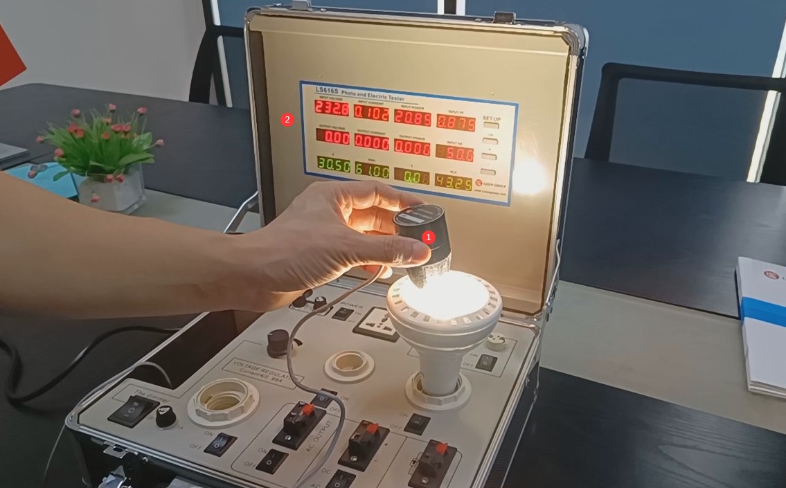
= 1 * GB3① Simply use the probe to test the parameters at the desired location. = 2 * GB3② All parameters are displayed on the upper screen.
If you need to test the input and output parameters of the LED driver, connect the wires as shown in the figure below. = 1 * Connect the AC input of the LED driver to GB3①. = 2 * Connect the DC output of the LED driver to GB3②. = 3 * Connect the LED light source to GB3③. Note: = 2 * GB3② = 3 * GB3③—Do not reverse the positive and negative terminals.
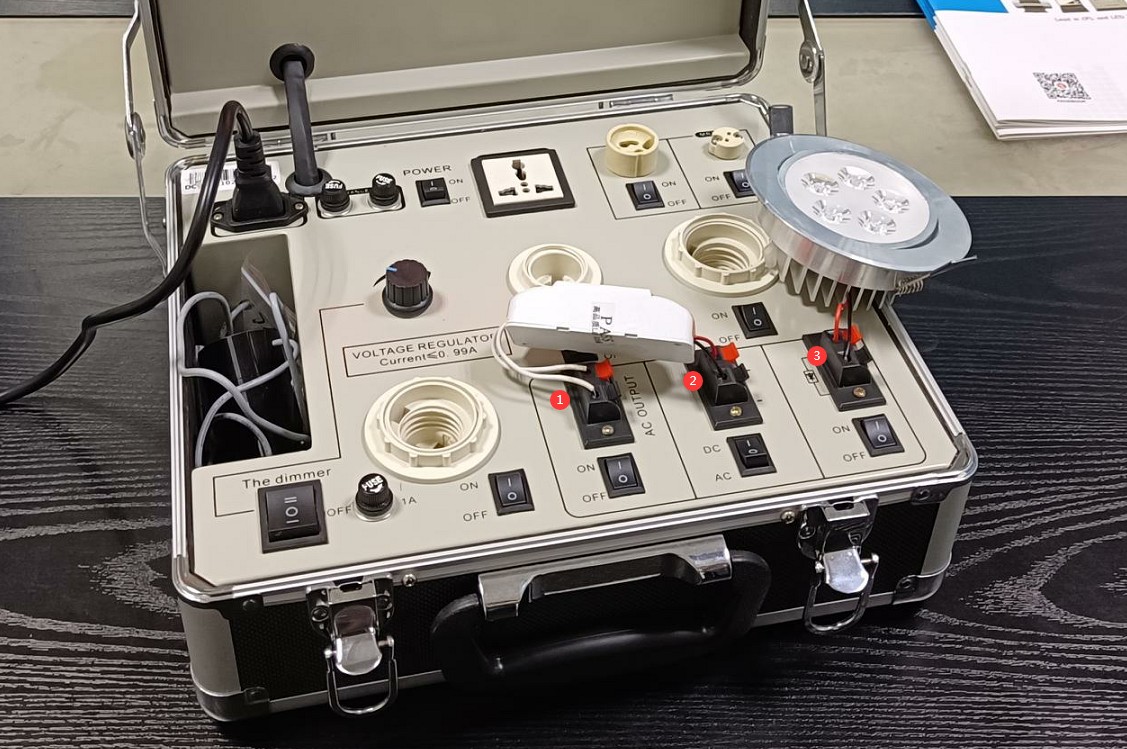
= 1 * GB3① Turn on the three-position switch. = 2 * GB3② Turn on the LED driver input switch. = 3 * GB3③ Set this switch to the DC side. = 4 * GB3④ Turn on the LED light source switch. = 5 * GB3⑤ You can now view the input and output parameters of the LED driver.
LED Luminaires and LED Power Driver Test Solution
Goniophotometer System: LSG-6000, LSG-1890B, or LSG-1700
Spectroradiometer & Integrating Sphere Test System: LPCE-2 or LPCE-3
LED Life Maintains a Test System in Accordance with LM-80: LEDLM-80PL
Waterproof Test for IPX5 and IPX6 Levels: JL-56
Dustproof Testing Machine for IP5X and IP6X Testing: SC-015
LED Power Driver Testers: LS2090 (for the lab) and ATE-2 (for the production line)
Electrical Safety Tester: LS9955
CFL and Electronic Ballast Test Solution
Goniophotometer System: LSG-1890B or LSG-1700
Integrating Sphere and Spectrophotometer Test System: LPCE-2 or LPCE-3
Adjustable Reference Ballast: DYJ-50HZ, HCS-109A, and DYJ-HID
Electric Ballast Tester: WT5000 (for the lab) and ATE-1 (for the production line)
Digital Torsion Meter and Multiway Life Tester: CH338 and CH316
Electrical Safety Testers: LS9923, ZRS-3H, ZY-3
EMC and EMI Test Solutions for CFL and LED Luminaires
EMI Test System: EMI-9KB or EMI-9KA
Electrostatic Discharge Simulator: ESD61000-2
EFT Immunity Measurement: EFT61000-4
Surge Generator: SG61000-5
Voltage Dips and Interruptions Generator: CSS61000-11
Ring Wave Generator: RWG61000-12

www. Lisungroup.com
Patents Filed
All Rights Reserved by Lisun Group
Subject to Change Without Notice