
 English
 中文简体
中文简体 English
 Русский
 Español
 Português
 Türkçe
 العربية
 Deutsch
 Polski
 Italiano
 Français
 한국어
한국어 ไทย
ไทย Tiếng Việt
 日本語
日本語





























CDM ESD Test System
User's Manual
Applicable LISUN models: ESD-CDM
The ESD-CDM is used for CDM electrostatic testing and is fully compliant with ANSI/ESDA/JEDEC JS-002-2014, “For Electrostatic Discharge Sensitivity Testing—Charged Device Model (CDM)—Device Level.”The system primarily consists of three components: a DC high-voltage source, a test host, and an electrostatic test probe (including an attenuator). It is capable of performing electrostatic induction charging, electrostatic discharge, and discharge signal acquisition tests on charged device models (CDMs).
Equipment Overview
Please open all packages and check the products against the packing list. If you notice any discrepancies, please contact us immediately.
Equipment Appearance:
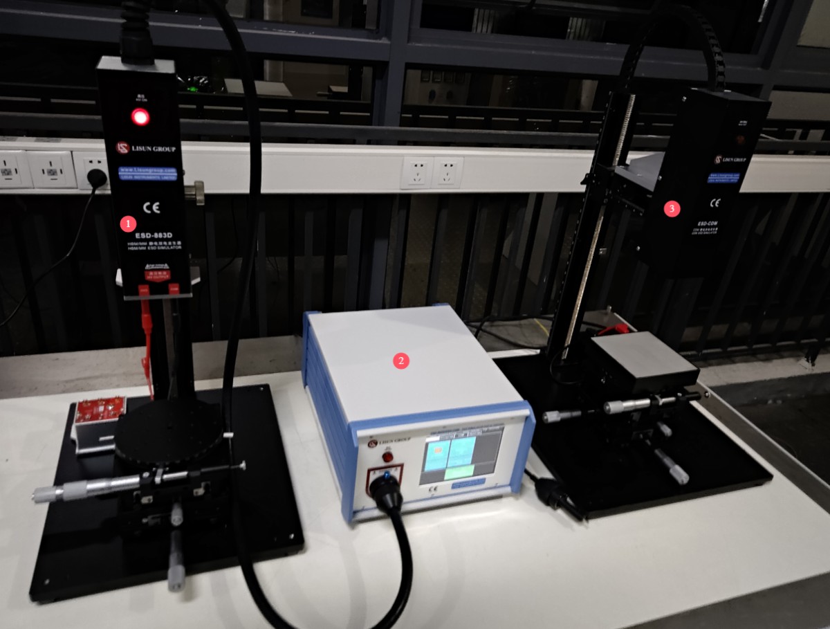
= 1 * GB3① HBM/MM discharge tower.
= 2 * GB3② ESD main unit.
= 3 * GB3③ CDM discharge tower.
Note: The HBM/MM module and the CDM module can share the same main unit. This model includes only the CDM module.
Instrument Front Panel:
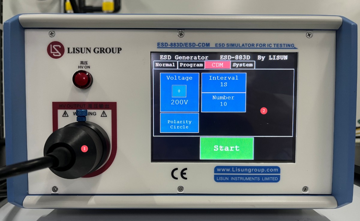
= 1 * GB3① Touchscreen LCD, used for setting and controlling discharge parameters.
= 2 * GB3② High-voltage sockets; the discharge tower’s high-voltage cables and control wires are connected to the main unit via these sockets. Ensure the high-voltage connectors are properly connected before turning on the instrument’s power. When inserting the high-voltage plug into the high-voltage socket, align it with the socket’s positioning pin, then gently push it all the way in and tighten the retaining cap. Note: Forcibly inserting the plug without aligning it with the positioning pin may damage the fine copper pins inside the high-voltage plug.
Rear Panel:
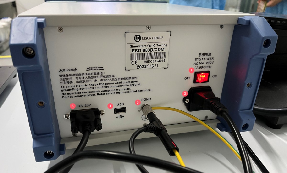
= 1 * GB3① Instrument power switch. = 2 * GB3② Power socket, with built-in fuse. = 3 * GB3③ RS232/RS485 communication port, for connecting to the CDM discharge tower.= 4 * GB3④ USB port, for connecting a mouse to control the touchscreen or a USB flash drive to upgrade the operating system. = 5 * GB3⑤ Grounding terminal; this terminal must remain properly grounded while the device is in use.
Discharge Tower:
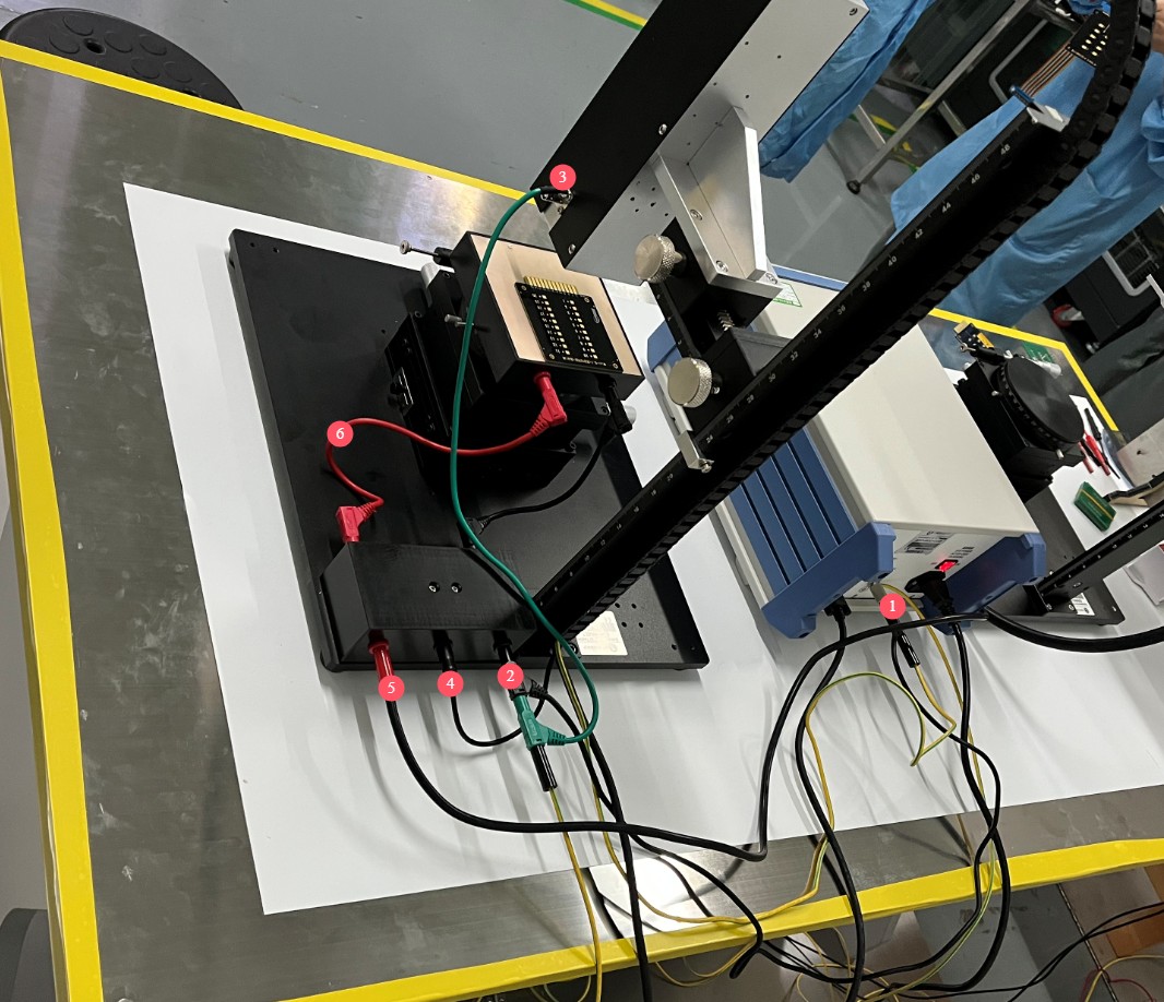
= 1 * GB3① = 2 * GB3② = 3 * GB3③ Ground connection: When the equipment is in use, these three grounding ports must be connected to ground.
= 4 * GB3④ Discharge tower control wire connection.
= 5 * GB3⑤ High-voltage electrostatic discharge cable; the other end connects to the main unit of the Electrostatic Discharge Simulator.
= 6 * GB3⑥ Red and black wires connect to the test bench.
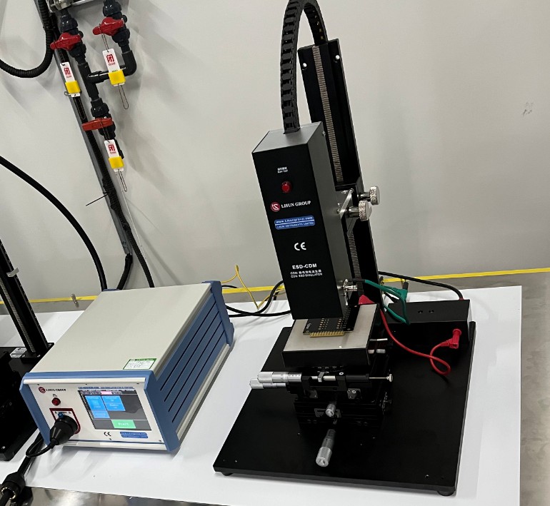
After the main unit and the discharge tower are connected, the setup will look as shown in the figure below:
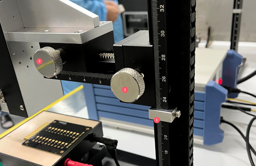
Adjust the discharge tower height according to the sample:
= 1 * GB3① Limit block—this is the lowest adjustable position of the discharge tower;
for safety reasons, do not adjust it any lower. = 2 * GB3② Rotate to adjust the height of the discharge tower.
= 3 * GB3③ Rotate to adjust the forward and backward position of the discharge tower.
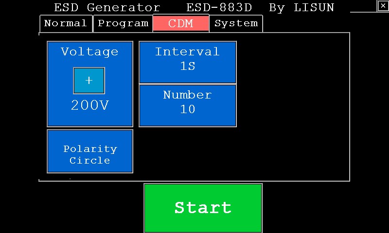
Program interface. You can set the electrostatic discharge voltage, polarity, interval time, number of discharges, and other parameters.
Equipment Operation
Complete all system wiring connections in accordance with the previous chapter and the relevant standards.
Install the test object and adjust the test stand, as well as the height and position of the discharge tower, according to the actual test object. You can first run a simulation test; the discharge tower will rise and lower automatically, and when it reaches its lowest point, it should make contact with the test point.
Set the test parameters in the program interface; once they are set, you can begin the test.
When the test is complete, replace the sample or shut down the machine.
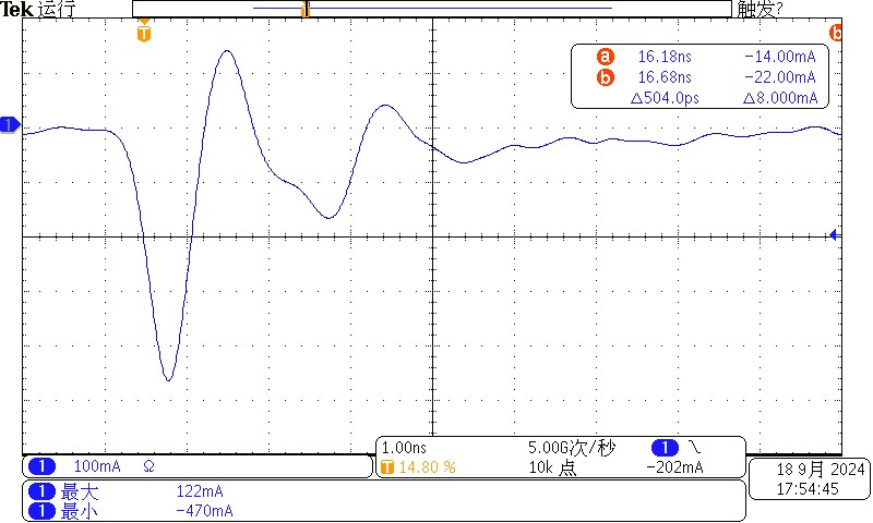
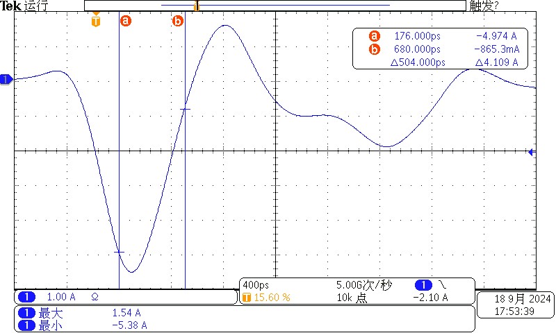
Discharge Waveform Diagram
Packing List
| 1 | ESD Host | 1 |
| 2 | CDM Discharge Tower | 1 |
| 3 | Power Cord | 1 |
| 4 | Coaxial Cable | 1 |
| 5 | High-Voltage Connecting Cables | 2 |
| 6 | Ground Wire | 2 |
| 7 | CD (includes a digital user manual, warranty card, certificates, etc.) | 1 |
Photometric, Colorimetric, and Safety Performance Testing Solutions for LEDs
Goniophotometer System: LSG-6000, LSG-1890B, or LSG-1800ACCD
Spectroradiometer & Integrating Sphere Test System: LPCE-2 or LPCE-3
LED Life Maintains a Test System in Accordance with LM-84: LEDLM-84PL
Photobiological Radiation Safety Test System: EN 62471-C or EN 62471-P
Lamp Start, Run-up Time, and Flicker Test System: LSRF-3 and LSP-500VARC-Pst
LED Power Driver Testers: LS2090, M9822, and LSP-500VARC
IK Level Tester | Spring Hammer Impact Tester: IK07-10, IK01-06
Electrodynamic Vibration Generator System: LVD-100KG-6D
Electrical Safety Testers: LS9955, ZRS-3H, ZY-3, TTC-1
Environmental Chamber Test Solution for LED Luminaires
Waterproof Test for IPX5 and IPX6: JL-56
Dustproof Testing Machine for IP5X and IP6X: SC-015
High- and Low-Temperature and Humidity Chamber: GDJS-015B
Salt Spray Test Machine: YWX/Q-010
UV Lamp Aging Test Chamber: UV-263LS
Xenon Lamp Aging Test Chamber: XD-80LS
Ozone Test Chamber: OTC-150A
Sulfur Dioxide Test Chamber: SQ-010
EMC and EMI Test Solutions for CFL and LED Luminaires
EMI Test System: EMI-9KB or EMI-9KA
Electrostatic Discharge Simulator: ESD61000-2
EFT Immunity Measurement: EFT61000-4
Surge Generator: SG61000-5
Voltage Dips and Interruptions Generator: CSS61000-11
Ring Wave Generator: RWG61000-12

www. Lisungroup.com
Patents Filed
All Rights Reserved by Lisun Group
Subject to Change Without Notice