
 English
 中文简体
中文简体 English
 Русский
 Español
 Português
 Türkçe
 العربية
 Deutsch
 Polski
 Italiano
 Français
 한국어
한국어 ไทย
ไทย Tiếng Việt
 日本語
日本語





























Adjustable Reference Ballast For HID
User's Manual
Applicable LISUN models: DYJ-HID-50HZ、DYJ-HID-60HZ
1. Introduction
This high-intensity gas-discharge lamp multi-purpose reference ballast is designed and manufactured in accordance with the requirements of GB/T 21093 (IEC 60188), GB/T 13259 (IEC 60662), and GB/T 18661 (ANSI C78.43).
This multi-purpose reference ballast for high-intensity gas discharge lamps is available in two specifications—50 Hz and 60 Hz—and can be used in different countries and regions around the world. It can be used to test the luminous efficacy of high-pressure mercury lamps, as well as the lumen factors of various ballasts used with these high-intensity gas discharge lamps (ballast energy efficiency testing).
Basic Parameters and Specifications of Reference Ballasts:
1 Current range for the reference ballast: 0.300 A to 10.50 A;
2 Impedance range for the reference ballast: 16.8 Ω to 390 Ω;
3 Error range of the reference ballast impedance at the calibration current: ≤±0.5%.
4 The error range for the reference ballast impedance at any current between 50% and 115% is: ≤±3.0%.
This high-intensity gas-discharge lamp, when used with a standard ballast, meets all relevant requirements of the aforementioned standards.
2. Instructions for Use
2.1. Measurement of Photometric Parameters of High-Intensity Gas-Discharge Lamps
The photometric parameters of a high-intensity gas-discharge lamp were measured using the connection shown in Figure 1.
The procedure is as follows:
Based on the wattage and model of the lamp being tested, identify the parameters required for testing from the standards listed above or from Tables 1, 2, or 3 attached hereto, including the supply voltage and the impedance value of the reference ballast.
(2) Place the lamp to be measured inside the Integrating Sphere and connect the measurement circuit as shown in Figure 1.
(3) Based on the power rating of the reference ballast and the lamp model, locate the corresponding knob switch adjustment positions in Table 1, Table 2, or Table 3 based on the power rating of the reference ballast and the lamp model. Adjust the six knobs on the multi-purpose reference ballast to the positions specified in Table 1, Table 2, or Table 3. At this point, all parameters of the high-intensity gas discharge lamp reference ballast will meet the requirements for reference ballasts specified in the corresponding standards.
Note: Be sure to adjust the six rotary switches on the multi-purpose reference ballast to the positions specified in Table 1, Table 2, or Table 3, based on the power rating of the reference ballast and the lamp model you have identified, before connecting the power supply.
(4) Adjust the power supply voltage and frequency to the required values, and connect the power supply to the “Power Supply” terminal in the circuit shown in Figure 1 to start the lamp (for high-pressure sodium lamps and metal halide lamps, a suitable igniter must be connected across the lamp terminals to start the lamp).
(5) After the lamp has stabilized for 25 to 30 minutes (determine whether the lamp’s photometric parameters have stabilized based on the stability of the luminous flux and lamp power parameters), measure the lamp voltage, current, and power.
2.2. Testing the Lumen Efficiency of Ballasts for High-Intensity Gas Discharge Lamps
The luminous efficiency test of ballasts for high-intensity gas discharge lamps is performed using the connection shown in Figure 2.
The procedure is as follows:
Based on the power rating and model of the lamp paired with the ballast under test, refer to Tables 1, 2, or 3 attached below to identify the parameters required for testing, including the supply voltage and the impedance value of the reference ballast.
Install the reference lamp inside the Integrating Sphere or in a darkroom. Connect the measurement circuit as shown in Figure 2.
Based on the rated power of the reference ballast and the lamp model you have determined, locate the corresponding adjustment switch positions in Table 1, Table 2, or Table 3, and adjust the six rotary switches on this multi-purpose reference ballast to the positions specified in Table 1, Table 2, or Table 3. At this point, all parameters of this high-intensity gas discharge lamp reference ballast will meet the requirements for reference ballasts specified in the corresponding standards.
Note: Be sure to adjust the six rotary switches on the multi-purpose reference ballast to the positions specified in Table 1, Table 2, or Table 3, based on the power rating of the reference ballast and the lamp model you have identified, before connecting the power supply.
Set switch S1 to the circuit of the ballast under test (upward position as shown in the figure). Turn on the power supply for the ballast under test, adjust the supply voltage to the rated voltage of the ballast, and start the lamp (for high-pressure sodium lamps and metal halide lamps, a suitable igniter must be connected across the lamp terminals to start the lamp). After the lamp has stabilized for 25 to 30 minutes (when the photometer or Pocket Illuminance Meter readings have stabilized), record the light output value of the ballast under test.
Turn on the power supply for the reference ballast and adjust the supply voltage to the rated voltage of the reference ballast.
Quickly switch S1 to the reference ballast circuit (the downward position shown in the figure); at this point, the lamp should still be in the glow-in-start state (if the lamp goes out during the switch, you can restore the glow by repeatedly closing and opening the start switch S2). Fine-tune the power supply voltage for the reference ballast to reach the test voltage value specified in the standard. After stabilizing for 5 to 30 minutes, record the light output value of the reference ballast.
Calculate the lumen factor using the formula: lumen factor = light output of the ballast under test / light output of the reference ballast.
3. Parameter Settings and Wiring Diagrams
Tolerances and Knob Configurations for Various Specifications of High-Pressure Mercury Lamp Reference Ballasts
Table 1
| Standard Requirements | Standard Requirements | Standard Requirements | Actual Measurements | Actual Measurements | Knob Configuration | Knob Configuration | Knob Configuration | Knob Configuration | Knob Configuration | Knob Configuration | |
| Power (W) | Calibration Current (A) | Impedance (Ω) | COS∮ | Impedance Error (%) | COS∮ | A | B | C | D | E | F |
| 50 | 0.62 | 297 | 0.075 | -0.01 | 0.075 | 8 | 0 | 0 | 6 | 4 | 4 |
| 80 | 0.80 | 206 | 0.075 | -0.01 | 0.075 | 8 | 8 | 2 | 6 | 0 | 2 |
| 125 | 1.15 | 134 | 0.075 | +0.02 | 0.074 | 1 | 6 | 6 | 4 | 2 | 2 |
| 175 | 1.50 | 99.5 | 0.075 | +0.01 | 0.076 | 8 | 1 | 9 | 4 | 3 | 0 |
| 250 | 2.15 | 71 | 0.075 | -0.01 | 0.076 | 5 | 3 | 4 | 2 | 5 | 0 |
| 400 | 3.25 | 45 | 0.075 | +0.11 | 0.076 | 2 | 7 | 6 | 2 | 3 | 0 |
| 1000 | 7.50 | 18.5 | 0.040 | -0.09 | 0.039 | 0 | 1 | 6 | 0 | 1 | 0 |
Tolerances and Knob Configurations for Various Specifications of High-Pressure Sodium Lamp Reference Ballasts
Table 2
| Standard Requirements | Standard Requirements | Standard Requirements | Actual Measurements | Actual Measurements | Knob Configuration | Knob Configuration | Knob Configuration | Knob Configuration | Knob Configuration | Knob Configuration | |
| Power (W) | Calibration Current (A) | Impedance (Ω) | COS∮ | Impedance Error (%) | COS∮ | A | B | C | D | E | F |
| 35 | 0.53 | 353 | 0.075 | -0.01 | 0.075 | 5 | 5 | 3 | 6 | 4 | 5 |
| 50 | 0.76 | 246 | 0.075 | -0.02 | 0.075 | 2 | 8 | 1 | 6 | 0 | 4 |
| 70 | 0.98 | 188 | 0.075 | +0.02 | 0.075 | 7 | 0 | 0 | 5 | 4 | 2 |
| 100 | 1.20 | 148 | 0.060 | -0.03 | 0.060 | 8 | 0 | 7 | 2 | 0 | 1 |
| 110 | 1.10 | 134 | 0.060 | -0.03 | 0.061 | 6 | 6 | 6 | 2 | 0 | 1 |
| 150 | 1.80 | 99 | 0.060 | -0.03 | 0.059 | 8 | 1 | 5 | 2 | 0 | 0 |
| 250 | 3.00 | 60 | 0.060 | -0.05 | 0.060 | 4 | 2 | 6 | 1 | 3 | 0 |
| 400 | 4.60 | 39 | 0.060 | -0.11 | 0.060 | 2 | 1 | 8 | 1 | 2 | 0 |
| 1000 | 10:30 | 16.8 | 0.040 | -0.20 | 0.040 | 4 | 0 | 0 | 0 | 2 | 0 |
Errors and Knob Configurations for Various Specifications of Reference Ballasts for Metal Halide Lamps
Table 3
| Standard Requirements | Standard Requirements | Standard Requirements | Actual Measurements | Actual Measurements | Knob Configuration | Knob Configuration | Knob Configuration | Knob Configuration | Knob Configuration | Knob Configuration | |
| Power (W) | Calibration Current (A) | Impedance (Ω) | COS∮ | Impedance Error (%) | COS∮ | A | B | C | D | E | F |
| 35 | 0.53 | 350 | 0.075 | -0.01 | 0.075 | 5 | 2 | 4 | 6 | 3 | 5 |
| 50 | 0.68 | 272 | 0.075 | -0.01 | 0.075 | 5 | 4 | 5 | 6 | 2 | 4 |
| 70 | 0.90 | 188 | 0.075 | +0.01 | 0.074 | 7 | 0 | 0 | 5 | 3 | 2 |
| 100 | 1.10 | 157 | 0.075 | +0.03 | 0.076 | 3 | 9 | 4 | 4 | 5 | 2 |
| 150 | 1.80 | 97 | 0.075 | +0.05 | 0.076 | 7 | 8 | 6 | 4 | 3 | 0 |
| 175 | 1.50 | 102 | 0.075 | -0.01 | 0.075 | 8 | 4 | 3 | 4 | 3 | 0 |
| 250 | 2.10 | 74 | 0.075 | -0.04 | 0.076 | 5 | 6 | 3 | 3 | 3 | 0 |
| 400 | 3.25 | 45 | 0.075 | +0.11 | 0.076 | 2 | 7 | 6 | 2 | 3 | 0 |
| 1000 | 4.10 | 79 | 0.075 | -0.04 | 0.074 | 6 | 2 | 2 | 3 | 4 | 0 |
| 1500 | June 20 | 50.2 | 0.075 | -0.05 | 0.075 | 3 | 3 | 2 | 2 | 3 | 0 |
Tolerances and Knob Settings for Linear Reactors Used in the Restart of Metal Halide Lamps by Specification
Table 4
| Standard Requirements | Standard Requirements | Standard Requirements | Actual Measurements | Actual Measurements | Knob Configuration | Knob Configuration | Knob Configuration | Knob Configuration | Knob Configuration | Knob Configuration | |
| Power (W) | Calibration Current (A) | Impedance (Ω) | COS∮ | Impedance Error (%) | COS∮ | A | B | C | D | E | F |
| 50 | 0.77 | 390 | 0.075 | -0.01 | 0.075 | 9 | 2 | 6 | 7 | 4 | 5 |
| 70 | 1.28 | 234 | 0.075 | -0.01 | 0.076 | 6 | 7 | 4 | 6 | 5 | 3 |
| 100 | 1.50 | 200 | 0.075 | +0.01 | 0.075 | 8 | 3 | 4 | 6 | 3 | 2 |
| 150 | 2.50 | 120 | 0.075 | +0.02 | 0.075 | 5 | 4 | 6 | 4 | 3 | 1 |
| 175 | 1.90 | 179 | 0.075 | -0.02 | 0.074 | 6 | 3 | 9 | 5 | 5 | 2 |
| 250 | 2.50 | 136 | 0.075 | -0.01 | 0.075 | 7 | 0 | 1 | 4 | 5 | 1 |
| 400 | 4.00 | 87.5 | 0.075 | +0.01 | 0.076 | 7 | 0 | 2 | 3 | 5 | 0 |
| 1000 | 5.70 | 77.4 | 0.075 | +0.07 | 0.074 | 6 | 1 | 8 | 3 | 4 | 0 |
| 1500 | 7.60 | 57.9 | 0.075 | +0.09 | 0.073 | 4 | 1 | 9 | 2 | 4 | 0 |
Impedance Error of Reference Ballasts at 50% and 115% of the Rated Current for Each Specification
Table 5
| Reference Ballast for High-Pressure Mercury Lamps | Reference Ballast for High-Pressure Mercury Lamps | Reference Ballast for High-Pressure Sodium Lamps | Reference Ballast for High-Pressure Sodium Lamps | Reference Ballast for Metal Halide Lamps | Reference Ballast for Metal Halide Lamps | Linear Reactors for Restarting Metal Halide Lamps | Linear Reactors for Restarting Metal Halide Lamps | |
| Power (W) | Impedance Error (%) | Impedance Error (%) | Impedance Error (%) | Impedance Error (%) | Impedance Error (%) | Impedance Error (%) | Impedance Error (%) | Impedance Error (%) |
| Power (W) | 50% | 115% | 50% | 115% | 50% | 115% | 50% | 115% |
| 35 | -1.02 | +0.04 | -0.99 | +0.03 | ||||
| 50 | -0.88 | +0.07 | -0.45 | -0.10 | -0.73 | -0.01 | -0.44 | -0.08 |
| 70 | -0.37 | -0.05 | -0.54 | -0.01 | +0.38 | -0.38 | ||
| 80 | -0.71 | +0.01 | ||||||
| 100 | -0.47 | -0.11 | -0.01 | -0.20 | +0.48 | -0.37 | ||
| 110 | -0.53 | -0.07 | ||||||
| 125 | +0.25 | -0.28 | ||||||
| 150 | -0.33 | -0.13 | -0.27 | -0.03 | +1.70 | -1.24 | ||
| 175 | -0.54 | -0.01 | -0.55 | -0.04 | +1.36 | -0.78 | ||
| 250 | -0.24 | -0.07 | +0.18 | -0.22 | -0.26 | -0.12 | +1.52 | -1.15 |
| 400 | +0.51 | -0.06 | +0.49 | -0.28 | +0.51 | -0.06 | +1.09 | -0.46 |
| 1000 | +1.20 | -0.38 | +1.23 | -0.56 | +1.01 | -0.49 | +2.25 | -0.91 |
| 1500 | +0.90 | -0.32 | +2.18 | -1.11 |
Uncertainties in the measurement of the parameters in Tables 1, 2, 3, and 4 above:
Impedance Z = 0.2% (K = 2)
Power factor COS∮ = 0.3% (K = 2)
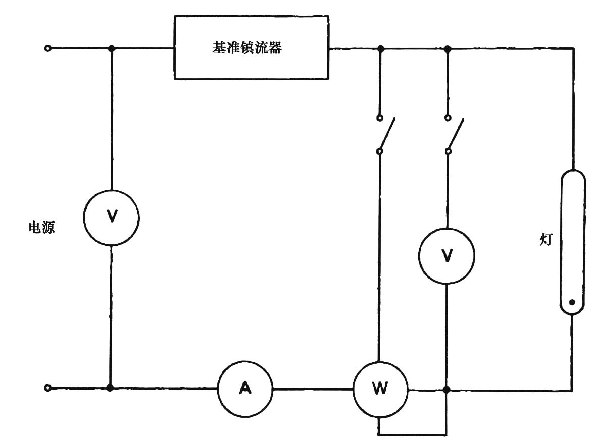
Figure 1 Schematic Diagram of a Circuit for Measuring the Optical and Electrical Parameters of a High-Intensity Gas Discharge Lamp
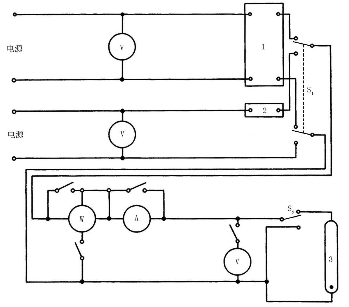
Figure 2: Schematic Diagram of a Test Circuit for Measuring the Lumen Efficiency of Ballasts for High-Intensity Gas Discharge Lamps
In the figure:
1—Test Ballast
2—Reference Ballast
3—Reference Light
Note: 1. When measuring the power of a lamp, short-circuit or turn off any instruments that are not in use.
2. When measuring the lumen maintenance factor, ensure as much as possible that the lamp does not go out when switching safely and quickly from one ballast to another.
3. When measuring metal halide lamps with a power rating of 1000 W or higher, the supply voltage used in the reference ballast’s measurement circuit is higher than that typically used for general measurements. In this case, the measurement power supply can be stepped up via a Voltage Transformer before being connected to the reference ballast’s measurement circuit.
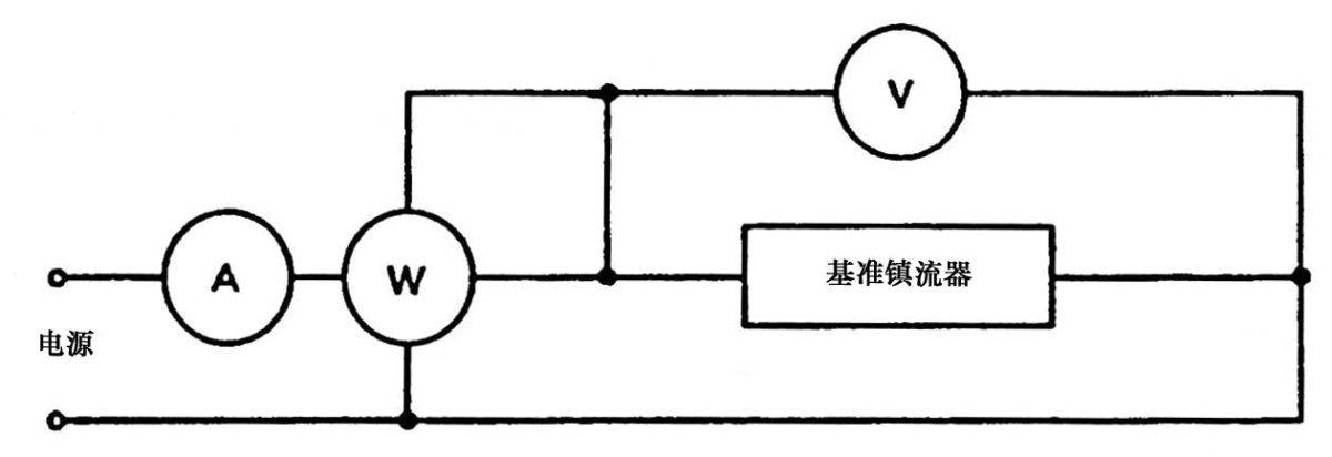
Figure 3: Schematic Diagram of a Calibration Circuit for a Multi-Purpose Reference Ballast for High-Intensity Gas Discharge Lamps
LED Luminaires and LED Power Driver Test Solution
Goniophotometer System: LSG-2000, LSG-1800B, or LSG-1600B
Spectroradiometer & Integrating Sphere Test System: LPCE-2
LED Life Maintains a Test System in Accordance with LM-80: LEDLM-80PL
Waterproof Test for IPX5 and IPX6 Levels: JL-56
Dustproof Testing Machine for IP5X and IP6X Testing: SC-015
LED Power Driver Testers: WT2080 (for the lab) and ATE-2 (for the production line)
Electrical Safety Tester: LS9934
CFL and Electronic Ballast Test Solution
Goniophotometer System: LSG-1800B or LSG-1600B
Integrating Sphere and Spectrophotometer Test System: LPCE-1
Adjustable Reference Ballast: DYJ-50HZ, HCS-105A, and DYJ-HID
Electric Ballast Tester: WT5000 (for the lab) and ATE-1 (for the production line)
Digital Torsion Meter and Multi-Directional Life Tester: CH338 and CH316
Electrical Safety Tester: LS9922I, ZRS-3H, ZY-3
EMC and EMI Test Solutions for CFL and LED Luminaires
EMI Test System: KH3962 or KH3961
Electrostatic Discharge Simulator: ESD61000-2
EFT Immunity Measurement: EFT61000-4
Surge Generator: SG61000-5
Voltage Dips and Interruptions Generator: CSS61000-11
Ring Wave Generator: RWG61000-12

www. Lisungroup.com
Patents Filed
All Rights Reserved by Lisun Group
Subject to Change Without Notice