
 English
 中文简体
中文简体 English
 Русский
 Español
 Português
 Türkçe
 العربية
 Deutsch
 Polski
 Italiano
 Français
 한국어
한국어 ไทย
ไทย Tiếng Việt
 日本語
日本語





























Adjustable Reference Ballast
User's Manual
Applicable LISUN models: DYJ-50HZ、DYJ-60HZ
1. Introduction
The DYJ Adjustable Reference Ballast is suitable for all power-frequency fluorescent lamps currently in use worldwide. When conducting photometric and electrical parameter tests on lamps, it is essential to ensure that the lamps operate under standard conditions to guarantee the accuracy of the data. Under these circumstances, the use of a reference ballast is absolutely necessary; otherwise, different ballasts will yield different test results.
Adjustable reference ballasts can provide different output specifications depending on the type of fluorescent lamp. Equipping each lamp with a separate reference ballast would be extremely costly and would make usage and management inconvenient. Furthermore, this approach would not facilitate the testing of optical and electrical parameters. To address these issues, Lisun Group has developed the DYJ-50HZ/DYJ-60HZ adjustable reference ballasts to meet customers’ diverse needs.
The DYJ Adjustable Reference Ballast strictly complies with the following relevant standards for 50 Hz/60 Hz utility-frequency fluorescent lamps: IEC 60081 (GB/T 10682), IEC 60901 (GB/T 17262), ANSI C78.81 and ANSI C82.3
With the advancement of LED technology, DYJ can also be used to test LED lamps that replace traditional fluorescent lamps.
2. Basic Principles and Key Technical Specifications
The technical specifications for the DYJ Multi-Purpose Reference Ballast are as follows:
Inductance L: 0–1240 Ω
Impedance Linearity Error (within the range of 100 Ω to 1240 Ω) +1%
Resistance R: 0–111 Ω
Operating Current Range 0.12 A to 0.67 A
Power Range of the Test Object 4–85 W
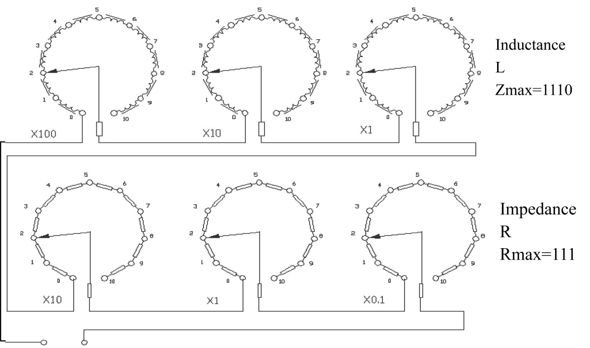
Figure 1: DYJ Front Panel Diagram
Note: The DYJ-50HZ tests all 50-Hz fluorescent lamps, while the DYJ-60HZ can test both 50-Hz and 60-Hz fluorescent lamps.
3. Steps to Follow
Connect the DYJ, the test lamp, the electrical parameter meter, and the AC power source to the circuit as shown in Figure 2 (we recommend using the LISUN LSP-500VAR clean power supply for the AC power source, and either the Yokogawa WT310 or the LISUN LS2008R for the electrical parameter meter):
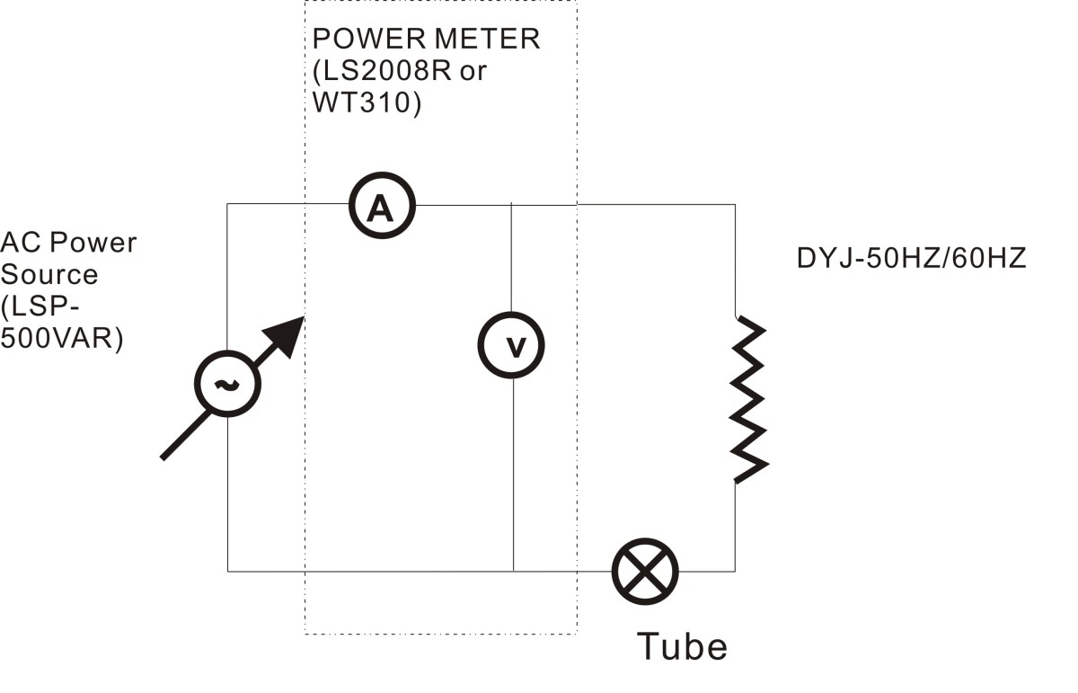
Figure 2: Wiring Diagram for the Test Tube
Locate the “Calibration Certificate” issued by LISUN Laboratory or a third-party laboratory (an additional fee applies for certificates issued by third-party laboratories). Depending on the type of lamp being tested, there are two possible scenarios:
Scenario 1: If the tube type and power of the lamp under test have corresponding Z and R values listed in the “Calibration Certificate” (Figure 3), adjust the corresponding Z and R values on the DYJ panel shown in Figure 2, then output the AC power. At this point, the lamp under test should illuminate, and the corresponding U/I/P/PF values can be measured using the electrical parameter table.
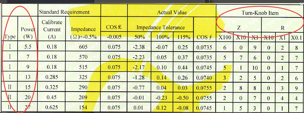
Figure 3: “Calibration Certificate” issued by a third-party laboratory
Scenario 2: If the corresponding Z and R values for the tested lamp’s type and power cannot be found in the Calibration Certificate, you must first determine the Z and R values yourself by following the steps below, and then proceed with the test as described in Scenario 1.
Connect the calibration circuit as shown in Figure 4 (we recommend using the LISUN LSP-500VAR clean power supply for the AC power source and the Yokogawa WT310 electrical parameter meter).
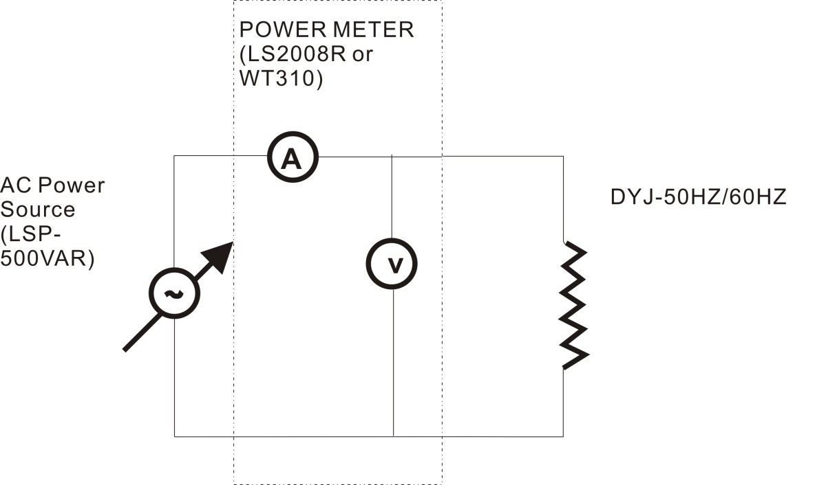
Figure 4: Wiring Diagram for Self-Calibration of Z and R Values
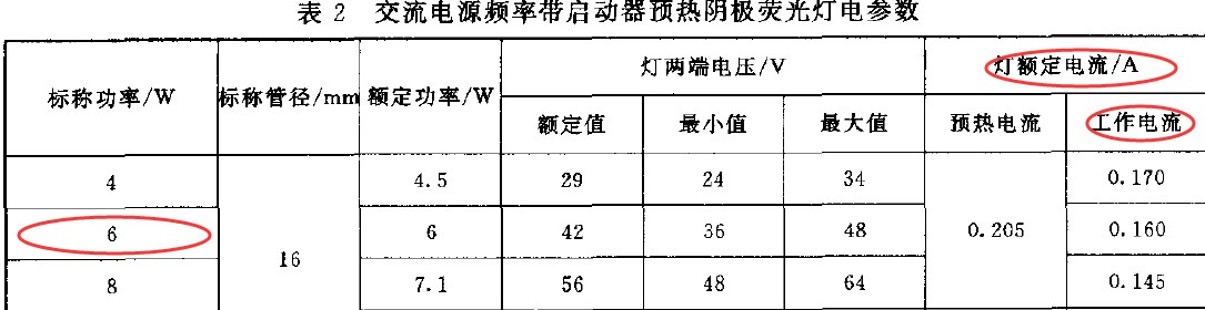
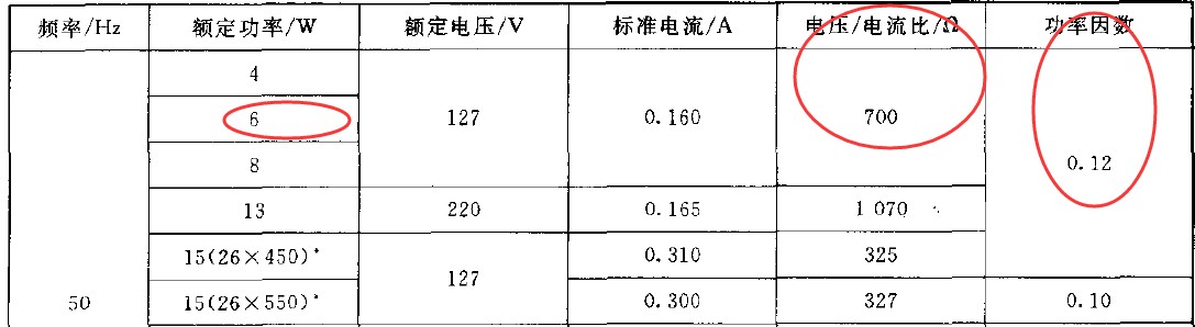
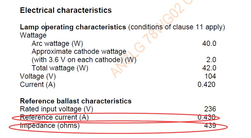
Based on the power rating and tube type of this lamp, refer to the IEC international standard(see Example 1), the GB Chinese standard (see Example 1), or the ANSI American standard (see Example 2), locate the corresponding rated ballast current (or rated lamp current), ballast impedance, frequency, and rated ballast power factor.
Adjust the Z setting on the DYJ panel so that Z equals the ballast impedance; adjust the R setting on the DYJ panel so that R equals 0.
Calculate the input voltage as the rated current multiplied by the resistance, and adjust the voltage and frequency corresponding to the output of the LSP-500VAR AC power supply.
Fine-tune the Z setting on the DYJ panel so that the current reading on the WT310 electrical parameter meter is close to the rated ballast current specified in the standard (increasing Z reduces the current value).
Adjust the R tap on the DYJ panel so that the power factor of the WT310 electrical parameter meter approaches the rated power factor (start by adjusting the x0.1 and x1 settings on the R tap; increasing the R value increases the rated ballast power factor).
Return to the DYJ panel and adjust the X1 setting in the Z position so that the current reading on the WT310 electrical parameter meter is as close as possible to the rated current specified in the standard.
Record the Z and R values on the DYJ panel at this time for the next test of this lamp tube.
How to find the corresponding rated ballast current (or rated lamp current), ballast impedance, frequency, and rated ballast power factor in IEC international standards, GB Chinese standards, or ANSI C78.81 U. S. standards:
Example 1: IEC International Standards (GB Chinese Standards)
As shown in the figure below, take a 50 Hz, 6 W fluorescent tube as an example. According to the standard, the rated current of the tube is I = 0.160 A, the ballast impedance is 700 Ω, the frequency is 50 Hz, and the power factor is 0.12.
Example 2: ANSI C78.81 U. S. Standard
Taking a 40W T10 fluorescent tube as an example, the following information can be found in the standard: the ballast’s rated current is 0.430 A, its impedance is 439 Ω, and the power factor is specified. Complete the calibration according to the above procedure.
4. Important Notes
The two terminals on the bottom of the instrument serve the same function as the two terminals on the panel.
When the DYJ is connected to LISUN’s LPCE-1 system cabinet and the lamp tube is placed inside the Integrating Sphere, the switch on the CASE-19IN cabinet should be set to the “TUBE” position.
The DYJ-60HZ instrument panel is equipped with three terminals. When testing the parameters of 220V, 50Hz FL6W and CFL9W lamps, use terminals 1 and 3; when testing the parameters of other lamps, use terminals 1 and 2.
LED Luminaires and LED Power Driver Test Solution
Goniophotometer System: LSG-2000, LSG-1800B, or LSG-1600B
Spectroradiometer & Integrating Sphere Test System: LPCE-2
LED Life Maintains a Test System in Accordance with LM-80: LEDLM-80PL
Waterproof Test for IPX5 and IPX6 Levels: JL-56
Dustproof Testing Machine for IP5X and IP6X Testing: SC-015
LED Power Driver Testers: WT2080 (for the lab) and ATE-2 (for the production line)
Electrical Safety Tester: LS9934
CFL and Electronic Ballast Test Solution
Goniophotometer System: LSG-1800B or LSG-1600B
Integrating Sphere and Spectrophotometer Test System: LPCE-1
Adjustable Reference Ballast: DYJ-50HZ, HCS-105A, and DYJ-HID
Electric Ballast Tester: WT5000 (for the lab) and ATE-1 (for the production line)
Digital Torsion Meter and Multiway Life Tester: CH338 and CH316
Electrical Safety Tester: LS9922I, ZRS-3H, ZY-3
EMC and EMI Test Solutions for CFL and LED Luminaires
EMI Test System: KH3962 or KH3961
Electrostatic Discharge Simulator: ESD61000-2
EFT Immunity Measurement: EFT61000-4
Surge Generator: SG61000-5
Voltage Dips and Interruptions Generator: CSS61000-11
Ring Wave Generator: RWG61000-12

www. Lisungroup.com
Patents Filed
All Rights Reserved by Lisun Group
Subject to Change Without Notice