
 English
 中文简体
中文简体 English
 Русский
 Español
 Português
 Türkçe
 العربية
 Deutsch
 Polski
 Italiano
 Français
 한국어
한국어 ไทย
ไทย Tiếng Việt
 日本語
日本語





























Reflection/Transmission Test Chamber
User's Manual
Applicable LISUN models: CHTR-100
Safety Regulations
The following safety precautions must be observed at all times when using this instrument; improper use may compromise the instrument’s functionality.
This instrument uses the following symbols:
High-Voltage Warning Symbol: To avoid personal injury or damage to equipment, operators should refer to the instruction manual.


Symbol for a closed switch
Switch Off Symbol
Warning
Do not operate in explosive atmospheres.
Do not use the instrument in areas where flammable or explosive materials are present.
Using any electrical equipment in this environment may result in injury.
Protective Ground Wire
Before connecting the power cord, make sure the protective ground wire is properly connected to prevent damage to the motor. The ground terminal on this instrument is the ground wire terminal on the power outlet.
Power Supply
Before turning on the power, make sure the supply voltage matches the rated voltage.
Do not remove any part of the instrument’s casing.
Some areas carry high voltage; unless you have special permission, you must not remove the instrument’s casing or disassemble any of its components.
1. Overview
Thank you for purchasing the Lishan CHTR-100 Reflectance/Transmittance Test Chamber. Before using this instrument, please first verify that all accessories listed in the “Packing List” on the next page are included. If you find that any accessories are missing or incorrect, please contact our distributor as soon as possible to protect your rights.
This instrument is a precision electronic device. This user manual covers the instrument’s basic principles, main functionality, technical specifications, and operating procedures. To ensure the instrument is used correctly, please read this manual carefully before operating the instrument and keep it in a safe place for quick reference should any issues arise.
The CHTR-100 Reflectance/Transmittance Test Chamber is primarily used to measure various types of mirrors, metals, and plastics
When measuring the (spectral) reflectance of an object’s surface or the (spectral) transmittance of materials such as glass or plastic, photometric and colorimetric data are collected, and the measured light signal is then transmitted via Optical Fibre or photodetectors to a spectrophotometer or a reflectance-transmittance photometer to obtain photometric and colorimetric parameters.
When used in combination with the PM200GL Illuminance/Transmittance Tester, this test chamber is suitable for testing the reflectance of motor vehicle rearview mirrors (or similar products).
2. Principles and Structure
Figure 1: Schematic of the front panel of a reflectance/transmittance test chamber
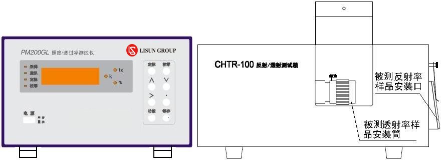
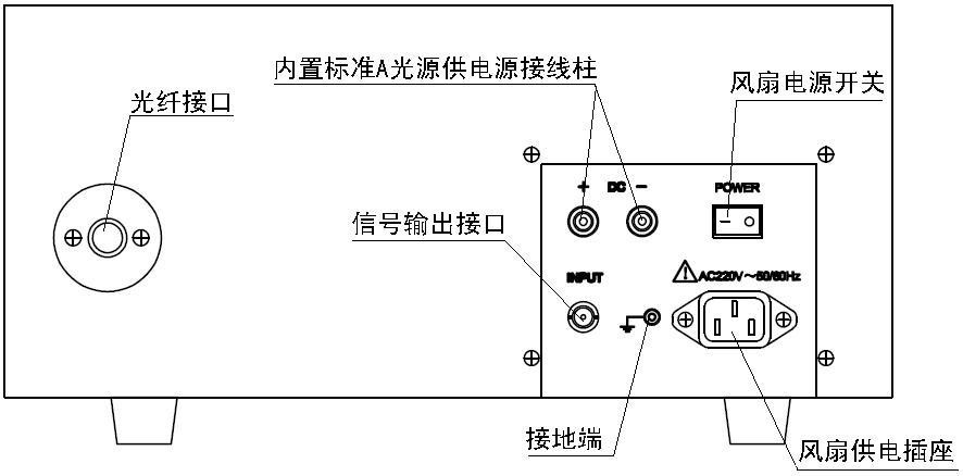
Figure 2: Schematic Diagram of the Rear Panel of a Reflectance/Transmittance Test Chamber
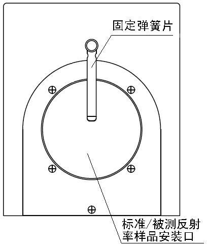
Figure 3: Side View Diagram of a Reflectance/Transmittance Test Chamber
The CHTR-100 Reflectance/Transmittance Test Chamber consists primarily of a Standard Light Source (halogen lamp), an Integrating Sphere, a photometric probe, a parallel light assembly, a cooling fan, mechanical components, and other accessories. For reflectance testing, light from the Standard Light Source is directed through the parallel light assembly directly into the built-in Integrating Sphere. By comparing the light energy data of the test sample with that of a standard sample of known reflectance placed on the side of the Integrating Sphere, the (spectral) reflectance of the test sample is determined. Transmittance testing primarily involves the Standard Light Source passing through the sample under test via the collimator and directly illuminating the built-in Integrating Sphere. By comparing the light energy data before and after the sample under test is placed inside the Integrating Sphere, the (spectral) transmittance of the sample is determined. Therefore, this test chamber primarily uses a combination of a Standard Light Source and an Integrating Sphere to perform comparative measurements and determine reflectance and transmittance parameters.
3. Calibration and Testing of the Test Chamber
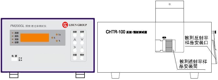
Figure 4: Schematic Diagram of the Calibration of a Reflectance/Transmittance Test Chamber
1. Reflectance Calibration of the Reflectance/Transmittance Test Chamber
Connect the “INPUT” port on the back of the reflectance/transmittance test chamber to the “INPUT” port on the rear panel of the PM200GL Illuminance/Transmittance Tester using the dedicated connection cable. Place the standard reflectance sample plate in the standard/test sample mounting slot and secure it with the retaining spring clip. Connect the standard A light source terminals on the rear of the reflectance/transmittance test chamber to the two output terminals of the WL Series precision digital DC regulated voltage and current power supply.
Turn on the built-in Standard A light source, adjust it to the calibrated current value, and allow it to stabilize for 5 minutes.
Once the above steps are complete, you can calibrate the reflectance using the front panel of the PM200GL Illuminance/Transmittance Tester.
Note: The mounting opening dimensions for standard/test samples are fixed; the actual dimensions of the mounting opening shall prevail. The sample must not be smaller than the opening, but it must also not be too large, otherwise it will not be securely held in place. When not in use, the opening must be sealed with a barium sulfate cover plate to prevent dust from entering the built-in Integrating Sphere.
2. Calibration of Transmittance in a Reflectance/Transmittance Test Chamber
Connect the “INPUT” port on the back of the reflectance/transmittance test chamber to the “INPUT” port on the rear panel of the PM200GL illuminance/transmittance tester using the dedicated connection cable. Open the front cover of the reflectance/transmittance test chamber upward, and check whether there is a sample in the transmittance sample mounting cylinder interface. If so, remove it to ensure the transmittance sample compartment is empty. Move the transmittance sample mounting cylinder until it closes, and secure it with the locking screw. Check whether the reflectance calibration/test sample mounting port has been sealed with a barium sulfate cover plate. Connect the Standard A light source terminals on the back of the reflectance/transmittance test chamber to the two output terminals of the WL series precision digital DC regulated voltage and current power supply.
Turn on the built-in Standard A light source, adjust it to the calibrated current value, and allow it to stabilize for 5 minutes.
Once the above steps are complete, you can calibrate the transmittance using the front panel of the PM200GL Illuminance/Transmittance Tester.
Note: The dimensions of the mounting port for the transmittance test sample are fixed and are based on actual measurements. The sample dimensions must be consistent; otherwise, the sample will not fit into the mounting port. When not in use, the transmittance test sample mounting cylinder must remain closed and secured at all times; otherwise, it will affect the reflectance test.
3. Reflectance Testing
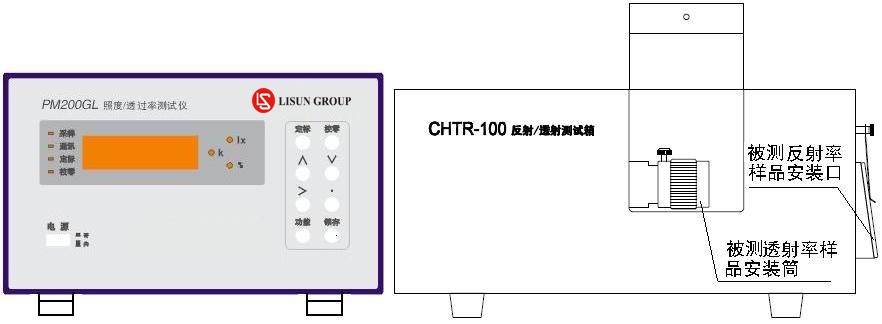
Figure 5: Schematic Diagram of Phosphor Testing
The CHTR-100 Reflectance/Transmittance Test Chamber, when used in conjunction with the PM200GL Illuminance/Transmittance Tester, can form a reflectance testing system for various types of samples, such as mirrors, metals, and plastics. Reflectance calibration must be performed before testing. Once calibration is complete, the sample to be tested should be installed in the mounting port for standard or test samples and securely clamped in place using the spring clips. The built-in standard A light source must remain on at all times, and the calibration current must be verified as correct.
Once the above steps are complete, look at the digital display on the front panel of the PM200GL Direct-Reading Illuminance/Transmittance Tester. The value currently displayed is the reflectance of the sample being tested.
4. Transmission Testing
The CHTR-100 Reflectance/Transmittance Test Chamber, when used in conjunction with the PM200GL Illuminance/Transmittance Tester, can form a transmittance testing system for various glass, plastic, and other material samples. Transmittance calibration must be performed before testing. Once calibration is complete, install the sample to be tested into the interface of the transmittance sample mounting cylinder, move the cylinder until it is fully closed, and secure it with the locking screw. The built-in standard A light source must remain on at all times, and ensure that the calibration current is set correctly.
Once the above steps are complete, look at the digital display on the front panel of the PM200GL Illuminance/Transmittance Tester. The value currently displayed is the transmittance of the sample being tested.
5. Spectral Calibration and Testing of Reflectance/Transmittance
The CHTR-100 Reflectance/Transmittance Test Chamber, when used in conjunction with the LMS-9000 Series Spectral Analyzer, can also form a spectral reflectance/transmittance testing system for various sample types, including mirrors, metals, glass, and plastics. Connect the Optical Fiber from the LMS-9000 Series Spectral Analyzer to the Optical Fiber port on the rear of the CHTR-100 Reflectance/Transmittance Test Chamber and secure it firmly. Begin by performing calibration.
To calibrate reflectance, place a sample plate with a known spectral standard reflectance on the standard/test sample mounting port and secure it with the spring clip. Connect the Standard A light source terminals on the back of the reflectance/transmittance test chamber to the two output terminals of the WL series precision digital DC regulated voltage and current power supply. Turn on the built-in Standard A light source and adjust it to the calibration current value, then allow it to stabilize for 5 minutes. Use the software of the LMS-9000 series spectrometer to perform reflectance spectrum calibration.
When calibrating transmittance, open the front cover of the Reflection/Transmission Test Chamber upward and check whether there is a sample in the transmittance sample holder. If there is, remove it to ensure the transmittance sample holder is empty. Move the transmittance sample holder until it closes, and secure it with the locking screw. Check whether the reflectance calibration/test sample mounting port is sealed with a barium sulfate cover plate. Connect the Standard A light source terminals on the back of the reflectance/transmittance test chamber to the two output terminals of the WL series precision digital DC regulated voltage and current power supply. Turn on the built-in Standard A light source and adjust it to the calibration current value; allow it to stabilize for 5 minutes. Use the LMS-9000 series spectrometer software to perform transmittance spectral calibration.
When performing reflectance testing, after the reflectance spectrum has been calibrated, place the sample plate to be tested in the standard/sample mounting port and secure it with the spring clip. The built-in Standard A light source must remain on at all times, and ensure that the calibration current is correct. Use the software for the LMS-9000 series spectrometer to perform reflectance spectrum measurements.
During transmittance testing, once the transmittance spectrum calibration is complete, install the sample to be tested into the sample holder interface and secure it firmly with screws. The built-in standard A light source must remain on at all times, and ensure that the calibration current is set correctly. Use the software for the LMS-9000 series spectrophotometer to perform the transmittance spectrum test.
5. Important Notes
Keep the inner surface of the Integrating Sphere clean; do not touch the inner surface with your hands or hard objects, and prevent foreign objects from falling into the sphere;
The test chamber should be placed in a dry environment. Do not place it in a damp or corrosive environment, and avoid subjecting it to severe vibration or impact;
The test chamber should be calibrated periodically; during calibration, the reflectance of the standard reflector should be as close as possible to that of the product under test.
4. Packing List
| 1. Host | 1 unit |
| 2. Power cord (3 × 0.75 mm²) | 1 piece |
| 3. Barium sulfate cover plate for the reflectance test port | 1 |
| 4. Shielded signal output cable | 1 piece |
| 5. Product Information CD (includes Certificate of Conformity and Warranty Card) | 1 serving |
| 6. Product Catalog | 1 serving |
LED Luminaires and LED Power Driver Test Solution
Goniophotometer System: LSG-5000, LSG-1800B
Spectroradiometer & Integrating Sphere Test System: LPCE-2, LPCE-3
LED Life Maintains a Test System in Accordance with LM-80: LEDLM-80PL
Waterproof Test for IPX5 and IPX6 Levels: JL-56
Dustproof Testing Machine for IP5X and IP6X Testing: SC-015
LED Power Driver Testers: WT2080 (for the lab) and ATE-2 (for the production line)
Electrical Safety Tester: LS9955
CFL and Electronic Ballast Test Solution
Goniophotometer System: LSG-1800B
Integrating Sphere and Spectrophotometer Test System: LPCE-2
Adjustable Reference Ballast: DYJ-50HZ, HCS-105A, and DYJ-HID
Electric Ballast Tester: WT5000 (for the lab) and ATE-1 (for the production line)
Digital Torsion Meter and Multiway Life Tester: CH338 and CH316
Electrical Safety Testers: LS9922I, ZRS-3H, ZY-3
EMC and EMI Testing Solutions for CFL and LED Luminaires
EMI Test System: EMI-9KB or EMI-9KA
Electrostatic Discharge Simulator: ESD61000-2
EFT Immunity Measurement: EFT61000-4
Surge Generator: SG61000-5
Voltage Dips and Interruptions Generator: CSS61000-11
Ring Wave Generator: RWG61000-12

www. Lisungroup.com
Patents Filed
All Rights Reserved by Lisun Group
Subject to Change Without Notice