
 English
 中文简体
中文简体 English
 Русский
 Español
 Português
 Türkçe
 العربية
 Deutsch
 Polski
 Italiano
 Français
 한국어
한국어 ไทย
ไทย Tiếng Việt
 日本語
日本語





























Ferrite Core Meter
User's Manual
Applicable LISUN models: LS2736、LS2736-05、LS2737-10
To avoid potential hazards, be sure to use this product in accordance with the following instructions:
1) Only personnel authorized by LISUN may perform maintenance operations.
2) Use the manufacturer-specified cable for this product that is approved by the relevant national authorities.
3) Do not plug or unplug the instrument while it is powered on.
4) Be sure to properly ground this product before connecting it to any input or output terminals.
5) Please use this product correctly in accordance with the rated values and labeling instructions provided.
6) Do not operate with the lid open.
7) Avoid exposed wiring.
8) If you suspect that this product is malfunctioning, do not attempt to repair it yourself; contact the manufacturer’s service personnel instead.
9) Maintain adequate ventilation.
10) Do not operate the device in damp or flammable or explosive environments.
11) Keep the product clean and dry.
Instrument Overview
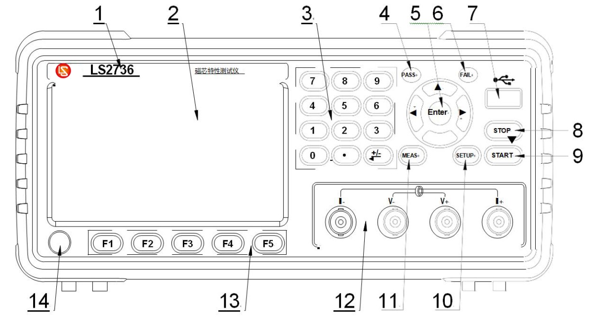
Front Panel Overview:
1
. Logo and Model Number: The instrument’s logo, model number, and measurement range. 2. LCD
Display: A 480×272 dot-matrix LCD display that shows settings, measurement results, measurement conditions, and more. 3
. Numeric Keys: Used to enter numbers, letters, and other relevant information.
4. PASS LED:
Indicates a passing test result. 5. Up, Down, Left, and Right Arrow Keys and [ENTER] Key: When entering values, the [ENTER] key is used to terminate data entry, confirm, and save the data displayed in the bottom row of the LCD. When entering a filename, the [ENTER] key terminates filename entry, confirms the input, saves it, and displays the filename on the bottom line of the LCD. 6
. FAIL LED: Indicates a failed test result.
7. USB HOST port: Used to connect a USB flash drive.
8. STOP key: Keypad lock and unlock key.
9. [Trigger] key and START key: When the instrument’s trigger mode is set to EXT (external trigger) mode, pressing this key triggers the instrument to perform a test.
10. [Set] Key: Press the [Set] key to enter the “Limit List Settings” main menu.
11. [Measure] Key: Press the [Measure] key to enter the “Level Measurement Display” page.
12. Test Terminals: Four-terminal test interface. Used to connect four-terminal test fixtures or test cables to measure the device under test. Current excitation high terminal: Hcur; Voltage sampling high terminal: Hpot; Voltage sampling low terminal: Lpot; Current excitation low terminal: Lcur; 13
. Function Selection Keys: Five function selection keys (F1, F2, F3, F4, F5) are used to select controls and parameters. The left side of each function key corresponds to the function menu on the right side of the LCD display. The function menu on the right varies depending on the display screen.
14. Power Button (POWER): Press this button to turn the power on or off.
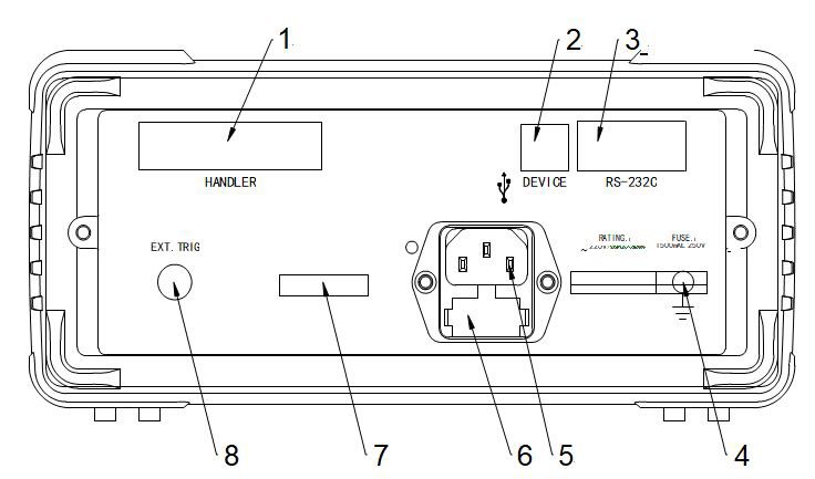
Rear Panel Description:
1. HANDLER Interface The HANDLER interface facilitates the configuration of automated test systems and enables automated testing; it is widely used in automated factory production lines. The instrument uses this interface to output range comparison results and communication signals; it also receives the “Start” signal through this interface. 2
. USBDEVICE Interface ① When the bus mode is set to USBTMC, this port functions as a USBTMC interface. ② When the bus mode is set to USBCDC, this port functions as a USBCDC interface (virtual serial port). ③ When the bus mode is set to USBTMC, this port functions as a USBTMC interface.
3. RS232 Serial Interface This interface can be used to control the instrument.
4. Ground Terminal This terminal is connected to the instrument’s chassis. It can be used for protective or shielding ground connections.
5. Power Socket Used for AC power input. 6
. Fuse Holder Used to install the power fuse to protect the instrument; switching the orientation of the fuse core allows for 110V/220V operation.
7. Instrument Nameplate, Serial Number 8
. EXT. TRIG Input Port When the instrument’s trigger mode is set to external trigger (EXT), this port can be used to trigger the instrument.
※Warning: Before powering on, ensure that your fuse specifications match the supply voltage range.
User Interface Operations
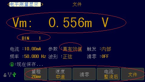
Level Measurement Display Interface:
Display area for the level of the test item.
Range number display area. Range numbers (BIN) 1–14 indicate 14 acceptable ranges; range number L indicates below the limit, and range number H indicates above the limit.
Parameters: Switchable between RMS and average values.
Trigger: Internal, External, Manual. Use the external trigger when connecting to automated equipment; use the internal trigger for manual testing on a test bench.
Waveform: Three modes available: Sine, Half-Wave, and Full-Wave. Special Note: The LS2736 supports only sine wave functionality.
Frequency: 50 Hz or 60 Hz; selectable, with 50 Hz generally recommended.
Zeroing: ON—enables zeroing data recall; OFF—disables zeroing data recall.
F1, F2, F3, F4, F5—a total of 5 soft keys—can be used to switch between or select different functions based on the display in the function area.
Range: 500 mV, 200 mV, 20 mV, 3 mV. For measurement results typically <3 mV, select the 3 mV range; if the measurement result is <20 mV, select the 20 mV range; if <200 mV, select the 200 mV range; if <500 mV, select the 500 mV range.
Speed: Fast, Medium, Slow—selectable.
Current Output Mode: Pre-rectification and post-rectification, referring to full-wave or half-wave rectification. For half-wave: The post-rectification current equals the set value; the pre-rectification current—which excludes the negative half-cycle—does not equal the set value. For full-wave: The current after rectification equals the set value; before rectification, it is the current obtained by inverting the positive half-cycle to the negative half-cycle, which does not equal the set value.
Files: You can access the file interface to perform file operations.
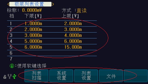
Limit Settings Interface:
Limit List Settings: 2 pages total; Page 1: Set limits for levels 1–7; Page 2: Set limits for levels 8–14. Comparison Method: Direct reading or % can be selected; direct reading is generally used.
Soft Key F1 (List Scan): Enters the list scan interface (customizable feature).
Soft Key F2 (System Settings): Enters the system settings interface.
Soft Key F3 (List Settings): Enters the list settings interface (customizable feature).
Soft Key F4 (Files): Enters the files interface.
File Management Interface:
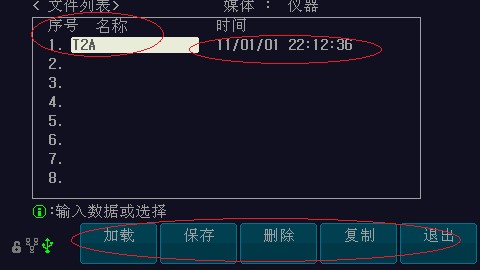
System Settings Interface:
1. Delay: The trigger delay refers to the time between when the instrument triggers a measurement and when the actual measurement is taken.
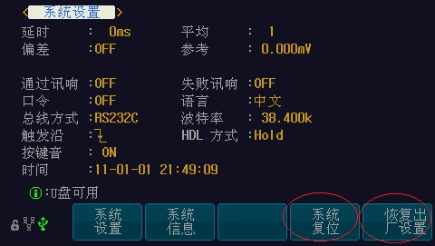
2. Average: The instrument’s “Average” function calculates the average of two or more test results.
3. Offset: Due to various factors affecting the core of the test object, such as temperature, humidity, and electromagnetic interference, it is sometimes necessary to apply an offset to the test results. If offset correction is enabled and a value is set, the displayed result equals the actual measurement ± the offset.
4. Audible Alarms: Different alarm sounds can be set for “pass” and “fail” results.
5. Bus Mode: Selecting different bus modes determines the data transmission method between external devices and the instrument.
6. Language: This feature allows you to switch between Chinese and English.
7. Baud Rate: Used to select the baud rate for the RS-232 interface. When transmitting data to external devices, you must select an appropriate baud rate to enable data exchange with the instrument.
8. Trigger Edge: Select whether to trigger on the rising edge or the falling edge.
9. HDL Mode: Whether to retain or clear the previous trigger signal.
10. Button Sounds: When pressing the buttons on the front panel, you can choose to enable or disable the sound that indicates a successful write operation.
11. Time: You can set the current time.
12. System Reset: This allows you to restart the instrument;
13. Restore Factory Settings: Restores the instrument’s parameters to their factory default settings. Default password: 2786.
Wiring Diagram
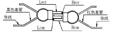
Reset. Note: Before performing a short-circuit reset, you must properly short-circuit the test clamps. As shown in the figure below:
After connecting the test leads according to the wiring method shown in the figure above, press the Reset button to perform the reset, setting the current short-circuit test data to zero. This eliminates measurement errors caused by the test leads.
Testing.
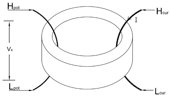
Schematic Diagram of the Test Principle:
※Special Note: As shown in the schematic diagram above, the wiring for the four ports—Hcur, Lcur, Hpot, and Lpot—is fixed. Therefore, when using the instrument to test the device under test (DUT), the instrument’s test leads must be connected as follows: Hcur → Lcur; Hpot → Lpot. Under no circumstances should they be crossed or interconnected.
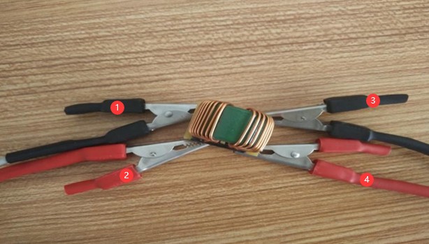
Physical Connection Diagram:
1. Connect to the instrument’s Lpot terminal. 2. Connect to the instrument’s Hpot terminal. 3. Connect to the instrument’s Lcur terminal. 4. Connect to the instrument’s Hcur terminal.
HANDLER Interface User Guide
OK11 1225OK12 1326EXTV1J1R921R922 R923 R924 R925 R926 R927 R920 R928NGLOK13 OK1 OK14 OK2 NGH OK3114215316427/WAIT17OK4VCCR929OK5R930518619OK67COM1 20R931 R939 R932OK78/EOM 21OK89DB25- Bending Hole R933 R934/EXT. TRIG 22 OK910 COM1 23 OK10 1124 R935 R936
The Handler interface uses a 25-pin printed female connector as the output port connector. Its pin assignments are shown in the table below:
| Pins | Corresponding Signal | Description |
| 1 | NGL | Low-level active signal |
| 2 | OK1 | Channel 1: Valid signal, active low |
| 3 | OK2 | Pass signal, Level 2; active low |
| 4 | OK3 | 3-level pass signal, active low |
| 5 | OK4 | 4-channel pass signal, active low |
| 6 | OK5 | 5-level pass signal, active-low |
| 7 | OK6 | Channel 6 enable signal, active low |
| 8 | OK7 | Channel 7 enable signal, active-low |
| 9 | OK8 | Channel 8 enable signal, active low |
| 10 | OK9 | 9-channel pass signal, active-low |
| 11 | OK10 | 10-level valid signal, active-low |
| 12 | OK11 | 11-channel valid signal, active-low |
| 13 | OK12 | 12-channel enable signal, active-low |
| 14 | OK13 | 13-channel enable signal, active low |
| 15 | OK14 | 14-channel enable signal, active low |
| 16 | NGH | Over-range signal, active low |
| 17 | /Wait | Busy signal; a low level indicates that the instrument is in a test or calculation state. |
| 18 | Vcc | Internal power supply output pin (we recommend that customers use an external power supply) |
| 19 | NC | Undefined |
| 20 | COM1 | Reference ground, negative terminal of external power supply (must be connected) |
| 21 | EOM | EOM (End of Message) signal output; active low |
| 22 | TRIG | TRIG (Trigger) Signal Input (Active Low) |
| 23 | COM1 | Reference Location |
| 24 | EXTV1 | External Power Supply Positive Terminal (Must Be Connected) |
| 25 | EXTV1 | External Power Supply Positive Terminal (Must Be Connected) |
Instrument Signal Timing Diagram:
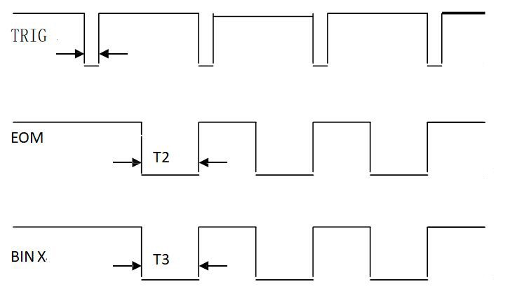
1>.TRIG: Trigger signal; active low; pulse width approximately 4–30 ms. A single low-level trigger signal can only initiate one measurement; even if the signal remains low continuously, only one measurement will be performed.
2>.EOM (End of Measurement) signal, shown as T2 in the figure; active low. When low, it indicates that the sort signal is active but the result has not yet been displayed; when high, it indicates that the device is still being measured.
3>.Bin X: Sorting output signal (T3 in the figure); active low. A low level indicates that the sorting signal is valid, while a high level indicates that the sorting signal is invalid. The sorting output is set to high for every measurement.
Photometric, Colorimetric, and Safety Performance Testing Solutions for LEDs
Goniophotometer System: LSG-6000, LSG-1890B, or LSG-1800ACCD
Spectroradiometer & Integrating Sphere Test System: LPCE-2 or LPCE-3
LED Life Maintains a Test System in Accordance with LM-84: LEDLM-84PL
Photobiological Radiation Safety Test System: EN 62471-C or EN 62471-P
Lamp Start, Run-up Time, and Flicker Test System: LSRF-3 and LSP-500VARC-Pst
LED Power Driver Testers: LS2090, M9822, and LSP-500VARC
IK Level Tester | Spring Hammer Impact Tester: IK07-10, IK01-06
Electrodynamic Vibration Generator System: LVD-100KG-6D
Electrical Safety Testers: LS9955, ZRS-3H, ZY-3, TTC-1
Environmental Chamber Test Solution for LED Luminaires
Waterproof Test for IPX5 and IPX6: JL-56
Dustproof Testing Machine for IP5X and IP6X: SC-015
High- and Low-Temperature and Humidity Chamber: GDJS-015B
Salt Spray Test Machine: YWX/Q-010
UV Lamp Aging Test Chamber: UV-263LS
Xenon Lamp Aging Test Chamber: XD-80LS
Ozone Test Chamber: OTC-150A
Sulfur Dioxide Test Chamber: SQ-010
EMC and EMI Test Solutions for CFL and LED Luminaires
EMI Test System: EMI-9KB or EMI-9KA
Electrostatic Discharge Simulator: ESD61000-2
EFT Immunity Measurement: EFT61000-4
Surge Generator: SG61000-5
Voltage Dips and Interruptions Generator: CSS61000-11
Ring Wave Generator: RWG61000-12

www. Lisungroup.com
Patents Filed
All Rights Reserved by Lisun Group
Subject to Change Without Notice