
 English
 中文简体
中文简体 English
 Русский
 Español
 Português
 Türkçe
 العربية
 Deutsch
 Polski
 Italiano
 Français
 한국어
한국어 ไทย
ไทย Tiếng Việt
 日本語
日本語





























Programmable AC/DC Testing Power Supply System
User's Manual
Applicable LISUN models: LSP-EMC1KVA、LSP-EMC2KVA、LSP-EMC4KVA、LSP-EMC500VA、LSP-EMC6KVA
Please read this manual carefully before using the product. After reading it, keep the manual near the product so you can refer to it when needed. If you move the product to a different location, be sure to take the manual with you.
Although this manual has been carefully reviewed, errors are inevitable. If you find any errors or unclear points, please contact your distributor. Therefore, our company assumes no liability for any errors in the manual’s content or for any direct, indirect, incidental, or consequential damages resulting from the use of this manual.
Copyright Notice: This user manual may not be reprinted, copied, or modified without permission.
Quality Assurance
1. We guarantee that all products we manufacture have undergone rigorous quality control. Products are covered by a twelve-month warranty period from the date of shipment. Any manufacturing defects or malfunctions that occur during this period will be repaired free of charge.
2. For malfunctions caused by users modifying the circuit or features on their own, or for products beyond Products, repair costs will be charged based on the actual circumstances. The Company does not provide free warranty service for malfunctions or damage caused by force majeure.
Safety Instructions
The safety precautions outlined in this section and throughout this manual must be followed at all times during the operation, maintenance, and repair of this product. Failure to follow these safety precautions means the manufacturer disclaims any liability for operations that violate these requirements.
Safety Symbols
1. Definitions of Electrical Symbols, Safety Signs, and Warning Signs
| Symbol | Description | Description | Symbol | Description |
 |
AC | Alternating Current |  |
Prohibited |
 |
DC | Direct Current |  |
Turn on the power |
 |
AC/DC | AC/DC |  |
Disconnect the power supply |
| N | N | Neutral conductor |  |
A switch that turns the power on and off using the same operating element. Typically, such switches have two stable positions. |
 |
PE | Protective conductor |  |
A switch that turns the power on or off using the same operating element. Typically, these switches have two stable positions. |
 |
Grounding | Grounding |  |
High Temperature: Indicates that the temperature here exceeds the range tolerable to the human body. Do not touch this area to avoid injury. |
 |
Safety Precautions: To prevent personal injury or damage to the equipment, operators must follow the instructions in the manual. | Safety Precautions: To prevent personal injury or damage to the equipment, operators must follow the instructions in the manual. |  |
Beware of electric shock |
 |
This symbol indicates a risk. Failure to follow the operating instructions may result in personal injury. Do not operate the equipment until you have fully understood the instructions. | This symbol indicates a risk. Failure to follow the operating instructions may result in personal injury. Do not operate the equipment until you have fully understood the instructions. |  |
This symbol indicates a risk; failure to follow the operating instructions may result in injury or death. This symbol serves as a reminder of procedures, practices, conditions, and other relevant matters. |
2. Safety Briefing
The following general safety precautions must be observed when operating or maintaining this instrument. We assume no liability for any personal injury or equipment damage resulting from the customer’s failure to comply with these precautions or any explicit warnings in this manual.
Please be sure to read this manual carefully before use, and keep it in a safe place.

Do not use the product for purposes other than those described in the manual. This product is intended solely for the uses described in the product manual.
Before connecting the power supply, check that it meets the rated input specifications for this instrument and ensure that the power switch is turned off.
Protective Grounding: Before turning on the power, make sure the protective grounding is connected to prevent electric shock.

The Importance of Protective Grounding: Do not disconnect the internal or external protective grounding wires or break the connection to the protective grounding terminal. Doing so may result in a potential electric shock hazard that could cause injury.

Fuses: Use only fuses with the required current rating, voltage rating, and specific type (standard fuses, time-delay fuses, etc.). Do not use fuses of different specifications or short-circuit fuse holders, as this may result in a risk of electric shock or fire.
Do not remove the instrument’s housing. Operators must not remove the instrument’s housing. Replacement of parts and internal adjustments may only be performed by qualified service personnel.
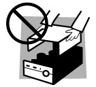
Do not operate the instrument in the presence of explosive or corrosive atmospheres. Do not operate the instrument in the presence of flammable vapors or gases, or in corrosive environments.

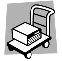
·When moving the product to a new location, turn off the power switch and disconnect all cables. ·The product weighs more than 20 kg; please have at least two people assist when moving it. You can find the product’s weight in the user manual. ·Handle the product with care when moving it to avoid collisions; taller products are prone to tipping over, so handle with caution·Be sure to include the product manual when relocating the product
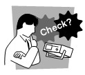
·Check to ensure that the AC input voltage setting matches the fuse rating and that the power cord shows no abnormalities. Before checking, make sure to unplug the power cord or turn off the power switch·If you notice any abnormalities or malfunctions, stop using the product immediately, unplug the power cord, or turn off the power at the circuit breaker panel. Do not use the product until it has been repaired.·Use cables with a high current-carrying capacity for the output or load connections.·Do not disassemble or modify the product. If modifications are necessary, contact the appropriate personnel.
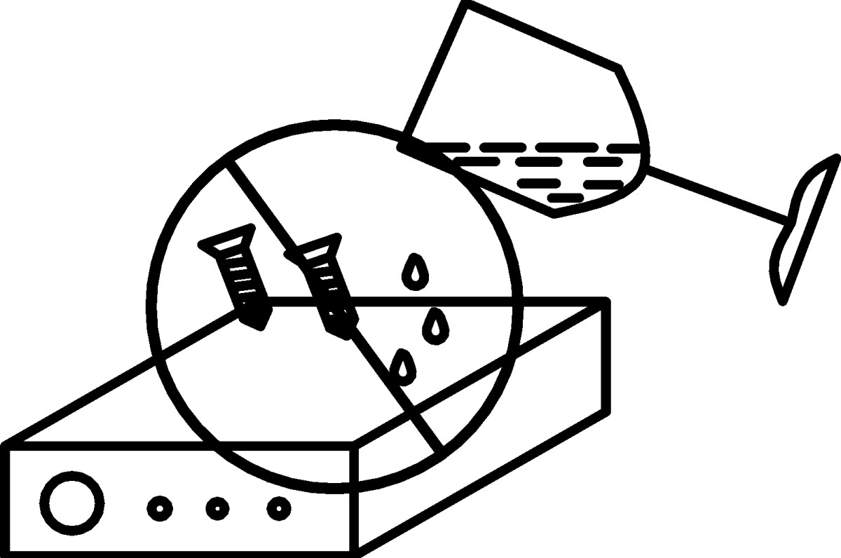
Do not allow water droplets or metal objects to enter the interior of this product.
Product damage resulting from the use of an incorrect power supply is not covered by the product warranty. |
Once the voltage and current have been set and the output is activated, the output terminals carry a hazardous voltage; accidental contact may result in injury or death . . |
HYPERLINK l “_Toc150786888” Chapter 1: Overview 1
HYPERLINK l “_Toc150786889″1.1 Product Overview1
HYPERLINK l “_Toc150786890″1.2 Product Features 1
HYPERLINK l “_Toc150786891″1.3 Feature Overview1
HYPERLINK l “_Toc150786892″1.4 Product Principles 2
HYPERLINK l “_Toc150786893″Chapter 2: Selecting a Product Model 5
HYPERLINK l “_Toc150786894″2.1 Model Naming Conventions5
HYPERLINK l “_Toc150786895″2.2 Relationship Between Output Voltage and Current5
HYPERLINK l “_Toc150786896″2.3 Performance Specifications6
HYPERLINK l “_Toc150786897″Chapter 3: Unpacking and Installation 8
HYPERLINK l “_Toc150786898″3.1 Inspection of Folded Seals 8
HYPERLINK l “_Toc150786899″3.2 Installation Environment 8
HYPERLINK l “_Toc150786900″3.3 Introduction to the Front Panel8
HYPERLINK l “_Toc150786901″3.4 Introduction to the Rear Panel9
HYPERLINK l “_Toc150786902″3.5 External Wiring 10
HYPERLINK l “_Toc150786903″3.5.1 LSP-EMC500VA/1KVA/2KVA External Wiring 10
HYPERLINK l “_Toc150786904″3.5.2 LSP-EMC4KVA/6KVA External Wiring 10
HYPERLINK l “_Toc150786905” Chapter 4: Quick Operations 13
HYPERLINK l “_Toc150786906″4.1 Preparations and Checks Before Use13
HYPERLINK l “_Toc150786907″4.2 Powering On13
HYPERLINK l “_Toc150786908″4.3 Summary Table of Power Supply Functions 14
HYPERLINK l “_Toc150786909″4.4 Shutting Down15
HYPERLINK l “_Toc150786910″Chapter 5: Power Supply Operation 16
HYPERLINK l “_Toc150786911″5.1 Main Menu Screen16
HYPERLINK l “_Toc150786912″5.1.1 Standard Standby/Startup Screen16
HYPERLINK l “_Toc150786913″5.1.2 Normal/Programming Mode Selection Screen17
HYPERLINK l “_Toc150786914″5.1.3 General Settings Interface18
HYPERLINK l “_Toc150786915″5.2 Online Adjustment Function21
HYPERLINK l “_Toc150786916″5.2.1 Changing Numeric Inputs 21
HYPERLINK l “_Toc150786917″5.2.2 Knob Adjustments22
HYPERLINK l “_Toc150786918″5.3 General Settings22
HYPERLINK l “_Toc150786919″5.3.1 Restrictions and Protection Settings22
HYPERLINK l “_Toc150786920″5.3.2 Waveform Settings23
HYPERLINK l “_Toc150786921” 5.3.3 Other Settings 24
HYPERLINK l “_Toc150786922″5.4 System Settings 26
HYPERLINK l “_Toc150786923” 5.4.1 Basic Settings 26
HYPERLINK l “_Toc150786924” 5.4.2 Interface Settings 26
HYPERLINK l “_Toc150786925″5.4.3 Status Settings 28
HYPERLINK l “_Toc150786926″5.4.3 Information Interface 28
HYPERLINK l “_Toc150786927″5.5 Sequence Testing Features29
HYPERLINK l “_Toc150786928” 5.5.1 Sequence Test Function Standby Screen 29
HYPERLINK l “_Toc150786929” 5.5.2 Editing Parameters for Sequence Test Functions 30
HYPERLINK l “_Toc150786930″5.5.3 Operational State of the Sequence Test Function 33
HYPERLINK l “_Toc150786931″5.6 Pulse Output Function33
HYPERLINK l “_Toc150786932″5.6.1 Pulse Output Function Standby Screen 33
HYPERLINK l “_Toc150786933″5.6.2 Editing Pulse Output Function Parameters34
HYPERLINK l “_Toc150786934″5.6.3 Pulse Output Function Operating Mode 35
HYPERLINK l “_Toc150786935″5.6.4 Example of Pulse Parameter Settings 35
HYPERLINK l “_Toc150786936” 5.7 Stepper Test Function 36
HYPERLINK l “_Toc150786937″5.7.1 Stepping Test Function Standby Screen 36
HYPERLINK l “_Toc150786938″5.7.2 Editing Parameters for the Stepping Test Function36
HYPERLINK l “_Toc150786939″5.7.3 Stepping Test Function in Run Mode 37
HYPERLINK l “_Toc150786940″5.8 Harmonic Test Function (LSP-EMC Series Only) 38
HYPERLINK l “_Toc150786941” 5.8.1 Harmonic Test Function Standby Screen 38
HYPERLINK l “_Toc150786942″5.8.2 Editing Parameters for the Harmonic Test Function39
HYPERLINK l “_Toc150786943” 5.8.3 Operational Status of the Harmonic Test Function 40
HYPERLINK l “_Toc150786944″5.9 Interharmonic Test Function (LSP-EMC Series Only)40
HYPERLINK l “_Toc150786945″5.9.1 Interharmonic Test Function Standby Screen 40
HYPERLINK l “_Toc150786946″5.9.2 Editing Interharmonic Function Parameters41
HYPERLINK l “_Toc150786947″5.9.3 Operational States of Interharmonic Functions 42
HYPERLINK l “_Toc150786948″5.10 Harmonic Analysis Function (LSP-EMC Series Only) 43
HYPERLINK l “_Toc150786949″5.10.1 Harmonic Analysis Function Standby Screen 43
HYPERLINK l “_Toc150786950″5.11 Alarm Interface 44
HYPERLINK l “_Toc150786951″Chapter 6: External Interfaces 47
HYPERLINK l “_Toc150786952″6.1 Communication Interfaces47
HYPERLINK l “_Toc150786953″6.1.1 RS232 Interface (Standard) 47
HYPERLINK l “_Toc150786954″6.1.2 RS485 Interface (Optional)47
HYPERLINK l “_Toc150786955″6.1.3 GPIB Interface (Optional)48
HYPERLINK l “_Toc150786956″6.1.4 LAN Port (Optional) 48
HYPERLINK l “_Toc150786957″6.2 Analog Control Interface 48
HYPERLINK l “_Toc150786958″Chapter 7: Maintenance and Quality Assurance 50
HYPERLINK l “_Toc150786959″7.1 Maintenance Guide50
HYPERLINK l “_Toc150786960″7.2 Troubleshooting 50
HYPERLINK l “_Toc150786961” Appendix I: Communication Protocols 51
HYPERLINK l “_Toc150786962″I.1 Hardware Interface Standards 51
HYPERLINK l “_Toc150786963″I.2 LSP 3.0 Communication Protocol 51
HYPERLINK l “_Toc150786964″I.2.1 LSP 3.0 Communication Standard 51
HYPERLINK l “_Toc150786965″I.2.2 List of LSP3.0 Communication Commands 52
HYPERLINK l “_Toc150786966″I.2.3 Detailed Explanation of LSP 3.0 Communication Commands 53
HYPERLINK l “_Toc150786967″I.2.4 LSP 3.0 Response Command 60
HYPERLINK l “_Toc150786968″I.3 SCPI Communication Protocol 61
HYPERLINK l “_Toc150786969″I.3.1 SCPI Communication Standard 61
HYPERLINK l “_Toc150786970″I.3.2 List of SCPI Communication Commands 62
HYPERLINK l “_Toc150786971″I.3.3 Detailed Explanation of SCPI Communication Commands 62
HYPERLINK l “_Toc150786972” Appendix II: Built-in Waveforms 97
1. Overview
Chapter Summary:
Product Overview
Product Features
Feature Overview
How the Product Works
1.1 Product Overview
The LSP-EMC series power supply is an AC test power supply featuring an elegant design, superior performance, powerful functionality, and simple operation. It utilizes advanced pulse-width modulation (PWM) technology to provide low-distortion waveform output. It features three output modes—AC, DC, and AC+DC—and offers measurement capabilities for various parameters, including voltage, current, power, and peak current. The unit also includes multiple protection features, such as overvoltage, overcurrent, overpower, overheat, and fan failure protection, and can communicate with a computer via RS-232C, RS-485, GPIB, or LAN interfaces.
1.2 Product Features
It employs advanced SPWM technology, DSP digital processing technology, and high-power switching power supply technology, resulting in high power density.
Low output distortion, strong load adaptability, and high crest factor.
It features a power-on self-test (POST) function, as well as comprehensive protection and self-diagnostic capabilities, ensuring high reliability.
It features a 9-group, 8-step sequence programming test function, enabling automatic testing of voltage and frequency variations according to a specified slope.
It provides measurement capabilities for various parameters, including voltage, current, power, and peak current, as well as harmonic parameter measurement (the harmonic parameter measurement feature is available only on the ANLSP-EMC series).
It features a pulse output function, enabling voltage dip testing and simulating disturbances found in actual power grids.
It features a step-output function; the step-test mode provides a simple, automatic switching function to change the output voltage, resulting in a step-wise rather than a gradual change.
It features a sequence output function; the output waveform in sequence test mode consists of all possible combinations of the configured sequence numbers. Users can edit the sequence of output voltages as needed.
Features an interharmonic output function. In interharmonic output mode, in addition to providing standard voltage output, the unit can superimpose another voltage component with a variable frequency, which is used in certain anti-interference tests. (Available only on the ANLSP-EMC series.)
Provides an external analog signal input interface to amplify external input signals.
It features an output impedance programming function that allows you to adjust the test power supply’s output impedance as needed.
Features a harmonic synthesis function that enables the output of any periodic voltage waveform. (Available only on the ANLSP-EMC series.)
Features harmonic analysis capabilities to measure the harmonic content of the output voltage and load current. (Available only on the ANLSP-EMC series.)
It features a standard chassis and an LCD display; it is compact and lightweight, and meets the requirements for installation in standard racks.
It has communication capabilities.
1.3 Overview of Features
1. Power-On Self-Test (POST) Function
Each time the system is powered on, it first performs a self-test to check whether the communication system, storage units, and internal modules are functioning properly. If the self-test detects an anomaly, the specific cause of the fault will be displayed.
2. Programmable Test Functions
It features automatic test programming with step-by-step functionality, providing storage space for 9 groups, each with 8 steps, and supports sequential testing between steps within a group. By setting the ramp-up time for the output voltage, it enables controlled ramp-up of the output voltage.
3. Output Functions
It offers three output modes: AC output, DC output, and AC+DC output.
4. Measurement Functions
With powerful measurement capabilities, it provides measurements such as RMS voltage and current, DC voltage and current, peak current, inrush current, current crest factor, active power, reactive power, apparent power, and power factor. The ANLSP-EMC series offers harmonic measurement capabilities.
5. Custom Waveform Function
Customizable waveform outputs include sine waves, square-like waves, clamped sine waves, and system-built-in waves;
6. Start-Stop Angle Control
By setting the start angle and stop angle, you can control the start and stop angles of the output voltage waveform.
7. Output Gradient Control
It allows the output voltage to change at a set rate until it reaches the set value.
8. Pulse Output Function
Voltage dip and surge suppression testing is achieved by configuring the pulse voltage output.
9. Step Output Function
The step test mode provides a simple, automatic switching function to change the output voltage in discrete steps rather than gradually.
10. Sequence Output Function
The output waveforms in sequence test mode represent all possible combinations of sequence numbers. Users can edit the sequence of output voltages as needed.
11. Interharmonic Output Function (Available only on the ANLSP-EMC series)
In the interharmonic output mode, in addition to providing standard voltage output, another frequency-variable voltage component can be superimposed for use in certain anti-interference tests.
12. Externally Specified Control
By inputting an external analog signal to control the power supply’s output voltage, the system amplifies the input signal.
13. Output Impedance Control
By adjusting the output impedance of the test power supply, the test requirements of a specific load can be met.
14. Harmonic Output Function (Available only on the ANLSP-EMC series)
Supports harmonic synthesis output up to the 40th order.
15. Communication Features
It communicates with the host computer via a communication interface, making it easy to operate.
16. Protection Features
Equipped with comprehensive protection and self-diagnostic functions, it provides protection against overcurrent, overpower, overvoltage, internal power module failures, output short circuits, input undervoltage, fan failures, and overheating, among others, and displays specific fault diagnostic information to facilitate product maintenance.
1.4 Product Principles
Figure 1.1 shows the overall system architecture of the test power supply, which consists of a total of nine modules. First, the power supply’s main circuit passes through the PFC module, the DC-DC conversion module, and the DC-AC conversion module on the power supply board, ultimately generating an AC output voltage. The PFC module converts the AC input into a DC voltage, which serves as the input for the next-stage DC-DC conversion module; The DC-DC conversion module then generates two sets of isolated DC outputs for use by the DC-AC conversion module; finally, the AC output voltage is produced by the DC-AC conversion module.
The main control and measurement module is responsible for controlling the DC-AC conversion module, adjusting the output voltage and frequency, and simultaneously measuring the output voltage and current values; the power supply is remotely controlled via the TTL module and the RS-232C/RS-485/GPIB/LAN modules, and human-machine interaction is facilitated through pushbuttons and a touchscreen display module.
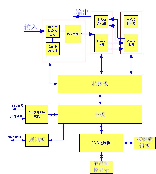
Figure 1.1 System Architecture of the LSP-EMC500VA/1KVA/2KVA System
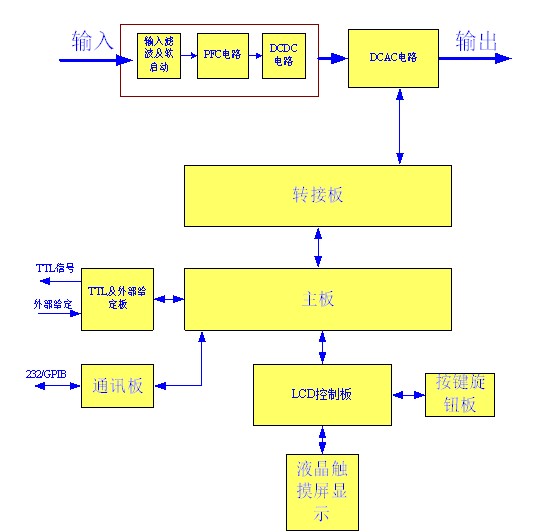
Figure 1.2 System Architecture of the LSP-EMC4KVA/6KVA System
2. Select a product model
Chapter Summary:
Model Naming Convention
Correlation Between Output Voltage and Current
Performance Specifications
2.1 Model Naming Convention
LSP-EMC500VA
LSP-EMC1KVA
LSP-EMC2KVA
LSP-EMC4KVA
LSP-EMC6KVA
2.2 Relationship Between Output Voltage and Current
The relationship between output voltage and maximum output current is shown in Figures 2.2 and 2.3. Curve a represents the relationship between output voltage and maximum output current in the low range, while curve b represents the relationship between output voltage and maximum output current in the high range.
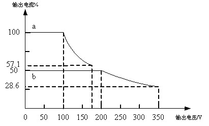
Figure 2.2 Relationship Between Power Supply Output Voltage and Current (LSP-EMC Series)
2.3 Performance Specifications
| Model | Model | Model | LSP-EMC500VA | LSP-EMC1KVA | LSP-EMC2KVA | LSP-EMC4KVA | LSP-EMC6KVA |
| Input | Input | Input | Input | Input | Input | Input | |
| Number of Phases | Number of Phases | Number of phases | Single-phase | Single-phase | Three-phase, five-wire | Three-phase, five-wire | |
| Voltage Range | Voltage Range | Voltage Range | 90 V–250 V AC | 90 V–250 V AC | 340 V–420 V AC | 340 V–420 V AC | |
| Frequency Range | Frequency Range | Frequency Range | 47–63 Hz | 47–63 Hz | 47–63 Hz | 47–63 Hz | |
| Maximum Current | Maximum Current | Maximum Current | LSP-EMC500VA | LSP-EMC1KVA | LSP-EMC2KVA | LSP-EMC4KVA | LSP-EMC6KVA |
| Maximum Current | Maximum Current | Maximum Current | 8A | 16A | 28A | 18A | 25A |
| Minimum Power Factor | Minimum Power Factor | Minimum Power Factor | 0.97 | 0.97 | 0.98 | 0.98 | |
| AC Output | AC Output | AC Output | AC Output | AC Output | AC Output | AC Output | |
| Maximum Power | Maximum Power | Maximum Power | LSP-EMC500VA | LSP-EMC1KVA | LSP-EMC2KVA | LSP-EMC4KVA | LSP-EMC6KVA |
| Maximum Power | Maximum Power | Maximum Power | 500 VA | 1000 VA | 2000 VA | 4000 VA | 6000 VA |
| Voltage | Scope | 0–350 V | 0–350 V | 0–350 V | 0–350 V | 0–350 V | |
| Voltage | Accuracy | 0.2% + 0.2% F. S. | 0.2% + 0.2% F. S. | 0.2% + 0.2% F. S. | 0.2% + 0.2% F. S. | 0.2% + 0.2% F. S. | |
| Voltage | Resolution | 0.01 V | 0.01 V | 0.01 V | 0.01 V | 0.01 V | |
| Voltage | Distortion*1 | 0.3% at 50/60 Hz, 1% at 15–1 kHz | 0.3% at 50/60 Hz, 1% at 15–1 kHz | 0.3% at 50/60 Hz, 1% at 15–1 kHz | 0.3% at 50/60 Hz, 1% at 15–1 kHz | 0.3% at 50/60 Hz, 1% at 15–1 kHz | |
| Start/Stop Angle | Scope | 0–359.9° | 0–359.9° | 0–359.9° | 0–359.9° | 0–359.9° | |
| Start/Stop Angle | Resolution | 0.1° | 0.1° | 0.1° | 0.1° | 0.1° | |
| Start/Stop Angle | Accuracy | 1° (45–65 Hz) | 1° (45–65 Hz) | 1° (45–65 Hz) | 1° (45–65 Hz) | 1° (45–65 Hz) | |
| Source Effect | Source Effect | Source Effect | 0.10% | 0.10% | 0.10% | 0.10% | |
| Load Effect*2 | Load Effect*2 | Load Effect*2 | 0.20% | 0.20% | 0.20% | 0.20% | |
| Peak Factor | Peak Factor | Peak Factor | ≥4 | ≥4 | ≥4 | ≥4 | |
| Temperature Coefficient | Temperature Coefficient | Temperature Coefficient | Starting at 25°C, 0.02%/°C | Starting at 25°C, 0.02%/°C | Starting at 25°C, 0.02%/°C | Starting at 25°C, 0.02%/°C | |
| LSP-EMC500VA | LSP-EMC1KVA | LSP-EMC2KVA | LSP-EMC4KVA | LSP-EMC6KVA | |||
| Maximum Current (RMS) | 0–175 V | 5A | 10A | 20A | 40A | 60A | |
| Maximum Current (RMS) | 0–350 V | 2.5A | 5A | 10A | 20A | 30A | |
| Maximum Current (Peak) | 0–175 V | 20A | 40A | 80A | 160A | 240A | |
| Maximum Current (Peak) | 0–350 V | 10A | 20A | 40A | 80A | 120A | |
| Frequency | Scope | 15–1000 Hz | 15–1000 Hz | 15–1000 Hz | 15–1000 Hz | 15–1000 Hz | |
| Frequency | Accuracy | 0.15% | 0.15% | 0.15% | 0.15% | 0.15% | |
| Frequency | Resolution | 0.001 Hz | 0.001 Hz | 0.001 Hz | 0.001 Hz | 0.001 Hz | |
| DC Output | DC Output | DC Output | DC Output | DC Output | DC Output | DC Output | |
| Voltage Range | Voltage Range | Voltage Range | 247.5 V / 495.0 V | 247.5 V/495.0 V | 247.5 V / 495.0 V | 247.5 V / 495.0 V | |
| Maximum Power | Maximum Power | Maximum Power | LSP-EMC500VA | LSP-EMC1KVA | LSP-EMC2KVA | LSP-EMC4KVA | LSP-EMC6KVA |
| Maximum Power | Maximum Power | Maximum Power | 250W | 500W | 1000 W | 2000 W | 3000 W |
| Maximum Current | -247.5 – 247.5 V | 2.5A | 5A | 10A | 20A | 30A | |
| Maximum Current | -495.0–495.0 V | 1.25 A | 2.5A | 5A | 10A | 15A | |
| Measurement Parameters | Measurement Parameters | Measurement Parameters | Measurement Parameters | Measurement Parameters | Measurement Parameters | Measurement Parameters | |
| Voltage Range | Voltage Range | Voltage Range | 175 V / 350 V | 175 V / 350 V | 175 V / 350 V | 175 V / 350 V | |
| Voltage Accuracy | Voltage Accuracy | Voltage Accuracy | 0.2% + 0.2% F. S. | 0.2% + 0.2% F. S. | 0.2% + 0.2% F. S. | 0.2% + 0.2% F. S. | |
| Voltage Resolution | Voltage Resolution | Voltage Resolution | 0.01 V | 0.01 V | 0.01 V | 0.01 V | |
| Current Range (Peak) | Current Range (Peak) | Current Range (Peak) | LSP-EMC500VA | LSP-EMC1KVA | LSP-EMC2KVA | LSP-EMC4KVA | LSP-EMC6KVA |
| Current Range (Peak) | Current Range (Peak) | Current Range (Peak) | 20A | 40A | 80A | 160A | 240A |
| Current Accuracy (RMS) | Current Accuracy (RMS) | Current Accuracy (RMS) | 0.4% + 0.6% F. S. | 0.4% + 0.6% F. S. | 0.4% + 0.6% F. S. | 0.4% + 0.6% F. S. | |
| Current Accuracy (Peak) | Current Accuracy (Peak) | Current Accuracy (Peak) | 0.4% + 0.6% F. S. | 0.4% + 0.6% F. S. | 0.4% + 0.6% F. S. | 0.4% + 0.6% F. S. | |
| Current Resolution | Current Resolution | Current Resolution | 0.01 A | 0.01 A | 0.01 A | 0.01 A | |
| Power Accuracy | Power Accuracy | Power Accuracy | 0.4% + 0.6% F. S. | 0.4% + 0.6% F. S. | 0.4% + 0.6% F. S. | 0.4% + 0.6% F. S. | |
| Power Resolution | Power Resolution | Power Resolution | 0.1 W | 0.1 W | 0.1 W | 0.1 W | |
| Other | Other | Other | Other | Other | Other | Other | |
| LSP-EMC500VA | LSP-EMC1KVA | LSP-EMC2KVA | LSP-EMC4KVA | LSP-EMC6KVA | |||
| Efficiency | Efficiency | Efficiency | 68% | 77% | 80% | 83% | 83% |
| Weight | Weight | Weight | 21 kg | 21 kg | 40 kg | 40 kg | |
| Interface | Interface | Interface | Standard: RS-232C and TTL control interfaces; Optional*3: RS-485, GPIB, and LAN communication interfaces | Standard: RS-232C and TTL control interfaces; Optional*3: RS-485, GPIB, and LAN communication interfaces | Standard: RS-232C and TTL control interfaces; Optional*3: RS-485, GPIB, and LAN communication interfaces | Standard: RS-232C and TTL control interfaces; Optional*3: RS-485, GPIB, and LAN communication interfaces | |
| Dimensions (Width × Height × Depth) | Dimensions (Width × Height × Depth) | Dimensions (Width × Height × Depth) | 433 mm × 132 mm × 630 mm (3U standard chassis) | 433 mm × 132 mm × 630 mm (3U standard chassis) | 433 × 221 × 640 (5U standard chassis) | 433 × 221 × 640 (5U standard chassis) | |
| Protected Species | Protected Species | Protected Species | Protection against overvoltage, overcurrent, overpower, overheating, fan failure, etc. | Protection against overvoltage, overcurrent, overpower, overheating, fan failure, etc. | Protection against overvoltage, overcurrent, overpower, overheating, fan failure, etc. | Protection against overvoltage, overcurrent, overpower, overheating, fan failure, etc. | |
| Operating Environment | Operating Environment | Operating Environment | 0–40°C / 30–90% RH | 0–40°C/30–90% RH | 0–40°C/30–90% RH | 0–40°C/30–90% RH |
Note: The performance parameters listed above were measured at 25°C under a resistive load.
*1: Distortion is measured at the maximum current with an output voltage of 100 VAC (low range) or 200 VAC (high range).
*2: The load effect was measured with a sine wave output connected to the SENSE terminal.
*3: If any of the RS485, GPIB, or LAN options are selected, the RS232C interface is not available.
3. Unpacking and Installation
Chapter Summary:
Unboxing and Inspection
Installation Environment
Introduction to the Front Panel
Introduction to the Rear Panel
External Wiring
3.1 Inspection of Folded Seals
After unpacking, first check the product nameplate to verify that the model matches your order; then, refer to the “Packing List” in the user manual to ensure that all accessories and documents are included; remove the power supply and inspect it for any shipping damage, missing fasteners, or other abnormalities.
Please read the user manual carefully before using the product. Confirm the input power supply requirements, then connect the power supply, turn on the switch, activate the power output, and check that all functions are working properly.
If you notice any abnormalities with the items listed above, please contact our customer service center immediately and retain the packaging materials for future shipping.
3.2 Installation Environment
During installation, ensure the power supply is well-ventilated and can dissipate heat effectively. The distance between the power supply’s air intake (and exhaust) vents and walls or obstructions should be at least 30 cm. Avoid placing it in areas exposed to direct sunlight or high humidity and heat, and never allow it to get wet.
3.3 Introduction to the Front Panel
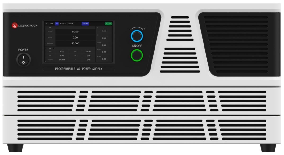
A schematic diagram of the front panel of the LSP-EMC series AC test power supply is shown in Figure 3.1.
LSP-EMC500VA 0–350 V 0–5 A 0.5 kVA

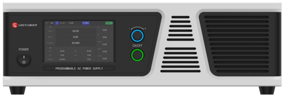
LSP-EMC500VA/1KVA/2KVA Series Front Panel
2LSP-EMC500VA 0–350 V 0–60 A 3 kVA 134

LSP-EMC4KVA/6KVA Series Front Panel
Figure 3.1 Front Panel and Button Control Area
Main Power Switch: Turns the power on or off.
LCD display: A touchscreen used to set parameters and display test results.
3. Power Button: Used to turn the device on or off in normal mode.
4. Knob Button: Press once to activate the knob function; the blue light will illuminate when activated. Use the touchscreen to select the parameter you wish to adjust; an underline may appear below it. At this point, press the knob again to select the digit you want to adjust, then rotate the knob to change the parameter. Touch the parameter to be adjusted again to remove the underline; pressing the knob turns off the blue light and deactivates the knob function.
3.4 Introduction to the Rear Panel
Schematic diagrams of the rear panels of the LSP-EMC series AC test power supplies are shown in Figures 3.2 and 3.3.
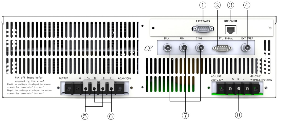
Figure 3.2 Schematic Diagram of the Rear Panel of the LSP-EMC500VA/1KVA/2KVA
1. RS-232/485: 9-pin serial port for remote communication and control with a PC. RS-232 communication is standard; RS-485 communication is optional.
2. TTL Signals: 9-pin connector used to transmit control signals: ACON, FAULT, and REMOTE-CONTROL. See Chapter 6 for details.
3. GPIB/LAN: The GPIB bus interface or LAN port are both optional.
4. EXT VREF: BNC input terminal for an externally supplied analog signal.
5. Measurement terminals SL and SN: These are used for four-wire testing when compensating for lead voltage. SL and SN correspond to the L and N input terminals of the load, respectively; be careful not to reverse their connections. When lead voltage can be neglected, use shorting clips to short SL to L and SN to N, respectively.
6. Output terminals L and N: Power supply output terminals that connect directly to the load. When the output voltage contains a DC component, terminal “L” is the “+” terminal, and terminal “N” is the “−” terminal.
7. SCLK, PWM, SYNC: Invalid signals.
8. Power Input Terminal: Used to connect an external AC voltage source.
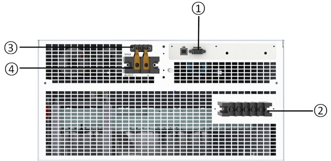
Figure 3.4 Schematic Diagram of the Rear Panel of the LSP-EMC4KVA/6KVA
1. RS-232/485: 9-pin serial port for remote communication and control with a PC. RS-232 communication is standard; RS-485, GPIB, and LAN communication are optional.
2. Power Input: Used to connect an external AC voltage source.
3. Output terminals L and N: Power supply output terminals that connect directly to the load. When the output voltage contains a DC component, terminal “L” is the “+” terminal, and terminal “N” is the “−” terminal.
4. Measurement terminals SL and SN: These are used for four-wire testing when lead voltage compensation is required. SL and SN correspond to the L and N input terminals of the load; be sure not to reverse their connections. When lead voltage can be neglected, use shorting clips to short SL to L and SN to N, respectively.
3.5 External Wiring
3.5.1 LSP-EMC500VA/1KVA/2KVA External Wiring
| Input Connection | 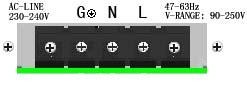 |
“L,” “N,” and “G” are connected to the live wire, neutral wire, and ground wire of the power cord, respectively. Do not use three separate wires to connect to the power source. |
| Output Connection | 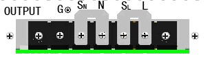 |
The output connectors are located on the rear of the AC test power supply; “L” and “SL,” as well as “N” and “SN,” are connected as output terminals using shorting bridges, respectively, and the load is connected to the “N” and “L” output terminals. For a four-wire test, remove the SL and SN shorting bridges and connect the two ends to the load’s L and N input terminals, respectively. |
3.5.2 LSP-EMC4KVA/6KVA External Wiring
(1) Input Wiring
1. Input Voltage
Voltage: 340–420 VLL, three-phase, five-wire Y configuration;
Frequency: 47–63 Hz
Maximum current: 14 A (single-phase);
Note: If the input voltage of the AC test power supply exceeds the specified range, it may be damaged.
It is recommended to use circuit breakers for the input wiring: The minimum rating of the circuit breaker selected for each circuit should be 380V/14A;
2. Input Wiring
The rated current of the input power supply selected by the user must be greater than or equal to the maximum input current of the AC test power supply, and the rated temperature of the cord must be at least 85°C.
(2) Output Wiring
Pay attention to the L and N markings on the output terminals to ensure correct connections. To ensure safe and accurate testing, tighten the screws securely when connecting the load. Additionally, use wiring with a sufficiently large cross-sectional area to connect the load to the power supply, and install a wiring guard. The selected load wiring should have a sufficiently large cross-sectional area to prevent the wires from overheating when the output current is high.
(3) Remote Measurement Wiring
An AC test power supply can monitor the voltage at the load end via remote measurement, rather than monitoring the voltage at its output terminals. This allows it to automatically compensate for voltage drops in the connecting cables, ensuring that the voltage delivered to the load matches the set voltage.
Remove the shorting tabs from the telemetry terminals SN and SL, and connect them to the load end using telemetry leads. The telemetry leads are part of the AC test power supply voltage measurement circuit; it is best to use low-resistance leads, as the current flowing through them is only a few milliamps. It is best to use multi-strand twisted wire for the telemetry leads to reduce external voltage interference, and to route them as close as possible to the connected load. Ensure that the telemetry leads are securely connected; if they are not connected or become open during operation, the power supply will not be able to output power.
Power cords selected or replaced by users must meet at least the following requirements:
(1) Rated voltage: 500 V
(2) Wire gauge: ≥2 mm²
(3) Internal insulation material: polyvinyl chloride
(4) External insulation material: polyvinyl chloride
(5) Rated temperature: >70°C
In addition, any power output cable selected or replaced by the user must meet at least the following requirements:
(1) Rated voltage: 500 V
(2) Wire cross-sectional area: ≥10 mm²
(3) Internal insulation material: polyvinyl chloride
(4) External insulation material: polyvinyl chloride
(5) Rated temperature: >70°C
In addition, one of the following measures should be taken to prevent the power cord from becoming frayed or sharply bent at the cable entry point:
(1) Use cable entry ports and bushings with smooth, rounded openings;
(2) Use a flexible cable sheath made of insulating material that can be securely fastened; the portion of the sheath extending beyond the entry point must be at least five times the outer diameter of the wire with the largest cross-sectional area that can be installed. For flat flexible cables, the outer diameter shall be determined based on the largest dimension of the cable’s outer cross-section.
Power cord fasteners shall be designed to relieve the conductors of the power cord from stress, including torsional stress, at the point where the cord is connected to the equipment, and shall prevent wear on the insulation of the conductors. If the power cord slips out of its fastener, its protective grounding conductor, if any, shall be the last to be subjected to stress.
If this test equipment is not intended to be moved easily after installation—that is, if it is to be used as a permanent connection—it is recommended that users employ a switch or circuit breaker as the disconnecting device. This device must meet the following requirements:
(1) Switches or circuit breakers shall be included in the building’s facilities;
(2) Switches should be located near the equipment and within easy reach of the operator;
(3) Switches or circuit breakers shall be marked as disconnecting devices for that equipment;
To ensure safe and accurate testing, the screws must be tightened when connecting the load, and the wire gauge connecting the load to the power source must be sufficiently large. Additionally, install a wiring guard, as shown in Figures 3.7, 3.8, and 3.9.
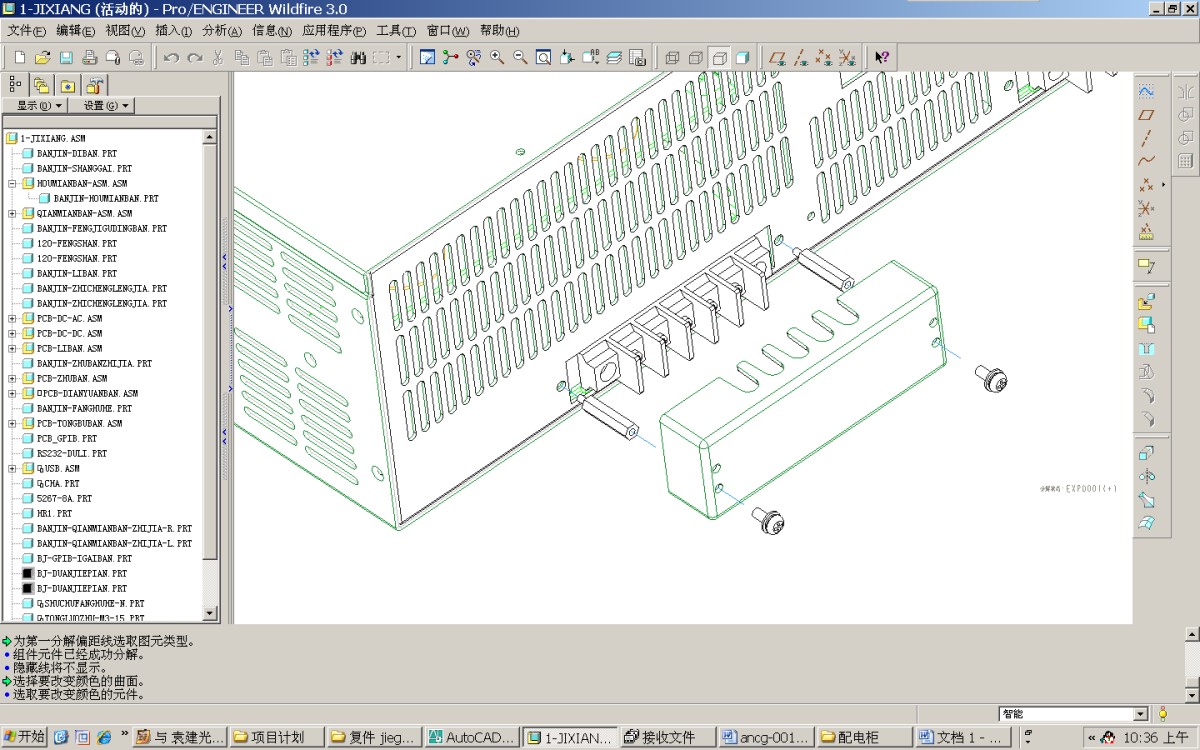
Figure 3.5 Installation Diagram for the Rear Panel Protective Cover of the LSP-EMC500VA/1KVA/2KVA
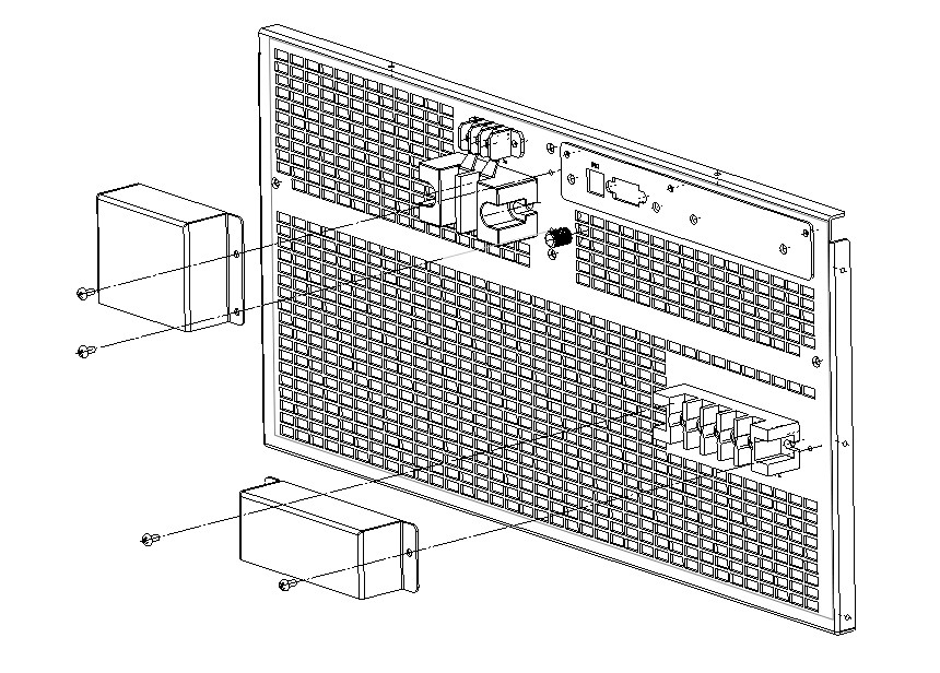
Figure 3.6 Installation Diagram for the Rear Panel Guard of the LSP-EMC4KVA/6KVA
The power supply must be properly grounded (marked “PE” or at the terminal block); otherwise, the chassis may become electrically charged, which could cause injury to personnel or damage to the equipment under test. To ensure personal safety, do not touch input or output terminals or other areas where electric shock may occur until the input power supply has been disconnected. When connecting the output terminals, select power cords and other accessories that are suitable for the output current and power rating. If the plastic cover of the terminal block is damaged, contact the manufacturer immediately to arrange for a replacement to prevent the risk of electric shock. |
When the output voltage contains a DC component, the “L” output terminal is the “+” terminal, and the “N” output terminal is the “−” terminal. |
4. Quick Operations
Chapter Summary:
Preparation and Inspection Before Use
Power On
Overview of Operations
Shut Down
4.1 Preparations and Checks Before Use
(1) Please read the safety and warning labels affixed to the instrument carefully before use.
(2) Ensure that no debris is blocking the ventilation openings on the power supply.
(3) Ensure that the power cord and input/output cables are connected correctly
Be sure to connect the input and output wires correctly! |
Before turning on the power, all protective grounding terminals, extension cords, and devices connected to the instrument must be connected to a protective ground. Any interruption in the protective grounding connection will result in a potential risk of electric shock, which may cause personal injury. |
4.2 Powering On
41 After correctly connecting the input and output cables, turn on the POWER switch. The power supply panel will display the startup screen. During startup, the power supply performs an internal self-test and undergoes a soft-start charging process. If the self-test fails, the display will switch to the corresponding alarm screen. If the self-test is successful, after approximately 10 seconds, the self-test and soft-start charging process will complete, and the display will switch to the corresponding standby screen, as shown in Figure 4.2.1.
523
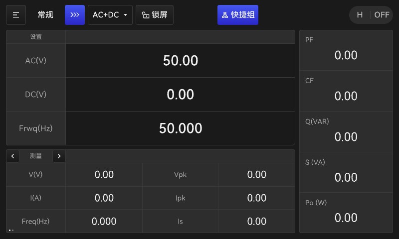
Figure 4.2.1 Standby Screen
As shown in Figure 4.2.1, the main menu screen is divided into five areas, which are:
1: Title Area: Used to indicate the status of the currently displayed interface; you can also modify the title bar parameters;
2: Parameter Settings Area: Used to display key information such as settings and measurement operations;
3: Measurement display area: Used to display measurement results;
High/Low Display Area: Used to display the power supply’s operating status; options include H (High), L (Low), and A (Auto).
4: ON/OFF display area: Used to indicate the power status; when the power is in standby mode, it displays “OFF” in gray; when powered on, it displays “ON” with a green light;
5: Power Factor, Crest Factor, and Power Measurement Area: Used to display the calculated results for power factor and crest factor, as well as the measured values for reactive, apparent, and active power.
4.3 Summary Table of Power Supply Functions
Table 4.3.1 Summary of Power Supply Functions
| Power Status | Actions You Can Take |
| Normal Mode – Standby State | Within 8 to 10 seconds of turning on the device, it will enter the standby screen that was displayed when it was last shut down. |
| Normal Mode – Standby State | >>> key to enter parameter editing in normal mode (Page 2) |
| Normal Mode – Standby State | ≡ key: Enter Normal Mode/Programming Mode/General Settings/System Settings (Page 2) |
| Normal Mode – Standby State | AC+DC button: Select output mode—AC/DC, AC, or DC |
| Normal Mode – Standby State | Lock Screen Button: Enters Lock Screen Mode (Page 2) |
| Normal Mode – Standby State | Shortcut Groups: Access the Shortcut Group settings to configure up to 9 groups and save frequently used output parameters (Page 2). |
| Normal Mode – Standby State | Measurement key; use the < and > keys to scroll through the measurement display screens. Simple display: shows voltage, current, frequency, and total output active power; Detailed display: shows voltage, current, active power, apparent power, power factor, peak factor, current peak, frequency, and total output active power. |
| Normal Mode – Standby State | The ON/OFF button turns the power on or off. When the unit is running, the green light on the knob is on; when an alarm is triggered, the red light comes on and the buzzer sounds. |
| General Settings | Basic settings: Set the upper limits for AC/DC voltage and frequency. AC: 0–350 V; DC: –495 to +495 V; frequency: 15–1000 Hz. |
| General Settings | Protection Key: Set the current protection value to a range from 0 to the maximum current for this model and range; set the power protection value to a range from 0 to the maximum power for this model; set the protection delay time. |
| General Settings | Waveform Button: Set different output waveforms |
| General Settings | Other buttons: Set the output relay to ON/OFF, remote measurement, remote suppression, remote control, external input control signals, protection intervals, etc. |
| System Settings | Basic buttons for configuring screen brightness, backlight, language, buzzer, communication methods, communication protocols, and addresses |
| System Settings | Interface button: Select the communication interface |
| System Settings | Status button, output mode, voltage settings |
| System Settings | Info button: Displays power information and restores factory settings |
| Sequence Patterns | Start button, used to start serial mode output |
| Sequence Patterns | Sequence <<< Key, used for editing parameters in sequence mode |
| Sequence Patterns | Use the <<< key in the editing interface to edit various specific parameters |
| Pulse Mode | Start button, used to activate pulse mode output |
| Pulse Mode | Pulse <<< key, used for editing pulse mode parameters |
| Pulse Mode | Use the <<< key in the editing interface to edit various specific parameters |
| Pulse Mode | Under the “Waveform” tab, you can select different output waveform settings. |
| Stepping Mode | Start button, used to start stepper mode output |
| Stepping Mode | The <<< key is used to edit parameters in step mode. |
| Stepping Mode | Use the <<< key in the editing interface to edit various specific parameters |
| Stepping Mode | Under the “Waveform” tab, you can select different output waveform settings. |
| Harmonic Mode | Start button, used to activate harmonic mode output |
| Harmonic Mode | Harmonic <<< button, used for editing harmonic mode parameters |
| Harmonic Mode | Use the <<< key in the editing interface to edit specific parameters. |
| Interharmonic Mode | Start button, used to activate the interharmonic mode output |
| Interharmonic Mode | Interharmonic <<< button, used for editing interharmonic mode parameters |
| Interharmonic Mode | Use the <<< key in the editing interface to edit various specific parameters |
| Interharmonic Mode | Under the “Waveform” tab, you can select different output waveform settings. |
4.4 Shutdown
(1) If the device is in operation, press the ON/OFF button to stop the output first.
(2) Turn off the machine by pressing the power switch on the front panel.
(3) Disconnect the power cord from the input power supply.
(4) Do not power on the device immediately after shutting it down. Doing so may cause internal malfunctions because power has not yet been completely disconnected from the device. After shutting down normally, wait at least 5 seconds before turning the device back on.
Do not touch any live parts; take precautions against electric shock. Non-professionals must not open the unit’s casing! The input and output of this power supply are isolated; do not connect the input and output neutral (N) wires together. Ensure the power supply’s PE wire is securely connected! |
Turning off the power switch does not cut off the power supply to the equipment; be sure to disconnect the external power source before removing the Input power supply cord. |
5. Power Supply Operation
This chapter provides a detailed description of all the functions of the test power supply and demonstrates the specific operating procedures.
5.1 Main Menu Screen
5.1.1 Standard Standby/Startup Screen
1. Standard Home Screen:
After connecting the power supply’s input and output cables, turn on the power switch. The system will begin a self-test, and once the self-test is successfully completed after 8 to 10 seconds, the power supply will enter standby mode. See Figure 5.1.1.
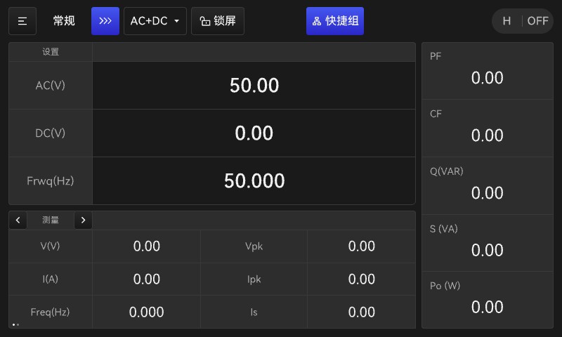
Figure 5.1.1 Standard Standby Screen
After the power supply self-test is complete, the system enters the standby screen. On this screen, you can use the touchscreen to adjust the settings for AC voltage, DC voltage, and frequency.
In this state, you can perform the following operations:
Use the ≡ button in the upper-left corner to select Normal or Programming mode, as well as to access General Settings and System Settings.
You can use the >>> key to configure parameters in normal mode.
Using the AC+DC button, you can select different output modes in normal operation, including AC+DC, AC, and DC.
Note: AC+DC: AC/DC superimposed mode; AC: AC mode; DC: DC mode.
To use the lock screen: When the screen is on, touches anywhere on the screen other than the lock button will have no effect; tap the lock button again to unlock.
You can configure and select output for shortcut groups using shortcut keys.
You can press the < and > keys on either side of the measurement key to view different measurement values.
2. Normal startup screen:
The human-computer interface is shown in Figure 5.1.2.
Figure 5.1.2 Human-Computer Interface



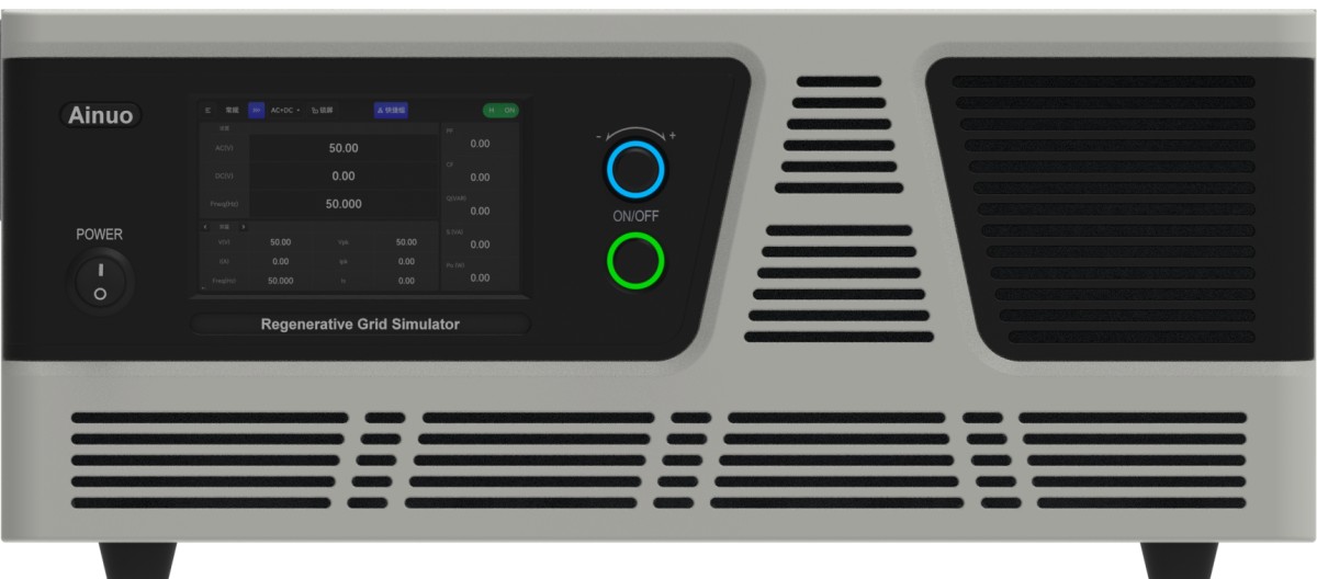
After setting the parameters, you can activate the output using the ON/OFF button on the front panel (the green button shown below in Figure 5.1.2). The ON/OFF button and the knob indicator lights will illuminate, and the display in the upper-right corner will change from “OFF” to “ON” and become brighter, indicating that the power supply is currently in test output mode. Output parameter values can be adjusted via the touchscreen or the rotary knob; refer to Section 3.3 in Chapter 3 for instructions on using the rotary knob. The display interface after the power supply is started is shown in Figure 5.1.3.
Note: When the output mode is AC+DC, overvoltage protection will be triggered if the set voltage exceeds the upper limit (see Table 5.1.1 for the upper limit).
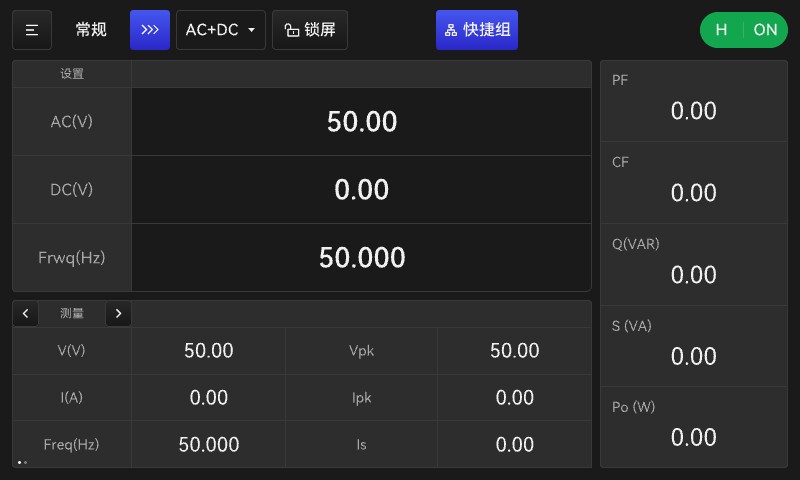
Figure 5.1.3 Standard Startup Screen
5.1.2 Normal/Programming Mode Selection Screen
Use the ≡ button in the upper-left corner to select Normal or Programming mode, as well as to access General Settings and System Settings. See Figure 5.1.4.
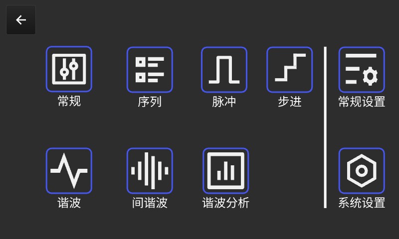
a. LSP-EMC Series Mode Selection Screen
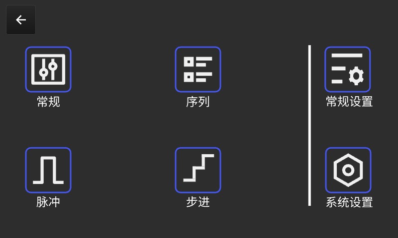
b. LSP-EMC(8) Series Mode Selection Screen
Figure 5.1.4 Mode Selection Screen
On this screen, you can use the touchscreen to select different output modes and settings.
5.1.3 General Settings Interface
1. Editing Parameters in Normal Mode
Use the >>> key to configure standard mode parameters; the interface displayed is shown in Figure 5.1.5.
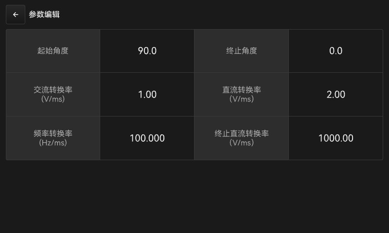
Figure 5.1.5 Editing Parameters in Standard Mode
On this screen, you can configure parameters such as the start angle, end angle, and conversion rate for output in standard output mode.
Start Angle: Controls the start angle of the output waveform, with a range of 0.0–359.9°.
Stop Angle: Controls the stop angle of the output waveform, with a range of 0.0–360.0°, where 0.0 indicates an immediate stop.
AC Conversion Rate: The voltage increase per millisecond as the voltage rises from 0 to the value set on the main screen.
DC ramp rate: The voltage increase per millisecond as the voltage rises from 0 to the value set on the main screen.
Frequency Ramp Rate: The rate at which the frequency increases from 0 to the main interface frequency, in 1-millisecond increments.
Termination DC Conversion Rate: The voltage drop per 1 ms as the voltage is reduced to 0 V from the value set on the main interface.
Use the “Waveform Settings” button on this screen to access the waveform settings screen, where you can select Waveform Mode A or Waveform Mode B. Waveform Modes A and B are selected in the system settings.
Selectable waveforms include sine wave (SINE), square-like wave (SQUA), triangle wave (TRIA), clamped sine wave (CSIN), and built-in waveforms DST1–DST30 (see Appendix II). As shown in Figure 5.1.6
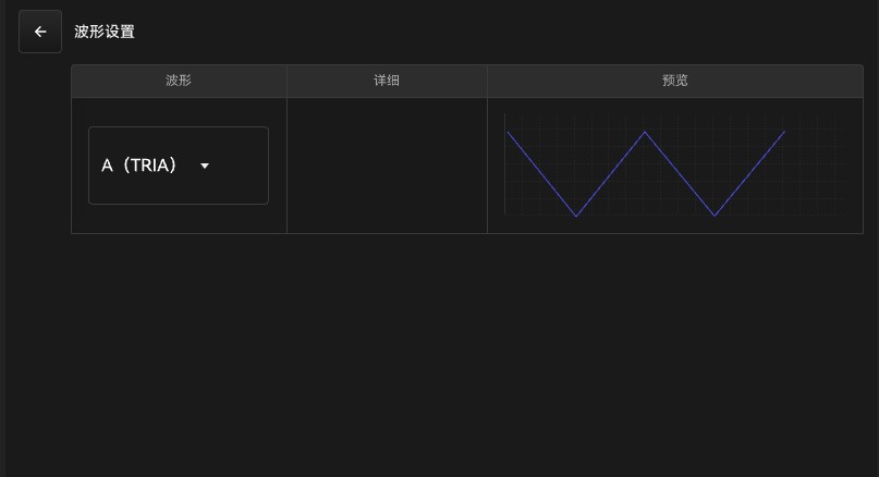
Figure 5.1.6 Normal Mode—Parameter Editor Waveform Settings
2. AC/DC Output Selection
Use the AC+DC button to select different outputs in Normal mode. When AC+DC output is selected, the main standby screen shown in Figure 5.1.1 appears; the DC and AC output screens are shown in Figure 5.1.7.
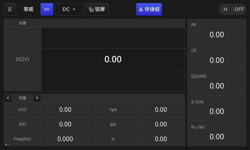
DC Output Interface
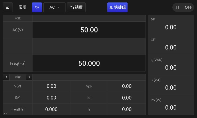
AC Output Interface
5.1.7 DC and AC Output Display Screen
When DC output is selected, only DC output parameters can be configured on this screen.
When AC output is selected, the interface allows only AC output parameters to be configured.
3. Quick Groups Feature
Configure the shortcut group using the shortcut group key to access the interface shown in Figure 5.1.8.
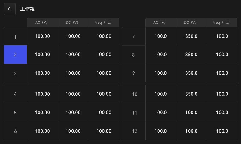
Figure 5.1.8: Shortcut Group Settings Interface
On this screen, you can save frequently used parameter sets—there are 12 sets in total—and use the page navigation buttons at the top to scroll through and select them. Once you’ve finished setting them up, select the desired quick-access group, then return to the output screen.
4. Measurement Display Area
This section displays a total of two pages of measurement results. You can use the < and > keys on either side of the measurement key to view different measurement parameters. The first page is shown in Figure 5.1.1, and the second page is shown in Figure 5.1.9.
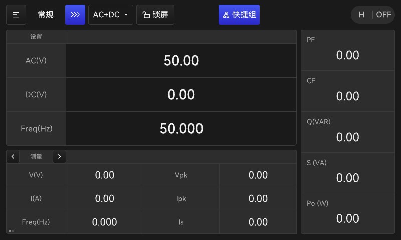
Figure 5.1.9 Measurement Area Display
Below the title bar:
AC (V): AC output set voltage;
DC (V): DC output voltage setting;
Frwq (Hz): AC output frequency setting;
Page 1:
V: Voltage measurement display;
I: Current measurement display;
Po: Active power display;
Vpk: Peak voltage;
Ipk: Peak current;
Is: Inrush current;
Page 2:
Vac: AC measurement voltage display;
Iac: AC measurement current display;
Vdc: Display of measured DC voltage;
Idc: DC measurement current display;
On the right side of the screen:
PF: Power factor display;
CF: Crest factor;
Q (VAR): Reactive power;
S (VA): Apparent power;
Po (W): Active power;
Meaning of specific parameter options:
Voltage Settings: The test power supply offers three output voltage settings: Auto, High, and Low:
The “Low” range indicates an output voltage range of 0–175 V. Note: When set to the “Low” range, AC and DC setpoints that exceed the “Low” range will be forced to the maximum value of the “Low” voltage range.
The high setting indicates an output voltage range of 0–350 V, but the current output capacity at this setting is half that of the low setting.
“Auto Mode” means that the power supply will automatically determine whether it is operating in high-range or low-range mode based on the set voltage value. When operating in low-range mode, the output voltage range is 0–175 V; in high-range mode, the output voltage range is 175–350 V.
See Table 5.1.1 for the voltage output ranges of each gear under different output modes. In the table, Vac represents the root mean square (RMS) value of the AC output voltage, and Vdc represents the DC output voltage.
Table 5.1.1 Voltage Output Range
| Output Range Output Method | Low-end | High-end |
| Alternating Current (AC) | 0.0 V–175.0 V | 0.0 V–350.0 V |
| Direct Current (DC) | -247.5 V to 247.5 V | -495.0 V to 495.0 V |
| AC + DC | Vac*1.414+|Vdc|≤247.5V | Vac*1.414+|Vdc|≤495V |
Note: When the gear mode is set to “Auto,” the step, sequence, and interharmonic output modes are unavailable; you must switch to “High” or “Low” to access them.
AC Voltage: AC voltage output setting, range: 0.0–350.0 V
Output Frequency: AC output frequency setting, ranging from 15.0 to 1000 Hz
DC Voltage: DC voltage output setting, with a range of -495.0 to 495.0 V
Output Modes: The test power supply offers three output modes: AC, DC, and AC+DC.
AC—AC mode, DC—DC mode, AC+DC—AC/DC combined mode.
Start Angle: Controls the start angle of the output waveform, with a range of 0.0 to 359.9°.
Stop Angle: Controls the stop angle of the output waveform, with a range of 0.0 to 360.0°, where 0.0 indicates an immediate stop.
Current Limit: The limit on the RMS value of the output current. If the actual output exceeds this value, a protection event will be triggered. The range is 0.0 to the lower rated current. Setting this value to 0.0 disables this function.
Over-Limit Delay: The delay time before protection is triggered when the actual output current exceeds the current limit, ranging from 0.0 s to 99.9 s.
When the output current exceeds the maximum current limit specified for the power supply, the over-limit delay time is disabled.
Waveform Selection: Sets the waveform of the output voltage; options include A, B, and several others. When the output is activated, the voltage waveform will be output according to the waveform type specified in “System Settings.”
5.2 Online Adjustment Function
5.2.1 Changes to Digital Inputs
When operating in normal mode, users can directly enter or adjust the power supply’s voltage and frequency output values without turning off the power. This operation is called online adjustment. When making changes via digital input on the screen, a soft keyboard pops up, as shown in Figure 5.2.1.
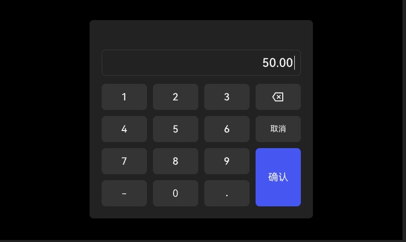
Figure 5.2.1 Digital Input Modification Interface
Online Adjustment Instructions: When selecting the appropriate online adjustment value, you can perform the adjustment using either the rotary knob or the on-screen numeric input. Adjustments made with the rotary knob directly change the output. After entering a value using the on-screen numeric input, press the “Confirm” button to accept the entry or the “Cancel” button to discard it. If the entered value falls within the permitted range for the setpoint, the online adjustment will be performed immediately; otherwise, no adjustment will be made.
5.2.2 Knob Changes
When parameter values change, you can also adjust the values using the front-panel knobs. To do so, follow these steps:
1) Press the knob button on the front panel; the knob will light up blue, indicating that the knob function is now active;
2) Select the parameter you want to adjust by tapping the touchscreen; an underline will appear beneath that parameter, and the front panel display will appear as shown in Figure 5.2.2;
Note: If there is no user input for 10 seconds, the knob will no longer be selected—that is, the underline will disappear.
3) At this point, press the knob again to select the digit you want to adjust, then turn the knob to change the parameter;
4) After touching the parameter again, the underline disappears; when you press the knob, the blue light turns off, and the knob function is disabled.
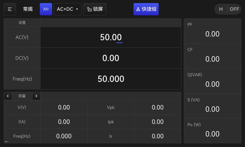
Figure 5.2.2 Knob Functions—Display Screen
5.3 General Settings
5.3.1 Restriction and Protection Settings
Use the ≡ button in the upper-left corner of the standby home screen to select General or Programming mode, as well as General Settings and System Settings. Selecting General Settings opens the General Settings menu, where you can configure voltage and frequency limit parameters, current and power protection thresholds, output waveform settings, and other options. The output limit settings are shown in Figure 5.3.1.
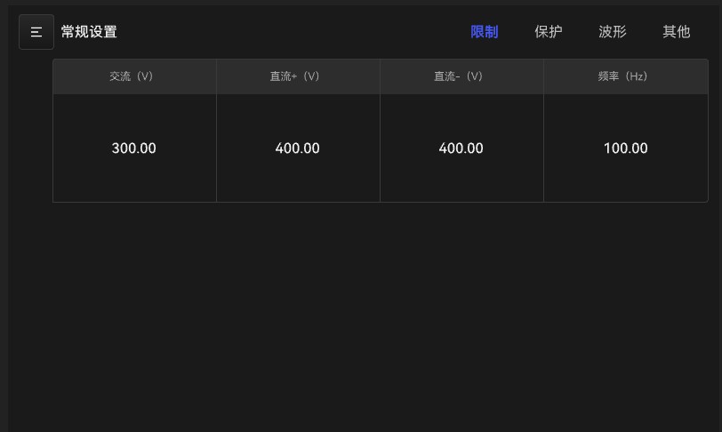
a. Limit value
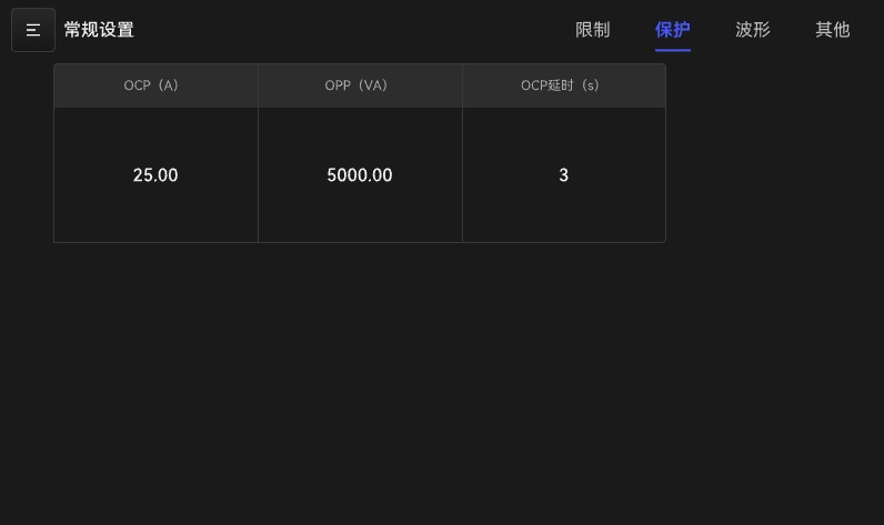
b. Protection value
Figure 5.3.1 Output Limit and Protection Value Settings
When setting limit values, the AC range is 0–350 V, the DC range is –495.0 to +495.0 V, and the frequency range is 15–1000 Hz;
When setting the protection value, the power supply is categorized by model, and the current setting range varies by model;
0.5 kW: 0–5 A, power setting range 0–500 VA;
1 kW: 0–10 A, power setting range 0–1000 VA;
2 kW: 0–20 A, power setting range 0–2000 VA;
4 kW: 0–40 A, power setting range 0–4000 VA;
6 kW: 0–60 A, power setting range 0–6000 VA;
(Note: The current values listed above are for the low range of AC; for the high range, divide by two. DC current values are half those of AC.)
5.3.2 Waveform Settings
Use the “Waveform” option to set the output voltage waveform; there are two options: A or B. When the output is activated, the voltage waveform will be output according to the waveform type customized in “Waveform Settings.” This interface allows you to set waveforms separately for both A-mode and B-mode. This selection ultimately determines the output waveform under “General Output—Parameter Edit.” The settings interface is shown in Figure 5.3.2.
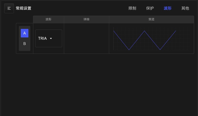
Figure 5.3.2 System Settings—Waveform Settings
On this screen, you can select different output waveforms using the drop-down menu to the right of “A/B.”
··5.3.3 Other Settings
Under default settings, selecting another key displays the interface shown in Figure 5.3.3.a.
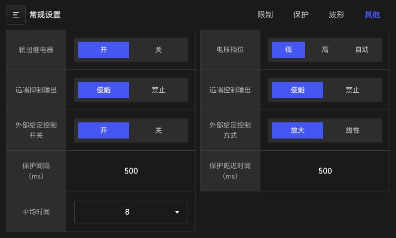
Figure 5.3.3.a General Settings and Other Settings
With this setting, you can perform the following operations:
1) Output Relay Control: The power supply is connected to the load via an output relay. When “On” is selected, the output relay is normally closed; when “Off” is selected, the output relay is closed at startup and opened when the system is shut down.
2) High/Low/Auto Settings: There are three settings: High, Low, and Auto. High voltage range: 0–350 V; Low voltage range: 0–175 V; Auto: Voltage settings of 175 V or less are classified as Low, and those above 175 V are classified as High.
3) Remote Inhibit Output: When the remote control function is not set to “Off,” the power supply can receive control signals from the rear-panel TTL interface. “TRIG” indicates that when the TTL signal is at a low level, the AC test power supply will shut off its output; if the TTL signal returns to a high level, the power supply will remain in this state, and the user must press the start button to resume the AC power supply’s output;
4) Remote Control Output: When the remote inhibit function is off, the power supply can receive control signals from the rear-panel TTL interface. When remote control is enabled, pressing the output button first enters the “wait” state; whether an output is generated in this state depends on the high or low level of the external TTL signal. Pressing the output button again returns the unit to the “off” state. In the “wait” state, “wait” appears in orange in the upper-right corner of the screen, and the button indicator flashes green. See Figure 5.3.3.b for the control logic.
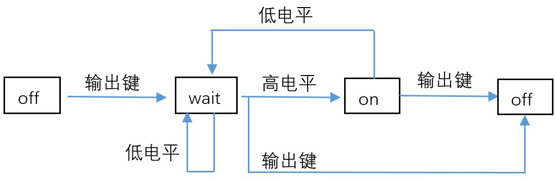
Figure 5.3.3.b: Logic Block Diagram of the Remote Control Function
External Input Signal Control: Enables or disables the external input signal control function; when enabled, the device can receive externally supplied signals.
External Input Signal Control Mode: Linear/Amplified.
1. In linear mode, the external input signal is DC; the output voltage is controlled solely by the external input voltage and is amplified in direct proportion to the external DC input voltage.
Low side: Vout (AC) = |Vref| / 10 Vdc * 175 V
High Side: Vout (AC) = |Vref| / 10 Vdc * 350 V
2. In amplification mode, the external input signal is either AC or DC, and the power supply output voltage is the sum of the set voltage and the amplified external input voltage.
Low Level: Vout (DC) = Vref (DC) / 10 Vdc * 247.5 V
Vout (AC) = Vref (AC) / 7.072 Vac × 175 V
High: Vout (DC) = Vref (DC) / 10 Vdc * 495 V
Vout (AC) = Vref (AC) / 7.072 Vac * 350 V
7) Protection interval: 0.0 ms to 999.9 ms, representing the time elapsed from the start of the measurement to its completion.
8) Protection delay time: 0.0 ms to 999.9 ms. In the measurement data, “Is” refers to the surge current test result; the protection delay time indicates the time elapsed from the voltage output until the start of the Is measurement.
9) Average Time: Indicates the number of samples used to calculate the displayed measurement value. In cases where the measurement value fluctuates significantly, a higher number of samples can be set to improve the accuracy of the measurement. The available settings are 1, 4, 8, 16, and 32.
When the LSP-EMC series AC test power supply outputs DC voltage, the main differences from a typical DC power supply are as follows: 1. Because it lacks an output filter capacitor, its output ripple is relatively high. 2. When the output current reaches the current limit, the output voltage is immediately cut off and the unit enters a protection state, unlike the constant-current mode of typical DC power supplies, which merely reduces the output voltage. 3. Large-capacity electrolytic capacitors (>20 μF) must not be connected to the output terminals to prevent damage to the power supply caused by output instability. |
To overcome the shortcomings described in items 1 and 3 above, it is recommended that a device be added to the output to provide better performance and protection.
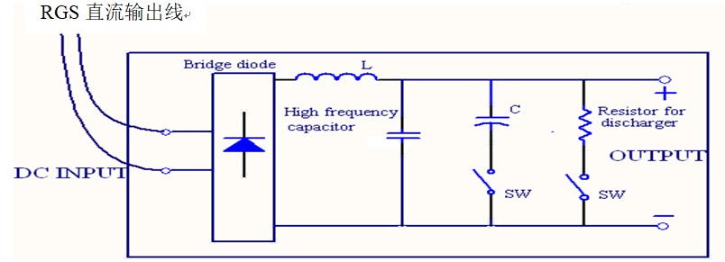
Note:
1. Bridge diode: Prevents output instability caused by capacitance at the output terminal and prevents damage to the device under test resulting from accidental AC voltage or reverse polarity;
2. L and high-frequency capacitor: The combination of an inductor and a capacitor can filter out high-frequency voltage ripple;
3. C and SW: C refers to a high-capacity electrolytic capacitor; this component may be added if it is not present at the test object end. If it is already present at the test object end, use SW (switch) to turn it off;
4. Discharge Resistor and SW: The discharge resistor discharges residual charge from the output terminal or the device under test to prevent hazards. The SW (switch) can be used to discharge the charge when necessary. It is important to select a discharge resistor with sufficient power capacity to fulfill this function.
5.4 System Settings Features
5.4.1 Basic Settings
Tap the ≡ icon in the upper-left corner of the main screen to access the system settings. After selecting the system settings option, the screen shown in Figure 5.4.1 will appear.
This settings menu includes four window options: Basic, Interface, Status, and Information.
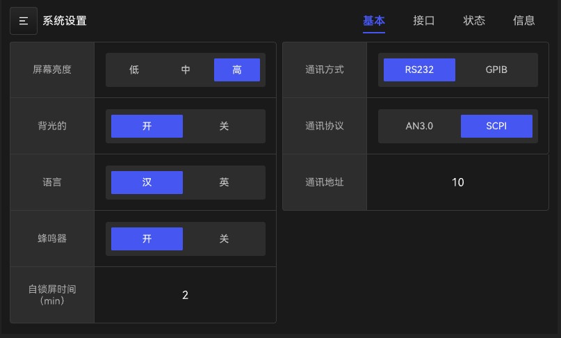
Figure 5.4.1 System Settings Function Selection Screen
After entering the system settings interface, you are taken to the Basic Options page by default. This page is primarily used to configure basic power settings.
Screen Brightness: Adjust the display brightness using three settings: Low, Medium, and High.
Communication Options: Standard RS485, RS232 (optional), and GPIB (optional).
Backlight: On/Off—Adjusts the display clarity.
Communication Protocols: LSP 3.0 and SCPI; see Appendix I for details on both protocols.
Language: Chinese, English—select the display language on the interface
Mailing Address: Range 1–255
Buzzer: When enabled, tapping the screen will produce a buzzer sound; when disabled, the sound for touchscreen operations will be turned off.
Auto-Lock Time: Sets the time before the screen turns off when the device is idle.
5.4.2 Interface Settings
In System Settings, select the page containing the Interface options, as shown in Figure 5.4.2.
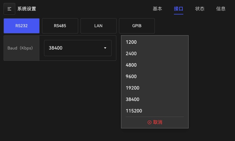
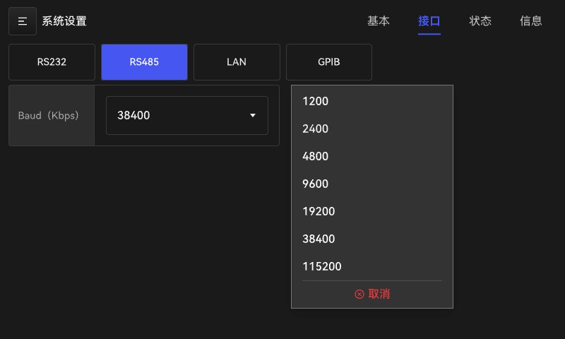
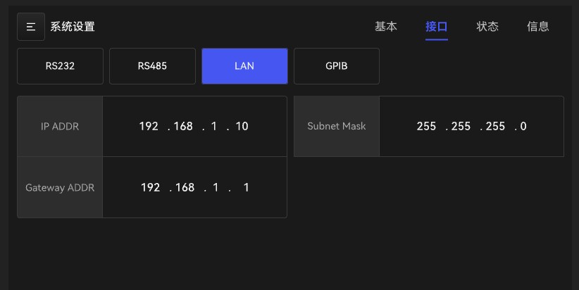
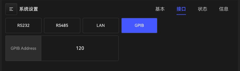
Figure 5.4.2 Interface Settings
RS485 and RS232 baud rates: 1200, 2400, 4800, 9600, 19200, 38400, 115200.
GPIB: Communication addresses 1–255.
LAN: You can change the gateway address to establish communication.
5.4.3 Status Settings
In System Settings, select the page containing the Status options, as shown in Figure 5.4.3.
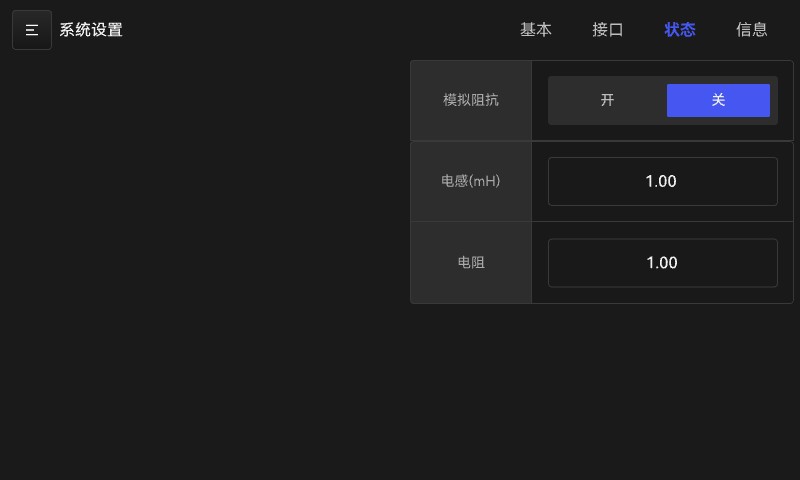
Figure 5.4.3 Status Settings
Analog Impedance: On/Off; Enables the analog impedance function, allowing the test power supply’s output impedance to be programmed.
Resistance: Simulates the power supply output resistance, with a range of 0.00–1.00 Ω
Inductance: Analog power supply output inductance, range 0.00–1.00 mH
5.4.3 Information Interface
Select the page containing the information options, as shown in Figure 5.4.4.
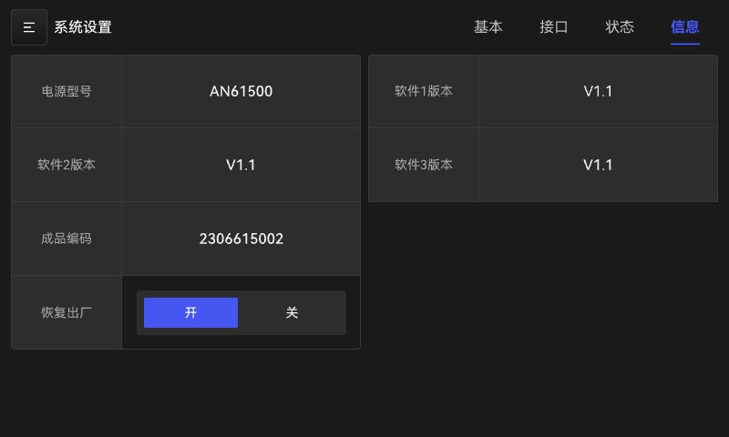
Figure 5.4.4 Information Interface
This interface includes information such as the power supply model, version, and code.
Restore to Factory Settings: Restores the system to its default factory settings.
5.5 Sequence Testing Features
5.5.1 Standby Screen for Sequence Test Function
The output waveform for the sequence test mode consists of all possible combinations of sequence number configurations. The output waveform begins with sequence number 0 and proceeds sequentially according to the sequence number configurations until the run length of a sequence number reaches 0; at that point, the output stops, and the configurations for subsequent sequence numbers are not executed. Users can edit the sequence of output voltages as needed.
Tap the ≡ button in the upper-left corner of the main screen to select Sequence Mode. This will take you to the Sequence Mode standby screen, as shown in Figure 5.5.1.
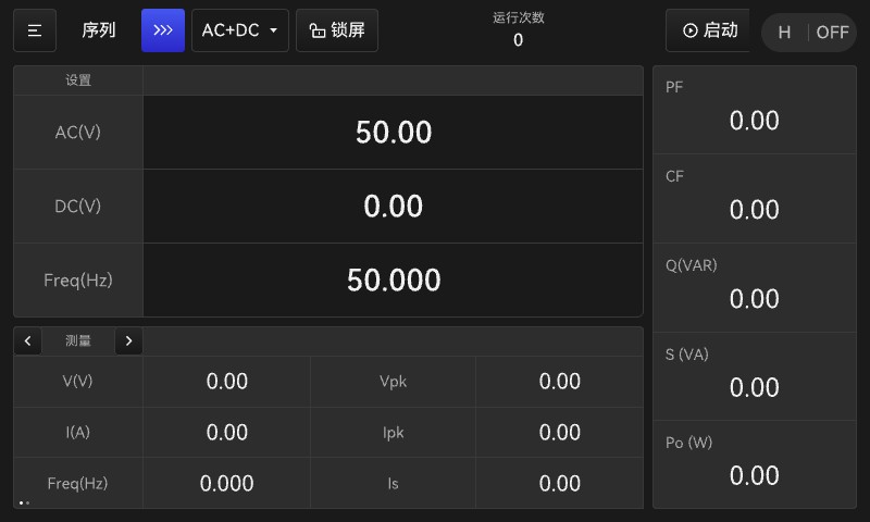
Figure 5.5.1: Sequence Mode Standby Screen
This screen differs from the standard standby screen in that the title normally displayed in the upper-left corner has been replaced by “Sequence.” Tapping the >>> button to the right of this display option will take you to the parameter editing screen for sequence mode.
In addition, a start button appears to the left of the “OF/OFF” display area in the upper-right corner of the interface. This button is used to enter programming mode. Once programming mode is activated, the start button becomes a stop button; clicking it again will turn off the power output.
The “Number of Runs” label displays the number of times the current loop sequence has been tested. The range is 0–9999.
Note: The AC, DC, and Frwq parameters set on this screen are standard parameters and are unrelated to the parameters in the sequence test mode.
5.5.2 Editing Parameters for Sequence Testing Functions
On the sequence standby screen, tap the >>> button to the right of the sequence title to enter the sequence mode parameter editing screen. See Figure 5.5.2.
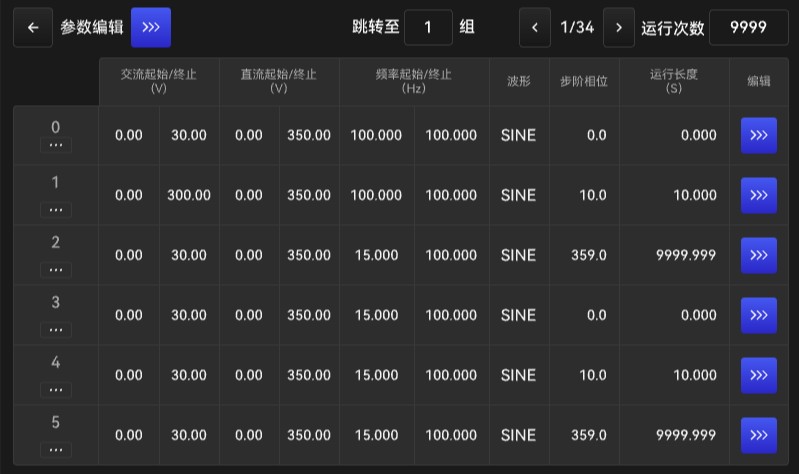
Figure 5.5.2 Editing Sequence Function Parameters
1. Sequence Group Shortcut Features
In the interface shown in Figure 5.5.2, the numbers 0, 1, 2, … on the far left represent sequence group numbers. Clicking the … button below the numbers allows you to perform four operations: copy, paste, insert, and delete. As shown in Figure 5.5.3.
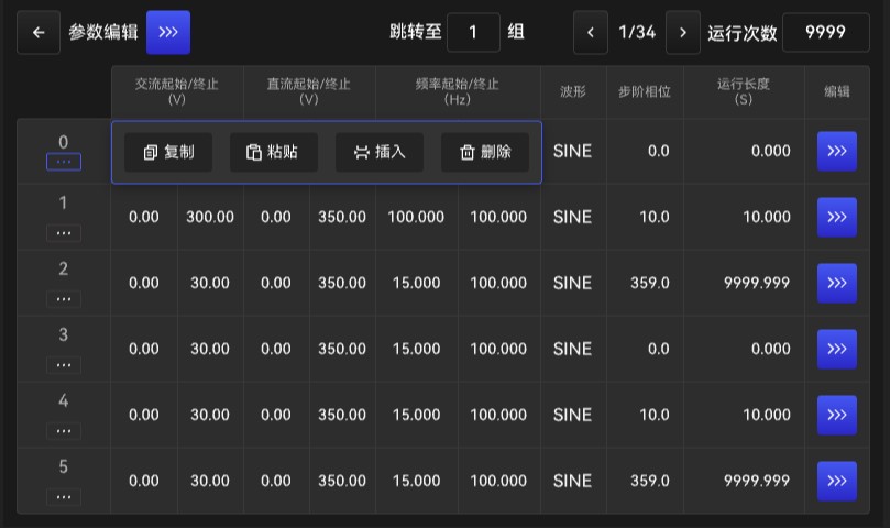
Figure 5.5.3 Sequence Group Shortcuts
Note: All four of the above operations apply to all parameters in the sequence group. For three-phase systems, these four operations are performed simultaneously on the U, V, and W phases. For single-phase systems, the operation is performed on a single sequence number.
2. Function for editing sequence output parameters
On the interface shown in Figure 5.5.2, parameters such as AC start/stop voltage, DC start/stop voltage, start/stop frequency values, output waveform format, step phase, and run length can be displayed.
Use the >>> button in the editing bar on the far right to enter the interface editing screen and modify the parameters shown above, as illustrated in Figure 5.5.4.
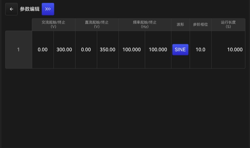
Figure 5.5.4 Parameter Editing
Note: On this screen, when the start and end values are the same, you can click the “Start/End” button at the top to edit both values simultaneously.
In this interface, the waveform bar allows you to select the output waveform format. Click the clickable item below the waveform bar to access the waveform settings interface for sequence mode, as shown in Figure 5.5.5.
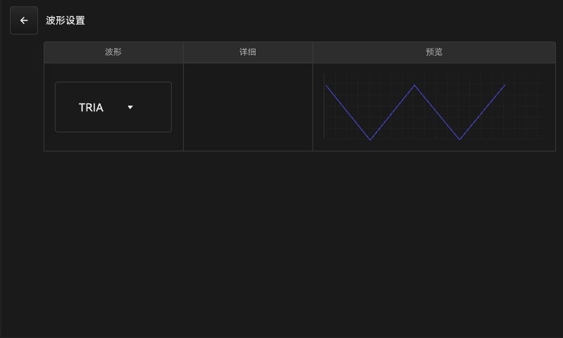
Figure 5.5.5 Sequence Mode—Waveform Settings
This interface allows you to select an output waveform. There are two quick-select waveforms (A and B) and a total of six output waveforms to choose from. After making your selection, click the ← button to save your choice and return.
3. Additional parameter settings for sequence functions
On the interface shown in Figure 5.5.2, click the >>> button to the right of “Parameter Edit” to access additional parameter settings for sequence mode, as shown in Figure 5.5.6.
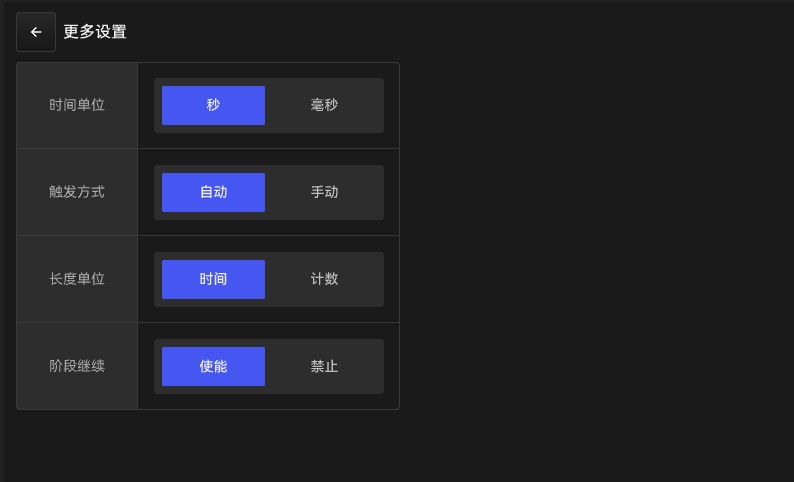
Figure 5.5.6: Additional Parameter Settings for Sequence Functions
Time unit: seconds/milliseconds. This is the time unit used in edit sequence mode for the run length.
Trigger Mode: Automatic/Manual. Manual/Automatic: “Manual” means that only one sequence of waveforms is executed after triggering, which has the same effect as setting the number of cycles to 1; “Automatic” means that all specified cycles will be completed after triggering.
Unit of Length: This option configures how the runtime is measured in the serial number configuration settings. “Time”: Runtime is measured in time; “Period”: Runtime is measured in terms of the number of periods of the current waveform;
“Sequence Continuation”: When this feature is disabled, each sequence group starts at the set angle. When this feature is enabled, the starting angle of each sequence group is the ending angle of the previous sequence group.
4. Meanings of Specific Parameter Options
Number of iterations: 0–9999; 0 indicates an infinite loop;
Trigger Mode: Manual/Automatic. “Manual” means that the sequence waveform is executed only once after triggering, which has the same effect as setting the number of cycles to 1; “Automatic” means that all cycles will be completed after triggering.
Unit of Length: This option configures how the runtime is measured in the serial number configuration settings. “Time”: Runtime is measured in time; “Period”: Runtime is measured in terms of the number of periods of the current waveform;
Sequence Group Number: 0–99; supports editing of 100 variations; you can navigate between sequence groups using the navigation options at the top of the interface shown in Figure 5.18.
Runtime: 1–9999. If the unit of length is “time,” the unit is ms or s; if the unit of length is “cycle,” the unit is 1 or K, where K represents *1000;
Unit of Measurement: This option configures the unit of time for the runtime. If the length unit is “time,” you can select ms or s; if the length unit is “cycle,” you can select 1 or K;
AC Initial: The AC voltage at the start of the current sequence number, 0.0–350.0 V;
Initial Frequency: The AC frequency at the start of the current sequence number, 15–1000.0 Hz;
Initial DC: The DC voltage at the start of the current serial number, -495.0 to 495.0 V;
AC Termination: The AC voltage at the end of the current sequence, 0.0–350.0 V;
Frequency Limit: The AC frequency at which the current sequence number ends, 15–1000.0 Hz;
DC Termination: The DC voltage at the end of the current sequence, -495.0 to 495.0 V;
Waveform Selection: The output waveform configured for the current serial number; when output is enabled, the voltage waveform will be output according to the waveform type customized in “System Settings.”
Step Phase: The phase angle at the start of the current sequence number, 0.0–359.9;
5.5.3 Operational State of the Sequence Testing Function
The standby screen for the sequence test function is shown in Figure 5.5.1. Click the Start button on the standby screen to begin the test, as shown in Figure 5.5.7.
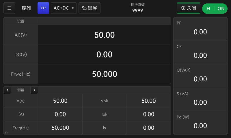
Figure 5.5.7: Sequence Test Function in Operation
Once Sequence Mode is activated, to turn off the output, press the Start button in the upper-right corner of the display, or use the ON/OFF button on the front panel. The measurement display area remains the same as in Normal Mode.
Note: The AC, DC, and Frwq parameters displayed on this screen are standard-mode parameters. Once sequence mode is enabled, only the parameters set during sequence mode parameter editing will be output.
Note: Sequence mode can only be activated using the “Start” button in the upper-right corner of the standby screen. To stop the mode, you can either use the “Stop” button in the upper-right corner or press the physical ON/OFF button on the front panel to turn off the output. If, in programming mode, you use the physical ON/OFF button on the front panel to turn on the power, the output will default to normal mode—that is, the parameters set on the main screen. At this point, you can also tap the Start button on the display again to enter programming mode.

5.6 Pulse Output Function
5.6.1 Pulse Output Function Standby Screen
The pulse output mode allows users to edit pulse output waveforms to simulate voltage fluctuations and sags in the power grid, as well as to generate spikes and notches.
Tap the ≡ button in the upper-left corner of the main screen to select Pulse Mode. This will take you to the Pulse Mode standby screen, as shown in Figure 5.6.1.
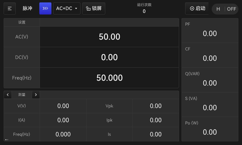
Figure 5.6.1 Pulse Standby Screen
The display screen is identical to the sequence standby screen, except for the “Pulse >>>” button in the upper-left corner.
Note: The AC, DC, and Frwq parameters set on this screen are standard parameters and are unrelated to the parameters in the sequence test mode.
5.6.2 Editing Pulse Output Function Parameters
1. Parameter Editing
Click the “Pulse >>>” button to enter the parameter editing interface for pulse output mode, as shown in Figure 5.6.2.
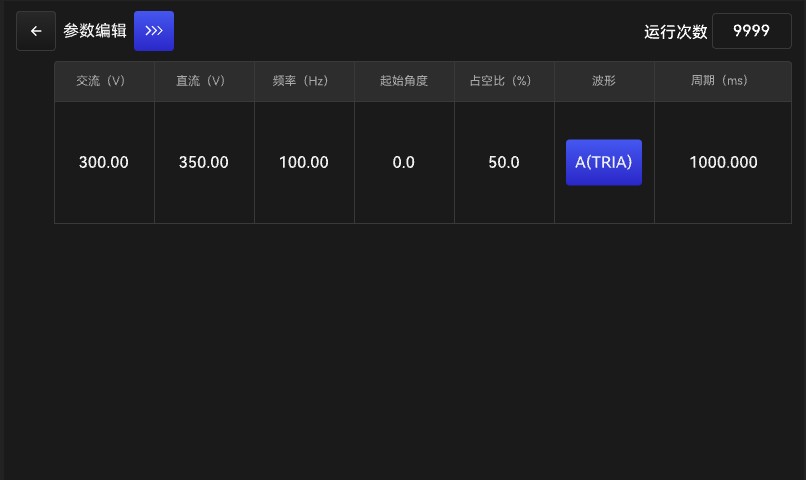
Figure 5.6.2 Pulse Output Mode Parameter Editing Interface
Unlike the sequence mode, where you must return to the parameter editing screen to make changes, the parameters for the pulse output mode can be edited directly on screen 5.6.2.
In addition, click the waveform selection bar to select a waveform; the setup procedure is the same as for waveform selection in the Sequence Test function described in Section 5.5.2.
Click the >>> button to the right of “Parameter Edit” in the upper-left corner of Figure 5.6.2 to access the additional settings screen for pulse output mode, as shown in Figure 5.6.3.
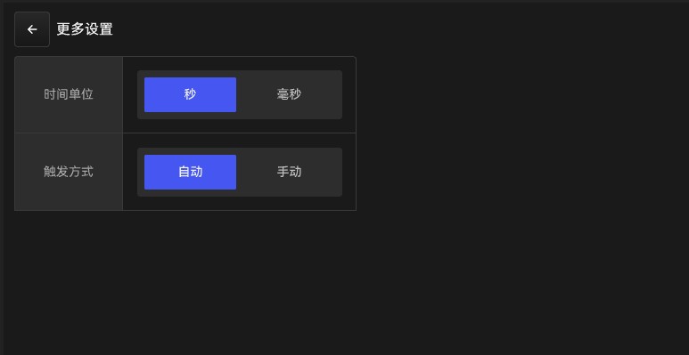
Figure 5.6.3 Additional Pulse Mode Settings
2. Meanings of Specific Parameter Options
Number of Cycles: The number of times the pulse cycle is repeated, ranging from 0 to 9999. A value of 0 indicates an unlimited number of cycles until the output is manually stopped.
AC: The AC voltage value of the pulse output, ranging from 0.0 to 350.0 V
Frequency: Pulse output frequency, ranging from 15 to 1000 Hz
DC Voltage: The DC voltage value of the pulse output, ranging from -495.0 to 495.0 V
AC Differential: The AC voltage difference between adjacent pulses, 0–350.0 V;
Frequency difference: The difference in frequency between adjacent pulses, 0–100.0 Hz;
DC difference: The DC voltage difference between adjacent pulses, -495.0 to 495.0 V;
Duty Cycle: The duty cycle of the pulse output waveform over its entire period, ranging from 0 to 100 percent
Represents the percentage of time that the pulse waveform occupies within an output cycle
Cycle: Output cycle, ranging from 1 to 9999, representing the duration of one output cycle. Units: ms, s
Trigger Mode: Manual or Automatic. “Manual” means the output stops after a single cycle; “Automatic” means the output will continue for the number of cycles specified under “Number of Cycles” until the count is complete.
Start Angle: The phase angle of the output pulse waveform, ranging from 0.0 to 359.9
Waveform Selection: When a trigger pulse is output, the pulse voltage waveform will be output according to the waveform type specified in “System Settings.”
Time units: Output period units: ms, s
5.6.3 Pulse Output Function Operating Mode
Press the Start button on the pulse output mode standby screen to activate pulse output and display the number of operations in real time, as shown in Figure 5.6.4.
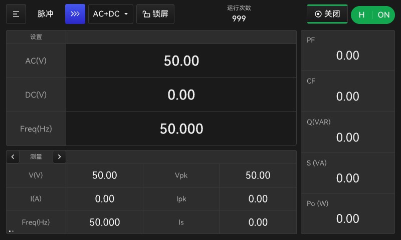
Figure 5.6.4 Operating State of Pulse Output Mode
Once pulse mode is activated, to turn off the output, press the Start button in the upper-right corner of the display, or use the ON/OFF button on the front panel. The measurement display area remains the same as in normal mode.
Note: The AC, DC, and Frwq values displayed on this screen are standard-mode parameters. Once pulse mode is activated, only the parameters set in the pulse mode parameter editor will be output.
Note: Pulse mode can only be activated using the “Start” button in the upper-right corner of the standby screen. To stop it, you can either press the “Stop” button in the upper-right corner or use the physical ON/OFF button on the front panel to turn off the output. If, in programming mode, you use the physical ON/OFF button on the front panel to turn on the power, the unit will operate in standard mode. At this point, you can tap the Start button on the display again to enter programming mode.

5.6.4 Examples of Pulse Parameter Settings
According to the test standards, a certain piece of equipment must have a 220 V, 50 Hz output that runs for 9 seconds, stops for 6 seconds, and automatically repeats this cycle 50 times. It can be configured using the following parameters:
| Operating Parameters | Key Parameter Settings |
| Pulse Parameters (Figure 5.23) | AC voltage: 220 V, output frequency: 50 Hz, duty cycle: 40%, cycle time: 15 s, time unit: s, number of operations: 50 |
| Pulse Parameters (Figure 5.24) | Time unit: s Trigger method: Automatic |
5.7 Stepper Test Function
5.7.1 Step Test Function Standby Screen
The step test mode provides a simple, automatic switching function to change the output voltage in steps rather than gradually. You can set the initial output voltage, the number of steps, and the duration at each step. Once the changes are complete, the output voltage will remain at the final output level.
Tap the ≡ button in the upper-left corner of the main screen to select step mode. This will take you to the step mode standby screen, as shown in Figure 5.7.1.
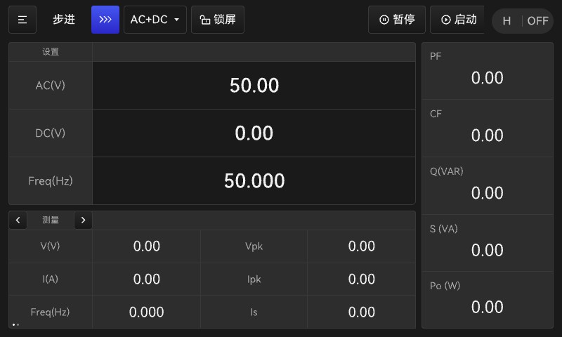
Figure 5.7.1 Step Mode Standby Screen
Compared to the standard standby screen, this interface includes a pause button and a start button. These buttons are used to initiate the step-by-step test function and to pause the operation once it has started.
Note: The AC, DC, and Frwq parameters set on this screen are standard parameters and are unrelated to the stepper test mode parameters.
5.7.2 Editing Parameters for the Step Test Function
1. Editing Parameters for the Step-by-Step Test Function
Tap the “Step >>>” button on the standby screen shown in Figure 5.7.1 to configure the parameters for the step test function. See Figure 5.7.2.
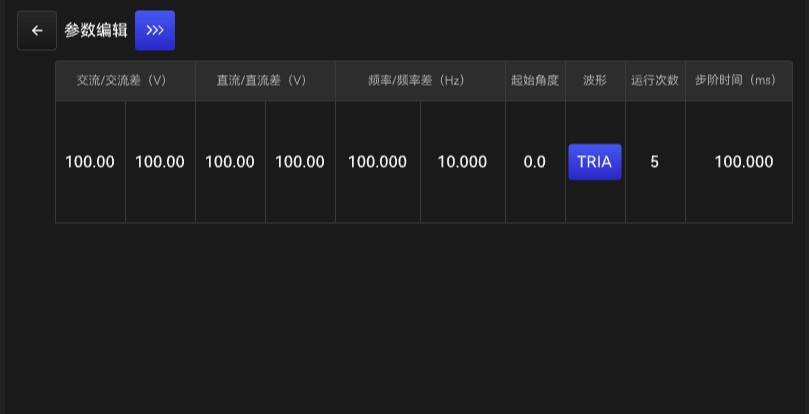
Figure 5.7.2 Editing Step Parameters
You can modify parameters directly in this interface. For parameters in the waveform bar, the procedure for changing them is the same as for waveform selection in the Sequential Test function described in Section 5.5.2.
On the interface shown in Figure 5.7.2, click the Parameter Edit >>> button to access the additional settings for the step test function. See Figure 5.7.3.
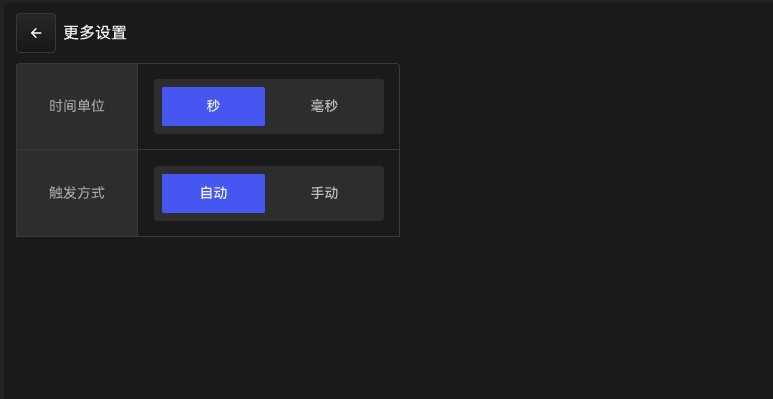
Figure 5.7.3 Additional Parameter Settings for the Step Test Function
2. Explanation of specific parameter options:
Number of Runs: The number of times each variation is executed, 0–9999;
Step Duration: The duration of each step, 1–9999;
AC: The initial AC voltage that triggers the step test output, 0.0–350.0 V;
Frequency: The initial frequency when triggering the step test output, 15–1000.0 Hz;
DC: The initial DC voltage when triggering the step test output, -495.0 V to 495.0 V;
AC difference: The difference in AC voltage between adjacent steps, 0–350.0 V;
Frequency difference: The difference in frequency between adjacent steps, 0–9984.0 Hz;
DC difference: The DC voltage difference between adjacent steps, -495.0 to 495.0 V;
Start Angle: The starting phase angle of the output for each step, 0.0–359.9;
Waveform Selection: Select a waveform; when the output is activated, the voltage waveform will be output according to the waveform type specified in “System Settings”;
Trigger Mode: Automatic/Manual. In automatic mode, once the stepped output is triggered, it will execute according to the number of steps. During the triggering process, you can use the pause button to pause or resume the current change process; manual mode means the output stops after a single cycle.
Time unit: ms/s, the unit used to determine the step time;
5.7.3 Operational State of the Step-by-Step Test Function
Press the Start button on the step-by-step test mode standby screen to activate step-by-step mode output, as shown in Figure 5.7.4.
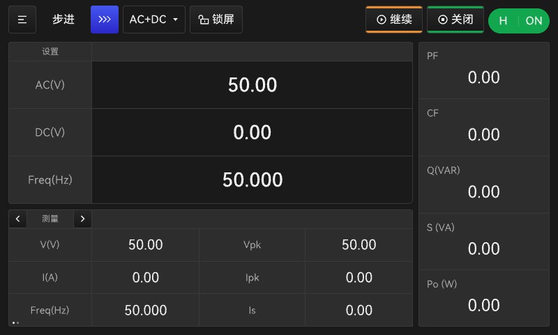
Figure 5.7.4: Step-by-Step Test Function in Operation
Once step mode is activated, to turn off the output, press the Start button in the upper-right corner of the display, or use the ON/OFF button on the front panel. The measurement display area remains the same as in normal mode.
In addition, you can pause or resume the output of the step test function using the pause button in the upper-right corner of the display.
Note: The AC, DC, and Freq parameters on this screen are for normal operation. Once pulse mode is enabled, only the parameters set during step mode parameter editing will be output.
Note: Step mode can only be activated using the Start button in the upper-right corner of the standby screen. To stop the mode, you can either press the Stop button in the upper-right corner or use the physical ON/OFF button on the front panel to turn off the output. If, in programming mode, you use the physical ON/OFF button on the front panel to turn on the power, the output will default to normal mode. At this point, you can tap the “Start” button on the display again to enter programming mode.

5.8 Harmonic Test Function (LSP-EMC Series Only)
5.8.1 Standby Screen for the Harmonic Test Function
The harmonic test function allows users to edit synthetic harmonic waveforms for up to 50 harmonics, as well as to adjust the output phase and harmonic content of each harmonic, thereby simulating waveform distortion in the output voltage and enabling the generation of special waveforms.
You can select harmonic mode by tapping the ≡ button in the upper-left corner of the main screen. This takes you to the harmonic mode standby screen, as shown in Figure 5.8.1.
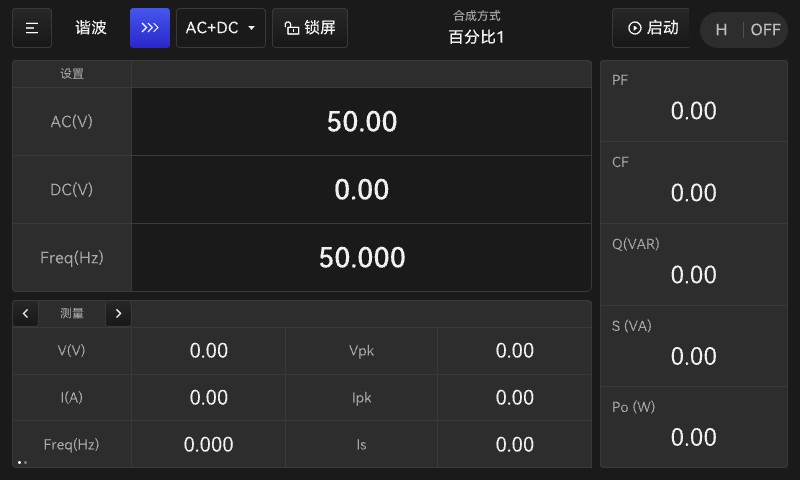
Figure 5.8.1 Harmonic Function Standby Screen
This interface appears essentially the same as the standard display interface, with the exception that it includes an additional display mode.
5.8.2 Editing Parameters for the Harmonic Test Function
1. Editing Parameters for the Harmonic Test Function
Tap the “Harmonics >>>” button on the standby screen shown in Figure 5.8.1 to configure the parameters for the harmonic synthesis function. See Figure 5.8.2.
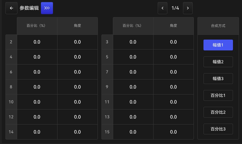
Figure 5.8.2 Editing Parameters for the Harmonic Synthesis Function
On this interface, the numbers 2, 3, 4, 5, 6, 7, 8, … on the left represent the nth-order harmonic components; you can configure the parameters for these harmonic components in their corresponding rows. Use the < and > buttons at the top to navigate through the pages; there are settings for a total of 40 harmonics.
On the right are six preset harmonic synthesis modes (equivalent to quick-access groups). Once the settings for each synthesis mode are complete, you can save them to use as quick-access groups for the harmonic synthesis function. The “Amplitude 1” through “Amplitude 3” options directly superimpose a voltage amplitude onto the fundamental voltage by setting the amplitude, thereby achieving waveform distortion. The “Percentage 1” through “Percentage 3” options superimpose a harmonic component equal to the fundamental voltage multiplied by the specified percentage onto the fundamental voltage, thereby achieving waveform distortion.
Note: The AC, DC, and Frwq parameters set on this screen are standard operating parameters and are unrelated to the parameters in harmonic test mode.
2. Fundamental Wave Parameter Settings
In the interface shown in Figure 5.8.2, click the Parameter Edit >>> button to access the settings for fundamental voltage, frequency, and other parameters. See Figure 5.8.3.
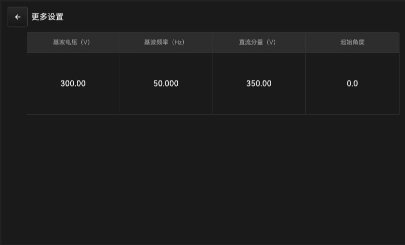
Figure 5.8.3 Fundamental Frequency Parameter Settings
3. Explanation of specific parameter options:
Synthesis Mode: You can select the waveform synthesis mode (which is equivalent to 6 memory groups): amplitude-based or percentage-based.
Fundamental Voltage: The fundamental AC voltage value, 0–350 V
Fundamental Frequency: The fundamental output frequency, ranging from 50 Hz to 60 Hz
DC Component: Outputs an additional DC voltage value in the range of -495.0 to 495.0 V
Start Angle: The start angle of the output waveform, ranging from 0 to 359.9°
xth Harmonic Amplitude/Percentage: The amplitude or percentage of the xth harmonic. For practical reasons and to comply with the power limits of AC power supplies, the power supply limits the composite value or the percentage per order. For harmonics from the 2nd to the 50th, the amplitude must be ≤90 V or the percentage must be ≤30%.
xth harmonic angle: Starting angle of the xth harmonic, ranging from 0 to 359.9°
Note: When settings exceed the specified range (e.g., when standard AC+DC parameter limits are exceeded, or when the fundamental voltage and DC component limits in the harmonic synthesis settings are exceeded, an overvoltage alarm will be triggered; please adjust the parameters so they do not exceed the limits before attempting to proceed).
5.8.3 Operational Status of the Harmonic Test Function
Click the Start button on the Stepper Harmonic Mode Standby screen to activate harmonic synthesis mode output; the runtime screen is shown in Figure 5.8.4.
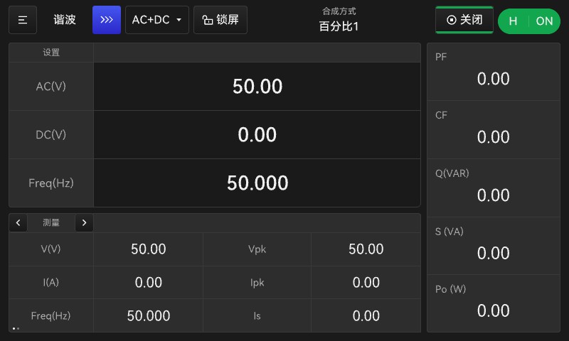
Figure 5.8.4: Harmonic Test Function in Operation
Once harmonic mode is activated, to turn off the output, press the Start button in the upper-right corner of the display, or use the ON/OFF button on the front panel. The measurement display area remains the same as in normal mode.
A shortcut group number for the compositing mode can be displayed at the top of the screen.
Note: The AC, DC, and Frwq parameters displayed on this screen are standard-mode parameters. Once harmonic mode is enabled, only the parameters set in the harmonic mode parameter editor are output. The harmonic parameters are superimposed on the fundamental parameters.
Note: The harmonic mode can only be activated using the “Start” button in the upper-right corner of the standby screen. To stop the mode, you can either use the “Stop” button in the upper-right corner or press the physical ON/OFF button on the front panel to turn off the output. If, in programming mode, you use the physical ON/OFF button on the front panel to turn on the power, the unit will operate in standard mode. In this case, you can tap the Start button on the display again to enter programming mode.

5.9 Interharmonic Test Function (LSP-EMC Series Only)
5.9.1 Standby Screen for Interharmonic Testing Function
In the interharmonic output mode, in addition to providing standard voltage output, another frequency-variable voltage component can be superimposed for use in certain anti-interference tests.
Use the ≡ button in the upper-left corner of the main screen to select the interharmonic mode, which takes you to the interharmonic mode standby screen, as shown in Figure 5.9.1.
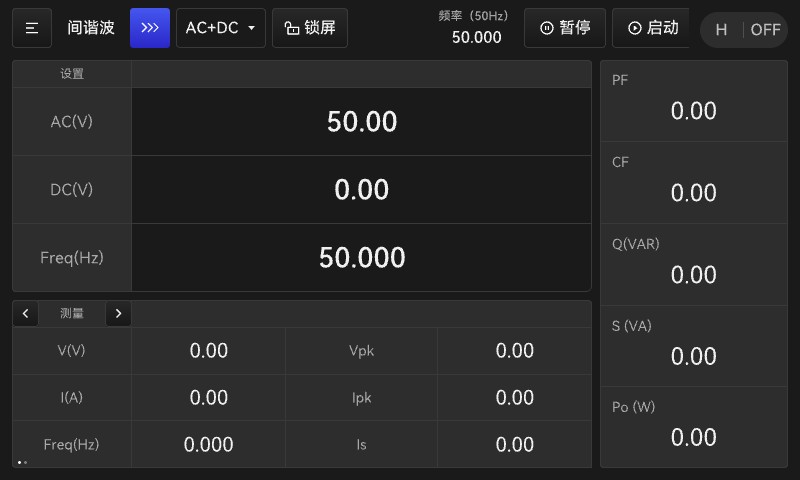
Figure 5.9.1 Standby Screen for the Interharmonic Test Function
The interharmonic standby screen differs from the standard standby screen in that it features a new frequency display, a pause button, and a play button at the top of the screen.
New Frequency Display: Shows the current operating frequency, ranging from 0.001 to 1000 Hz
Pause button, used to pause or resume interharmonic output.
Note: The AC, DC, and Frwq parameters set on this screen are standard parameters and are unrelated to the parameters for the interharmonic test mode.
5.9.2 Editing Interharmonic Function Parameters
1. Editing Interharmonic Function Parameters
In the interface shown in Figure 5.9.1, click the “Interharmonics >>>” button to access the interharmonic parameter settings, as shown in Figure 5.9.2.
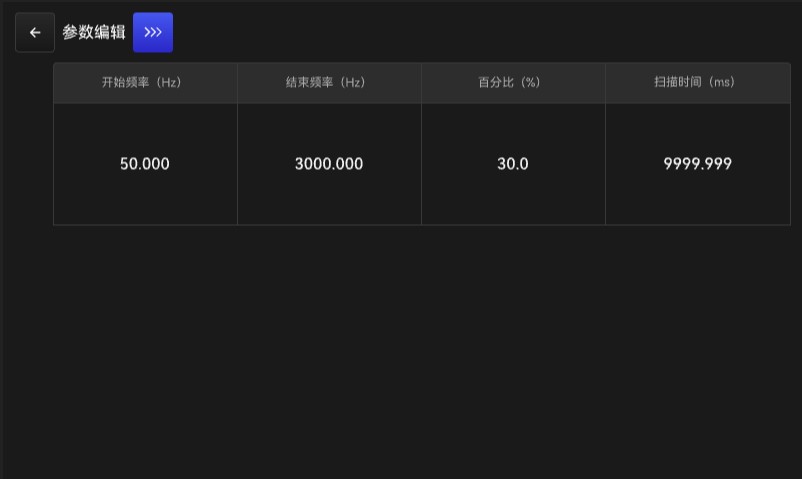
Figure 5.9.2 Editing Interharmonic Function Parameters
The Start/Stop button allows you to set both the start frequency and the stop frequency to the same value.
Click the “Edit Parameters >>>” button in Figure 5.9.2 to access the Interharmonic Parameter Settings—More Settings screen, as shown in Figure 5.9.3.

Figure 5.9.3 Additional Parameter Settings for Interharmonic Function Testing
2. Explanation of specific parameter options:
Start Frequency: The starting frequency of the swept wave superimposed on the fundamental wave, 0.1–3000.0 Hz;
End Frequency: The termination frequency of the swept wave superimposed on the fundamental frequency, 0.1–3000.0 Hz;
Percentage: The percentage of the harmonic relative to the fundamental voltage; range: MAX{start frequency, end frequency} ≤ 3000 Hz, harmonic content ≤ 30.0%;
Scan time: 10 ms–9999 s from the start frequency to the end frequency;
Unit: This option is used to configure the unit of measurement for the scan time, in ms/s;
5.9.3 Operational States of the Interharmonic Function
In the interharmonic function standby mode, tap the Start button in the upper-right corner of the screen to launch the interharmonic test function. The operating interface is shown in Figure 5.9.4.
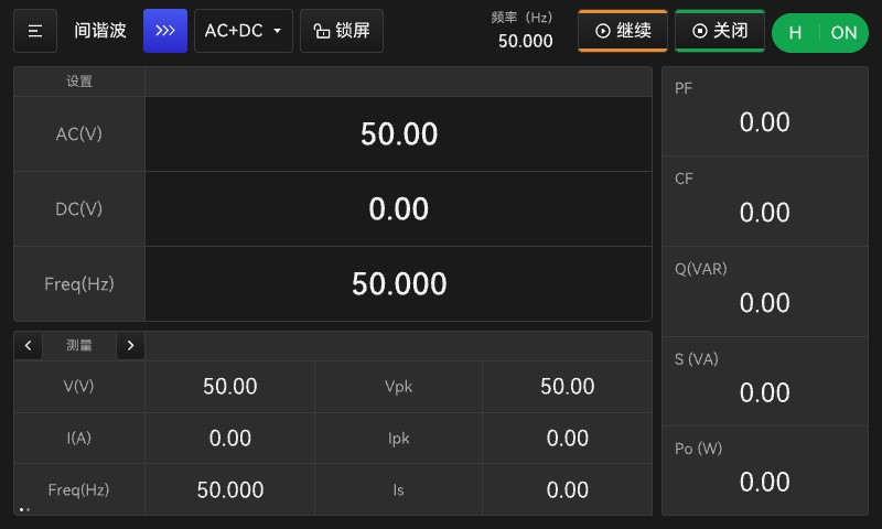
Figure 5.9.4: Interharmonic Test Function in Operation
This interface displays the operating frequency in real time, and the harmonic output function can be activated using the Pause/Resume buttons.
Once the interharmonic mode is activated, to turn off the output, press the Start button in the upper-right corner of the display, or use the ON/OFF button on the front panel. The measurement display area remains the same as in normal mode.
Note: The AC, DC, and Frwq parameters displayed on this screen are standard-mode parameters. Once the interharmonic mode is enabled, only the parameters set in the interharmonic mode parameter editor are output. The harmonic parameters are superimposed on the fundamental parameters.
Note: Interharmonic mode can only be activated using the “Start” button in the upper-right corner of the standby screen. To stop the mode, you can either use the “Stop” button in the upper-right corner or press the physical ON/OFF button on the front panel to turn off the output. If, in programming mode, you use the physical ON/OFF button on the front panel to turn on the power, the unit will operate in standard mode. At this point, you can tap the Start button on the display again to enter programming mode.

5.10 Harmonic Analysis Function (LSP-EMC Series Only)
5.10.1 Harmonic Analysis Function Standby Screen
This feature is only available when the device is in Normal (Manual) mode; it cannot be used in other operating modes.
From the mode selection screen, navigate to the harmonic analysis screen, then click >>> to enter parameter editing, as shown in Figure 5.10.1.
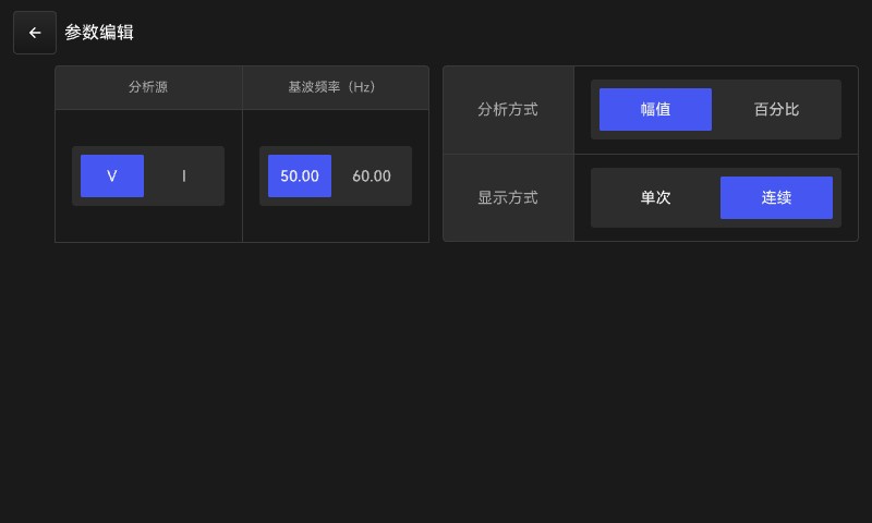
Figure 5.10.1 Harmonic Analysis Parameters Editor Interface
The harmonic analysis function allows users to measure total harmonic distortion (THD), DC component, fundamental component, and harmonic components up to the 40th order for 50 Hz or 60 Hz outputs. Note: When the output mode is DC or AC+DC and the AC voltage is 0 V, due to measurement errors and interference glitches, the measured distortion and harmonic content values may appear relatively high and fluctuate rapidly; this is normal behavior.
Meaning of specific parameter options:
Analysis Source: Select a measurement source—voltage U or current I
Fundamental Frequency: Measurable frequencies: 50 Hz or 60 Hz
Analysis Method: Calculated values for each harmonic: percentage or amplitude
Display Mode: Harmonic Measurement and Calculation Display Mode: Single calculation (recalculation can be triggered by pressing the Enter key) or continuous calculation of real-time harmonic content.
To use the harmonic analysis measurement function, press the ON/OFF button to activate the output while in normal (manual) standby mode or on the harmonic analysis screen (see Figure 5.10.2), and then click the Start button to display the harmonic content of the current voltage/current measurement, as shown in Figure 5.10.3.
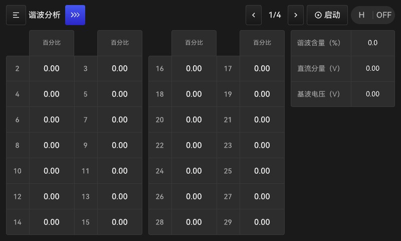
Figure 5.10.2 Percentage Analysis Mode Standby Screen
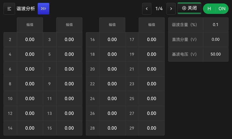
a. Amplitude Analysis Mode Startup Screen
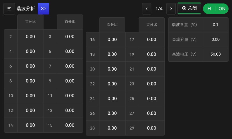
b. Percentage Analysis Mode Startup Screen
5.11 Alarm Screen
The AC test power supply provides comprehensive software and hardware protection. When a protection event is triggered, the power supply will stop outputting power and deactivate the output relay, while simultaneously entering the alarm screen to display the specific type of protection.
The AC test power supply provides comprehensive software and hardware protection. When a protection event is triggered, the power supply will stop outputting power and deactivate the output relay, while simultaneously entering the alarm interface to display the specific type of protection. Alarms are categorized as software alarms and hardware alarms, as shown in Figure 5.11.1.
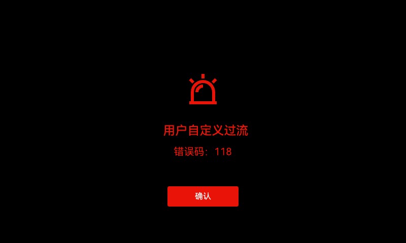
a Software Alert
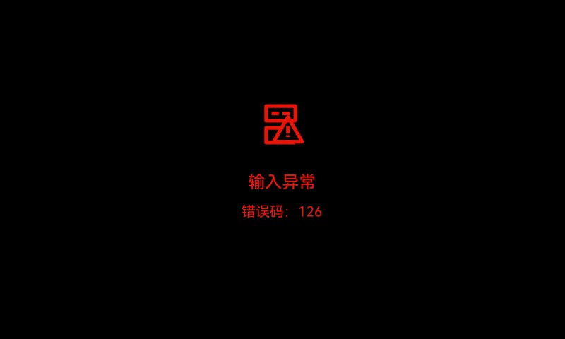
b Hardware Alarms
Figure 5.11.1 Alarm Screen
To return to normal standby mode, first remove the load and determine the cause of the protection event based on the protection type indicated. For software alarms, the alarm screen displays an “Acknowledge” option; clicking it clears the alarm. For hardware alarms, you must restart the power supply to clear the alarm.
Table 5.11.1 List of Alarm Codes
| Error Codes | Protection Type | Explanation of the Reason |
| 126 | Input Error | The input voltage does not meet the specified value. |
| 120 | Fan Malfunction | Fan Stopped Spinning |
| 121 | Output Short Circuit | Output Load Short Circuit |
| 122 | Overheating Error | Internal temperature is too high |
| 123 | ACDC Error | Internal AC-DC Power Module Malfunction |
| 124 | DCDC Anomaly | Internal DC-DC Power Module Malfunction |
| 116 | Overcurrent Protection | Output current exceeds the specified limit |
| 117 | Over-Power Protection | Output power exceeds the specified limit |
| 119 | User-Defined Overloads | The output current exceeds the set power limit. |
| 114 | Output Overvoltage | The output voltage exceeds the power supply’s safety threshold. The power supply output exceeds the set voltage by a significant margin. |
| 102 | AC Overvoltage Setting | The set voltage exceeds the AC range limit |
| 103 | DC Overvoltage Setting | The set voltage exceeds the limit for the DC range |
| 118 | User-Defined Overcurrent | The output current exceeds the set current limit (in both manual and automatic modes) |
| 125 | Self-Check Error | No 200V internal output was detected during the self-test. |
| 127 | EVH Alert | |
| Error Codes | Protection Type | Explanation of the Reason |
| E01 | Input Error | The input voltage does not meet the specified value. |
| E02 | Fan Malfunction | Fan Stopped Spinning |
| E03 | Output Short Circuit | Output Load Short Circuit |
| E04 | Overheating Error | Internal temperature is too high |
| E05 | ACDC Error | Internal AC-DC Power Module Malfunction |
| E06 | DCDC Anomaly | Internal DC-DC Power Module Malfunction |
| E07 | Overcurrent Protection | Output current exceeds the specified limit |
| E09 | Over-Power Protection | Output power exceeds the specified limit |
| E10 | Output Overvoltage | The output voltage exceeds the power supply’s safety threshold. The power supply output exceeds the set voltage by a significant margin (possibly overvoltage or undervoltage). |
| E13 | Set Overvoltage | Output voltage exceeds the range limit |
| E14 | User-Defined Overcurrent | The output current exceeds the set current limit (in both manual and automatic modes) |
6. External Interfaces
6.1 Communication Interfaces
Upon receiving the correct communication command, the power supply automatically returns to the standby screen, as shown in the figure below:
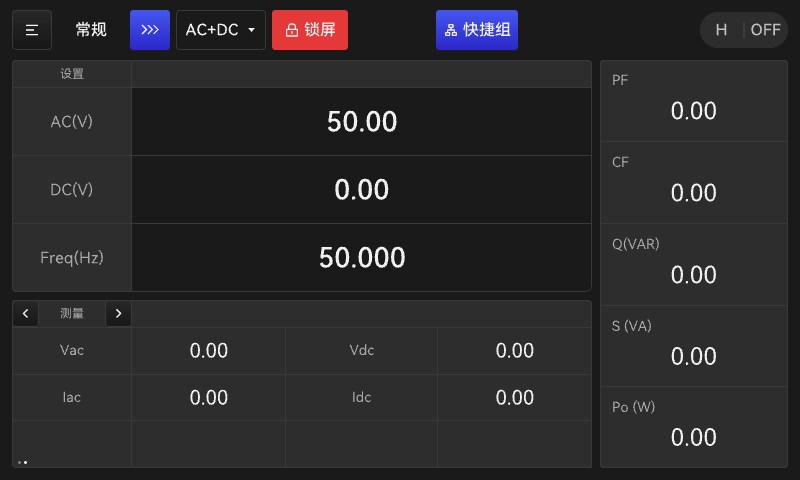
Figure 6.1.1 Standby Screen During Communication
In remote communication control mode, the lock button on the display lights up, indicating that the device is in communication control mode. Refer to the appendix for the specific communication command protocol.
6.1.1 RS-232 Interface (Standard)
You can configure the communication baud rate and communication address in the system settings. The device uses a 9-pin serial port; see below for specific connection instructions.
| Pin Numbers | Note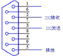 |
| 1 | NC (Not Connected) |
| 2 | RX (Receive) |
| 3 | TX (Send) |
| 4 | NC |
| 5 | GND (Ground) |
| 6 | NC |
| 7 | NC |
| 8 | NC |
| 9 | NC |
Figure 6.1.2 RS-232 Interface
6.1.2 RS-485 Interface (Optional)
When the RS-485 interface is selected as the communication port, the wiring is as shown in the figure below:
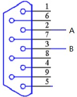
| Pin Numbers | Note |
| 1 | NC (Not Connected) |
| 2 | A |
| 3 | B |
| 4 | NC |
| 5 | GND (Ground) |
| 6 | NC |
| 7 | NC |
| 8 | NC |
| 9 | NC |
Figure 6.13 RS-485 Interface
Note: When 485 communication is selected, 232 communication is not available;
6.1.3 GPIB Interface (Optional)
When GPIB is selected as the communication port, the system settings screen appears as follows:
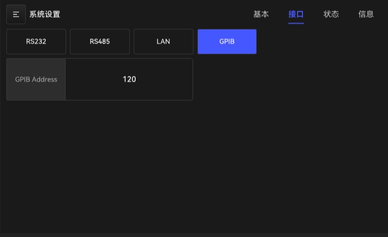
Figure 6.3 GPIB Interface Settings Screen
The GPIB address can be set within the range of 1 to 30. To change it, use the buttons or the knob; the setting will be automatically saved when you return.
Note: When GPIB communication is selected, RS-232/RS-485 communication is not available;
6.1.4 LAN Port (Optional)
When the LAN port is selected as the communication port, the last page of the system settings interface appears as follows:
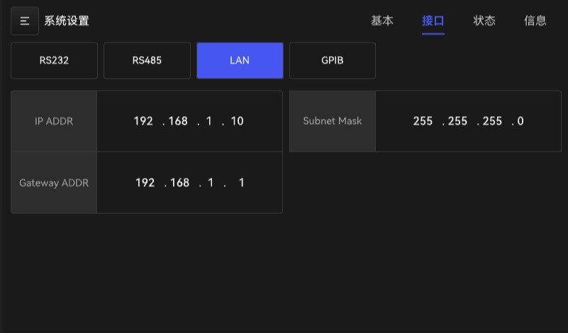
Figure 6.4 Ethernet Port Settings Screen
The default network settings are shown in the figure. To change them, use the buttons or the dial, and press SAVE to save your changes.
Note: When LAN communication is selected, 232/485 communication is not available;
6.2 Analog Control Interface
9-pin connector; see the table below for specific pin assignments.
| Pin Numbers | Note | Pin Numbers | Note |
| 1 | GND | 6 | GND |
| 2 | REMOTE | 7 | GND |
| 3 | GND | 8 | FAULT |
| 4 | ACON | 9 | NC |
| 5 | NC |
1, 3, 6, 7—GND;
2—-REMOTE: When this pin receives a low signal, the power supply shuts off. For detailed instructions, refer to the “Remote Control” option in the system settings;
4—-ACON Synchronization Signal: When the power supply begins outputting, this pin is set to a high level;
8—-FAULT Protection Control: High in normal operation; set to low during protection;
5, 9—-NC floating;
7. Maintenance and Quality Assurance
7.1 Maintenance Guide
To ensure the power supply operates stably over the long term, please follow these usage guidelines as closely as possible:
1. Keep the area clean and dry.
2. Periodically check that all functions of the power supply, as well as all buttons and knobs, are working properly.
3. Periodically inspect the input and output cables and terminal blocks for damage to the insulation; if any damage is found, replace them promptly.
4. Do not place heavy objects, tools, or other items on top of the power cord or the power supply cover, as this may damage the power cord’s insulation, expose the wires, and cause an electrical hazard that could result in injury. Also, do not place the power cord in areas with heavy foot traffic to avoid creating a hazard.
5. Do not pile up clutter around the power supply to avoid blocking its ventilation openings. Ensure proper airflow while the power supply is in operation.
6. Make sure the output current does not exceed the maximum output current or cause the unit to operate under overload conditions.
7. Stop the output before turning off the power.
8. Non-professionals should not turn on the power themselves to avoid injury or damage to the equipment.
7.2 Troubleshooting and Repair
See Table 7.1 for common problems and their solutions.
Table 7.1 Common Problems and Solutions
| Fault Symptoms | Possible Causes of Malfunction | Solution |
| No display after powering on | 1) Not plugged in 2) Abnormal power supply voltage | 1) Check that the power cord is connected properly. 2) Check that the instrument’s power supply voltage is normal. |
| Overvoltage Setpoint, Output Overvoltage | 1) The peak output voltage exceeds the specified limit. 2) The output sampling terminal on the rear panel is open-circuited. | 1) Check the set values for Va and Vd. 2) Ensure that the LS and NS measurement terminals are securely connected. |
| Overcurrent Protection: User-Defined Overcurrent | 1) The output current exceeds the specified limit. 2) The output current exceeds the current limit set by the user. | 1) Reduce the load 2) Relax the current limit |
| Output Short Circuit | 1) Excessive load inrush current (e.g., starting an inductive load) 2) Short circuit at the output | 1) Reduce the load (for example, by switching loads on and off in batches) or increase the power supply capacity. 2) Check for short-circuit faults and correct them. |
| Over-Power Protection | Output power exceeds the specified limit | 1) Reduce the load 2) Lower the output voltage |
| After startup, the voltage won’t rise. | 1) The rise time is too long. 2) The screw on the rear panel output measurement sampling port is not tightened. | 1) Check the rise time setting. 2) Securely connect the LS and NS measurement terminals. Note: The output voltage may be very high at this time. Do not touch any live parts at the rear to avoid injury. |
| Fan Malfunction | 1) The fan wires are broken or the connections are loose. 2) Excessive dust inside the chassis has caused the fan to stop running. | 1) Call customer service for repair assistance. 2) Remove dust from inside the case. |
| Overheating Error | 1) The ambient temperature is too high. 2) The vents are blocked. | 1) The machine’s operating temperature range is 0–40°C. 2) Clear the ventilation openings. |
| Input Error | Input voltage is higher or lower than specified | Check whether the input voltage exceeds the specified range |
| ACDC Error | 1) Periodic loss of input voltage 2) Momentary overcurrent in the output 3) Internal module failure | 1) Check the stability of the input voltage. 2) Remove the load. 3) Call customer service for repair assistance. |
| DCDC Anomaly | 1) Periodic loss of input voltage 2) Momentary overcurrent in the output 3) Internal module failure | 1) Check the stability of the input voltage. 2) Remove the load. 3) Call customer service for assistance with repairs. |
8. Communication Protocols
Note: When using this device to communicate with a PC, you must ensure that:

1. The RS232/RS485 address settings on this unit must match the address selected on the host computer!
2. The RS232/RS485 baud rate setting on this device must match the baud rate selected on the host computer!
3. The host computer must send commands in accordance with the “Command Data Format for Download”! This device supports two communication standards: LSP 3.0 and SCPI. Please select one of them and configure the corresponding communication protocol option in the device’s system settings accordingly.
Otherwise, communication will not be possible!
I.1 Hardware Interface Standards
1. Configured as an RS-232 interface and compliant with the RS-232 communication standard.
2. When the device uses an RS232/RS485 interface, the communication baud rate can be manually set to 1200, 9600, 19200, or 38400; the default setting is 38400.
3. The data frame format consists of 1 start bit, 8 data bits, and 1 stop bit, for a total of 10 bits.
I.2 LSP 3.0 Communication Protocol
I.2.1 LSP 3.0 Communication Standard
1. The device address can be set manually to any value between 1 and 255.
2. Communication for this measuring instrument is divided into two categories: receiving information and sending information. The standardized format for this information is as follows:
| Frame Header | Total number of bytes | Start Address | Command | Command | Command | Checksum | End of Frame |
| Frame Header | Total number of bytes | Start Address | Types | Command Word | Parameters | Checksum | End of Frame |
| 0x7B | XX | X | X | X | XXXXX | X | 0x7D |
Header: 1 byte, fixed at 0x7B, which is the ASCII code for ‘{’.
Total number of bytes: 2 bytes. The value is the sum of the frame header, total number of bytes, slave address, command type, command word, command parameters, checksum, and the number of bytes in the frame trailer, with the high byte first and the low byte last.
Address: 1 byte; this is the local communication address. 0x00 is a special address code used for broadcasting, but it can only execute control, configuration, and debugging commands (excluding queries) and does not send a response.
Commands: The length in bytes varies; see “Communication Command Descriptions” for the length of each command.
Checksum: 1 byte (hexadecimal); this is the result of verifying the transmitted data. A horizontal checksum is used, calculated as the sum of the number of bytes, the slave address, and the command, with the least significant byte serving as the checksum.
Frame End: 1 byte, fixed at 0x7D, which is the ASCII code for ‘}’.
Data Format: All data is in hexadecimal format, with the most significant bit first and the least significant bit last. For example, for 2-byte data: 300.0 V with a unit of 0.1 V is actually 3000 (the value divided by the smallest unit), which is 0BB8 in hexadecimal; -424.2 V with a unit of 0.1 V is actually -4242, which is EF6E in hexadecimal.
I.2.2 List of LSP 3.0 Communication Commands
| Command Class | Instruction Code | Command Word | Function Description |
| Control Class | 0x0F | 0x00 | Stop |
| Control Class | 0x0F | 0xFF | Start |
| Control Class | 0x0F | 0x01 | Stop Triggering |
| Control Class | 0x0F | 0xFE | Trigger |
| Control Class | 0x0F | 0x02 | Pause |
| Control Class | 0x0F | 0x0B | Continue |
| Configuration Class | 0x5A | 0x15 | General Settings |
| Configuration Class | 0x5A | 0x16 | Set Sequence Mode |
| Configuration Class | 0x5A | 0x17 | Set Pulse Mode |
| Configuration Class | 0x5A | 0x18 | Set Harmonic Mode |
| Configuration Class | 0x5A | 0x19 | Set Interharmonic Mode |
| Configuration Class | 0x5A | 0x1A | Set the Stepping Mode |
| Configuration Class | 0x5A | 0x1B | Set the Harmonic Measurement Mode |
| Configuration Class | 0x5A | 0x20 | Set Output Mode |
| Configuration Class | 0x5A | 0x41 | Set General Parameters |
| Configuration Class | 0x5A | 0x40 | Set General and Additional Parameters |
| Configuration Class | 0x5A | 0x51 | Set Sequence Parameters |
| Configuration Class | 0x5A | 0x29 | Set additional parameters for the sequence |
| Configuration Class | 0x5A | 0x2B | Set Pulse Parameters |
| Configuration Class | 0x5A | 0x2A | Set Additional Pulse Parameters |
| Configuration Class | 0x5A | 0x2D | Set Stepper Parameters |
| Configuration Class | 0x5A | 0x2C | Set Additional Parameters for Stepping |
| Configuration Class | 0x5A | 0x61 | Set Up Harmonic Groups |
| Configuration Class | 0x5A | 0x62 | Set Harmonic Parameters |
| Configuration Class | 0x5A | 0x64 | Set Additional Harmonic Parameters |
| Configuration Class | 0x5A | 0x32 | Set Interharmonic Parameters |
| Configuration Class | 0x5A | 0x70 | Set Harmonic Measurement Parameters |
| Configuration Class | 0x5A | 0x80 | Output Limit Parameter Settings |
| Configuration Class | 0x5A | 0x81 | Output Protection Parameter Settings |
| Configuration Class | 0x5A | 0x82 | Output Waveform Parameter Settings |
| Configuration Class | 0x5A | 0x83 | Output Other Parameter Settings |
| Configuration Class | 0x5A | 0x90 | System Status Settings |
| Query Settings Class | 0xA5 | 0x20 | Query Output Format |
| Query Settings Class | 0xA5 | 0x41 | Query General Parameters |
| Query Settings Class | 0xA5 | 0x40 | View More General Parameters |
| Query Settings Class | 0xA5 | 0x51 | Query Sequence Parameters |
| Query Settings Class | 0xA5 | 0x29 | More Parameters for Query Sequences |
| Query Settings Class | 0xA5 | 0x2B | Query Pulse Parameters |
| Query Settings Class | 0xA5 | 0x2A | View more parameters for the pulse |
| Query Settings Class | 0xA5 | 0x2D | Query Stepper Parameters |
| Query Settings Class | 0xA5 | 0x2C | Look up more parameters for the stepper |
| Query Settings Class | 0xA5 | 0x61 | Query Harmonic Synthesis Methods |
| Query Settings Class | 0xA5 | 0x62 | Query Harmonic Parameters |
| Query Settings Class | 0xA5 | 0x64 | View More Parameters for Harmonics |
| Query Settings Class | 0xA5 | 0x32 | Query Interharmonic Parameters |
| Query Settings Class | 0xA5 | 0x70 | Query Harmonic Measurement Parameters |
| Query Settings Class | 0xA5 | 0x80 | Query Output Limit Parameters |
| Query Settings Class | 0xA5 | 0x81 | Query Output Protection Parameters |
| Query Settings Class | 0xA5 | 0x82 | Query Output Waveform Parameters |
| Query Settings Class | 0xA5 | 0x83 | Query Output: Other Parameters |
| Query Settings Class | 0xA5 | 0x90 | Query System Status Parameters |
Note: There are no corresponding communication commands for harmonic synthesis, harmonic analysis, or interharmonic functions in 618.
I.2.3 Detailed Explanation of LSP 3.0 Communication Commands
I.2.3.1 Control Commands (0x0F)
Command word: 00H
Command function: Stop output/Stop test
Command format: 0x7B XX X 0x0F 0x00 X 0x7D (8 bytes)
Example command: 7B 00 08 01 0F 00 18 7D
Command word: FFH
Command Function: Start Output / Start Test
Command format: 0x7B XX X 0x0F 0xFF X 0x7D (8 bytes)
Example command: 7B 00 08 01 0F FF 17 7D
Command word: 01H
Command Function: Stop Triggering
Command format: 0x7B XX X 0x0F 0x01 X 0x7D (8 bytes)
Example command: 7B 00 08 01 0F 01 19 7D
Command code: FEH
Command Function: Trigger
Command format: 0x7B XX X 0x0F 0xFE X 0x7D (8 bytes)
Example command: 7B 00 08 01 0F FE 16 7D
Command code: 03H
Command Function: Clear Alarm
Command format: 0x7B XX X 0x0F 0x03 X 0x7D (8 bytes)
Example command: 7B 00 08 01 0F 03 1B 7D
Command word: 02H
Command Function: Pause
Command format: 0x7B XX X 0x0F 0x02 X 0x7D (8 bytes)
Example command: 7B 00 08 01 0F 02 1A 7D
Command word: FDH
Command function: Continue
Command format: 0x7B XX X 0x0F 0xFD X 0x7D (8 bytes)
Example command: 7B 00 08 01 0F FD 15 7D
I.2.3.2 Query Commands (0xF0)
Command word: EBH
Command Function: Query instrument status/alarm codes
Command format: 0x7B XX X 0xF0 0xEB X 0x7D (8 bytes)
Example command: 7B 00 08 01 F0 EB E4 7D
Response format: 0x7B XX X 0xF0 0xEB X XX (1-byte status + 2-byte data) X 0x7D (11 bytes)
Command: EDH
Command Function: Query instrument model
Command format: 0x7B XX X 0xF0 0xED X 0x7D (8 bytes)
Example command: 7B 00 08 01 F0 ED E6 7D
Response Format: 0x7B XX X 0xF0 0xED XXXXXXXXXXXXXXXX (16-byte ASCII code, such as “ANRGS015AG”) X 0x7D (24 bytes)
Command code: A4H
Command Function: Queries and outputs measurement values: voltage, current, frequency, power, crest factor, peak current, etc. If the device is not in the active state, it returns all zeros.
Command format: 0x7B XX X 0xF0 0xA4 X 0x7D (8 bytes)
Example command: 7B 00 08 01 F0 A4 9D 7D
Response Format: 0x7B XX X 0xF0 0xA4 XX XX XXXX XXX XX XXX XX XX XXX XXX XX XX XX XX XX XX (2-byte mixed voltage unit: 0.01 V;2-byte hybrid current unit: 0.1 A; 1-byte active power sign bit, 3-byte active power unit: 0.01 W; 3-byte apparent power unit: 0.01 VA; 2-byte power factor unit: 0.01%;3-byte frequency unit: 0.001 Hz; 2-byte AC voltage unit: 0.01 V; 2-byte AC current unit: 0.01 A; 3-byte reactive power unit: 0.01 W;3-byte DC voltage, unit 0.01 V; 2-byte DC current, unit 0.01 A; 2-byte peak factor, unit 0.01%; 2-byte peak voltage, unit 0.01 V;2-byte peak current, unit 0.01 A; 2-byte surge current, unit 0.01 A; 2-byte line voltage, unit 0.01 V (the next two blocks are identical) XXX XX XXX XXX XXX XX XX XX XXX XX XXX XXX XXX XX XX XX 0x7D (122 bytes)
Command Word: 71H
Command Function: Retrieves harmonic measurement values: voltage, current, frequency, power, crest factor, peak current, etc. If the system is not in the active state, all values returned are 0.
Command format: 0x7B XX X 0xF0 0x71 X 0x7D (8 bytes)
Example command: 7B 00 08 01 F0 71 6A 7D
Response Format: 0x7B XX X F0 71 XX……XX XX XXX XX X 7D
Data Code Explanation:
| XX……XX | Harmonics 1–40, two bytes per harmonic |
| XX | Harmonic Content |
| XXX | DC component (three bytes) |
| XX | Fundamental Frequency |
I.2.3.3 Configuration Commands (0x5A)
Command Word: 16H
Command Function: Sets the mode to “Sequence”; valid only when not in the “Execute,” “Alarm,” or “Emergency Stop” states.
Command format: 0x7B XX X 0x5A 0x16 X 0x7D (8 bytes)
Example command: 7B 00 08 01 5A 16 79 7D
Command Word: 17H
Command Function: Sets the mode to pulse; valid only when not in run, alarm, or emergency stop mode.
Command format: 0x7B XX X 0x5A 0x17 X 0x7D (8 bytes)
Example command: 7B 00 08 01 5A 17 7A 7D
Command Word: 18H
Command Function: Sets the mode to “Harmonic”; effective only when not in the “Execute,” “Alarm,” or “Emergency Stop” states.
Command format: 0x7B XX X 0x5A 0x18 X 0x7D (8 bytes)
Example command: 7B 00 08 01 5A 18 7B 7D
Command Word: 19H
Command Function: Sets the mode to interharmonic; valid only in non-execution, alarm, or emergency stop states.
Command format: 0x7B XX X 0x5A 0x19 X 0x7D (8 bytes)
Example command: 7B 00 08 01 5A 19 7C 7D
Command word: 1AH
Command Function: Sets the mode to step mode; valid only when not in execution, alarm, or emergency stop states.
Command format: 0x7B XX X 0x5A 0x1A X 0x7D (8 bytes)
Example command: 7B 00 08 01 5A 1A 7D 7D
Command word: 1BH
Command Function: Sets the mode to harmonic measurement
Command format: 0x7B XX X 0x5A 0x1B X 0x7D (18 bytes)
Example command: 7B 00 08 01 5A 1B 7E 7D
Command word: 20H
Command Function: Sets the output mode; valid only in non-execution, alarm, or emergency stop states.
Command format: 0x7B XX X 0x5A 0x20 X (1-byte output mode) X 0x7D (9 bytes)
Command example: 7B 00 09 01 5A 20 01 85 7D (Set the output mode to AC)
Command word: 41H
Command Function: General Parameter Settings
Command format: 0x7B XX X 0x5A 0x41 XX (2 bytes, AC voltage 0.00–300 V) XXX (3 bytes, DC voltage -424.2–424.2) XXX (3 bytes, frequency 30–100 Hz) X 0x7D (16 bytes)
Command Examples:7B 00 10 01 5A 41 55F0 000000 00C350 04 7D (Set AC voltage to 220.00 V, DC voltage to 0.00 V, and frequency to 50.000 Hz)
Command word: 40H
Command Function: General Additional Parameter Settings
Command format: 0x7B XX X 0x5A 0x40 XX (2-byte start angle 0–359.9°, unit 0.1°) XX (2-byte stop angle 0–359.9°, unit: 0.1°) XXX (3-byte AC conversion rate: 0.00–2000.00 V, unit: 0.01 V/ms) XXX (3-byte DC conversion rate: 0.00–2000.00 V, unit 0.01 V/ms) XXX (3-byte frequency conversion rate 0.000–200.000 Hz, unit 0.001 Hz/ms) XXX (3-byte end DC conversion rate 0.00–2000.00 V, unit 0.01 V/ms) X (1-byte waveform selection 0–7) X (1-byte mode selection; effective only when the waveform is set to clamped sine wave: 0: AMP;1: THD) XX (2 bytes—percentage; effective only when the waveform selection is a clamped sine wave: AMP 0.0–100.0, THD 0.0–43.0) X (1-byte waveform group number; applies only when the waveform selection is a built-in or custom waveform: 1–30) X 0x7D (29 bytes)
Command Examples:7B 00 1D 01 5A 40 0384 0A8C 000064 0003E8 0186A0 0186A0 00 00 00 00 00 72 7D (Set start angle to 90.0°, end angle to 270.0°, AC slew rate to 1.00 V/ms, DC slew rate to 10.00 V/ms, frequency conversion rate 100.000 Hz/ms, end DC conversion rate 1000.00 V/ms, waveform selection 0, mode 0, percentage 0, waveform group number 0)
Command word: 51H
Command Function: Sequence Parameter Settings
Command format: 0x7B XX X 0x5A 0x51 X (1-byte step number) XX (2-byte AC start voltage 0.00–300.00 V, unit 0.01 V) XX (2-byte AC end voltage 0.00–300.00 V, unit 0.01 V) XXX (3-byte DC start voltage –424.20–424.20 V, unit 0.01 V) XXX (3-byte DC end voltage -424.20 to 424.20 V, unit 0.01 V) XXX (3-byte frequency start 15.000–200.000 Hz, unit 0.001 Hz) XXX (3-byte frequency end 15.000–200.000 Hz, unit 0.001 Hz) X (1-byte waveform selection 0–7) X (1-byte waveform group number; applies only when waveform selection is set to built-in or custom waveforms, 1–30) XX (2-byte step phase 0.0–360.0°, unit: 0.1°) XXX (3-byte run length: 0.0–99999, unit: ms) X 0x7D (32 bytes)
Command Examples:7B 00 20 01 5A 51 01 01F4 00C8 000000 000000 00C350 00C350 02 00 0000 000064 16 7D (Sets the AC start voltage to 5.00 V, the AC end voltage to 2.00 V, both DC start and end voltages to 0.00 V, the start frequency to 50.000 Hz, and the end frequency to 50.000 Hz; waveform selection number 2 (sinusoidal wave), waveform group number is invalid, start angle 0.0 degrees, runtime 100 ms)
Command word: 29H
Command Function: Additional Parameter Settings for the Sequence
Command Format: 0x7B XX X 0x5A 0x29 X (1-byte trigger mode: 0: Automatic, 1: Manual) X (1-byte unit of measurement: 0: Time, 1: Count) X (1-byte stage continuation: 0: Disabled, 1: Enabled) XX (2-byte number of runs) X 0x7D (13 bytes)
Command example: 7B 00 0D 01 5A 29 00 00 00 0009 9A 7D (Set trigger mode to automatic, duration to unit time, phase continuation disabled, and number of runs to 9)
Instruction code: 2BH
Command Function: Pulse Parameter Settings
Command format: 0x7B XX X 0x5A 0x2B XX (2-byte AC voltage 0.00–300.00 V, in 0.01 V increments) XXX (3-byte DC voltage -424.20–424.20 V, unit: 0.01 V) XXX (3-byte frequency: 15.000–200.000 Hz, unit: 0.001 Hz) XX (2-byte start angle: 0.0–360.0°, unit 0.1°) XX (2-byte duty cycle 0.0–100.0%, unit 0.1%) X (1-byte waveform selection 0–7) X (1-byte waveform group number; applies only when waveform selection is set to built-in or custom waveforms, 1–30) XXX (3-byte run length 0.0–99999, unit: ms) X 0x7D(25 bytes)
Command Example: 7B 00 19 01 5A 2B 55F0 0055F0 00C350 0000 0000 00 00 0003E8 27 7D (Set AC voltage to 220.00 V, DC voltage to 220.00 V, frequency to 50.000 Hz, start angle to 0.0°, duty cycle to 0.0%, waveform selection to 0, waveform group number to 0, and period to 1000 ms)
Command word: 2AH
Command Function: Additional Pulse Parameter Settings
Command format: 0x7B XX X 0x5A 0x2A X (1-byte trigger mode: 0 = Automatic, 1 = Manual) XX (2-byte number of runs) X 0x7D (11 bytes)
Command example: 7B 00 0B 01 5A 2A 00 0001 91 7D (Set the trigger mode to “Automatic” and the number of runs to 1)
Command word: 2DH
Command Function: Stepper Parameter Settings
Command format: 0x7B XX X 0x5A 0x2D XX (2-byte AC voltage 0.00–300.00 V, in 0.01 V increments) XX (2-byte AC difference 0.00–300.00 V, unit: 0.01 V) XXX (3-byte DC voltage: -424.20 to 424.20 V, unit: 0.01 V) XXX (3-byte DC difference: -424.20 to 424.20 V, unit 0.01 V) XXX (3-byte frequency 15.000–200.000 Hz, unit 0.001 Hz) XXX (3-byte frequency difference 15.000–200.000 Hz, unit 0.001 Hz) XX (2-byte start angle 0.0–360.0°, unit 0.1°) X (1-byte waveform selection 0–7) X (1-byte waveform group number; applies only when waveform selection is set to built-in or custom waveforms, 1–30) XX (2-byte number of runs: 0–999) XXX (3-byte step time: 0.0–99999, unit: ms) X 0x7D (33 bytes)
Command Examples:7B 00 21 01 5A 2D 0000 00C8 000000 000000 00C350 000000 0000 02 00 0002 000064 EC 7D (Set AC start voltage to 0.00 V, AC voltage difference to 2.00 V, DC start voltage to 0.00 V, DC voltage difference to 0.00 V, start frequency to 50.000 Hz, frequency difference 0.000 Hz, waveform selection number 2 (i.e., sine wave), waveform selection group number 0, number of runs 2, run time 100 ms)
Command code: 2CH
Command Function: Additional Parameter Settings for Stepping
Command format: 0x7B XX X 0x5A 0x2C X (1-byte trigger mode: 0 = Automatic, 1 = Manual) X 0x7D (9 bytes)
Command example: 7B 00 09 01 5A 2C 00 90 7D (Set trigger mode to automatic)
Command word: 61H
Command Function: Sets the harmonic synthesis mode
Command format: 0x7B XX X 0x5A 0x61 X (1-byte composition method) X 0x7D (9 bytes)
Command example: 7B 00 09 01 5A 61 01 C6 7D (Set the blending mode to 0)
Command word: 64H
Command Function: Harmonic Parameter Settings
Command format: 0x7B XX X 0x5A 64 X (1-byte group number) X (1-byte step number) XX (2-byte amplitude/percentage: 2–10 times 0–90.0 V/30.0%; Cycles 11–20: 60.0 V/30.0%; Cycles 21–40: 30.0 V/30.0%;41–50: 15.0 V / 30.0%, in increments of 0.1 V / 0.1%); XX (2-byte angle, 0.0–360.0°, in increments of 0.1°) X 0x7D (14 bytes)
Command example: 7B 00 0E 01 5A 64 00 02 01 2C 03 84 83 7D (Set group number to 0, step number to 2, amplitude to 30.0 V, and angle to 90.0°)
Command word: 62H
Command Function: Additional Harmonic Parameter Settings
Command format: 0x7B XX X 0x5A 0x62 XX (2-byte fundamental voltage 0.00–300.00 V, unit: 0.01 V) XXX (3-byte fundamental frequency 15.000–200.000 Hz, unit: 0.001 Hz) XXX (3-byte DC component –424.20–424.20 V, unit: 0.01 V) XX (2-byte start angle: 0.0–360.0°, unit: 0.1°) X 0x7D (18 bytes)
Command example: 7B 00 12 01 5A 62 55 F0 00 C3 50 00 03 E8 03 84 99 7D (Set fundamental voltage to 220.00 V, frequency 50.000 Hz, DC component 10.00 V, and starting angle 90.0°)
Command word: 32H
Command Function: Interharmonic Parameter Settings
Command format: 0x7B XX X 0x5A 0x32 XXX (3-byte start frequency 15.000–3000.000 Hz, unit 0.001 Hz) XXX (3-byte end frequency: 15.000–3000.000 Hz, unit: 0.001 Hz) XX (2-byte percentage: 0.00–30.00, unit: 0.01%) XXX (3-byte scan time 0.0–99999, unit: ms) X 0x7D (19 bytes)
Command Examples:7B 00 13 01 5A 60 00 EA 60 2D C6 C0 0B B8 00 03 E8 79 7D (Set start frequency to 60.000 Hz, end frequency to 3000.000 Hz, a percentage of 30.00%, and a scan time of 1000 ms)
Command Word: 70H
Command Function: Harmonic Analysis Parameter Settings
Command Format: 0x7B XX X 0x5A 0x70 X (1-byte analysis source 0: voltage; 1: current) X (1-byte fundamental frequency 0: 50.00 Hz;1: 60.00 Hz) X (1-byte analysis mode: 0: amplitude; 1: percentage) X (1-byte display mode: 0: single; 1: continuous) X 0x7D (12 bytes)
Command example: 7B 00 0C 01 5A 70 01 01 01 01 DB 7D (Set the analysis source to current, the fundamental frequency to 60.00 Hz, the analysis mode to Percentage 1, and the display mode to Continuous)
Command word: 80H
Command Function: Output limit parameter settings
Command format: 0x7B XX X 0x5A 0x80 XX (2-byte AC voltage limit: 0.00–300.00 V, in 0.01 V increments) XXX (3-byte DC voltage positive limit: 0.00–424.20 V, unit: 0.01 V) XXX (3-byte DC voltage positive limit: -424.20 to 0.00 V, unit: 0.01 V) XXX (3-byte frequency limit: 15.000–200.000 Hz, unit: 0.001 Hz) X 0x7D (19 bytes)
Command example: 7B 00 13 01 5A 80 75 30 00 A5 A0 00 00 00 03 0D 40 28 7D (Set the AC voltage limit to 300.00 V, positive DC voltage limit at 424.00 V, negative DC voltage limit at 0.00 V, and frequency limit at 200.000 Hz)
Command word: 81H
Command Function: Display protection parameter settings
Command Format: 0x7B XX X 0x5A 0x81 XX (1-byte overcurrent limit, 0–25 V, unit: A) X (1-byte overcurrent delay time, 0–9, in seconds) XXXX (2-byte overload limit, 0–5000 VA, in VA) X 0x7D (15 bytes)
Command example: 7B 00 0F 01 5A 81 0019 09 00001388 A8 7D (Sets the overcurrent limit to 0.25 A, the overcurrent delay time to 9 seconds, and the overload limit to 50.00 VA)
Command word: 82H
Command Function: Display waveform parameter settings
Command Format: 0x7B XX X 0x5A 0x82 X (Waveform A selection 0–5) X (Waveform B selection 0–5) X X (1 byte × 2: Mode selection; only applies when the waveform is set to clamped sine wave: 0: AMP;1: THD) XX XX (2 bytes × 2: Percentage; effective only when the waveform selection is a clamped sine wave—AMP 0.0–100.0, THD 0.0–43.0) X X (1 byte × 2: Waveform group number; effective only when the waveform is set to a built-in or custom waveform (1–30) X 0x7D (18 bytes)
Example command: 7B 00 12 01 5A 82 00 00 00 00 00 00 00 00 00 00 EF 7D
Command word: 83H
Command Function: Displays other parameter settings
Command Format: 0x7B XX X 0x5A 0x83 X (1-byte output relay: 0 = Off, 1 = On) X (Remote suppression: 0 = Off, 1 = On) X (Remote Control: 0 = Off, 1 = On) XX (Surge Duration in ms, 0–999) X (61 Voltage Levels: 0 = Low,1: High, 2: Auto) XX (Surge start time in ms, 0–999), X (External control switch: 0: Off, 1: On), X (External control mode: 0: Amplified, 1: Linear) X 0x7D (18 bytes)
Command Example: 7B 00 12 01 5A 83 01 00 00 0000 02 0000 00 00 F3 7D (Output relay ON, remote suppression OFF, remote control OFF, surge duration 0, voltage range automatic, surge start time 0, external control OFF, external control mode amplified)
Command Word: 90H
Command Function: Setting Virtual Impedance Parameters (61)
Command format: 0x7B XX X 0x5A 0x90 X (1-byte virtual impedance switch: 0 = Off, 1 = On) X (1-byte inductance value 0–100, representing 0.00–1.00 mH) X (1-byte resistance value 0–100, representing 0.00–1.00 ohms) X X (Unused) X 0x7D (13 bytes)
Command example: 7B 00 0D 01 5A 90 00 38 4e 00 00 7E 7D (virtual impedance off, inductance 0.56 mH, resistance 0.78 ohms)
I.2.3.4 Commands for Querying Settings (0xA5)
Command word: 41H
Command Function: Query General Parameter Settings
Command format: 0x7B XX X 0xA5 0x41 X 0x7D (8 bytes)
Example command: 7B 00 08 01 A5 41 EF 7D
Response Format: 0x7B XX X 0xA5 0x41 XX (2-byte AC voltage, in units of 0.01 V) XXX (3-byte DC voltage, in units of 0.01 V) XXX (3-byte frequency, in units of 0.001 Hz) X 0x7D(16 bytes)
Command word: 40H
Command Function: Query general and additional parameter settings
Command format: 0x7B XX X 0xA5 0x40 X 0x7D (8 bytes)
Example command: 7B 00 08 01 A5 40 EE 7D
Response Format: 0x7B XX X 0xA5 0x40 XX (2-byte start angle, unit: 0.1°) XX (2-byte stop angle, unit: 0.1°) XXX (3-byte AC conversion rate, unit: 0.01 V/ms) XXX (3-byte AC conversion rate, unit: 0.01 V/ms) XXX (3-byte frequency conversion rate, unit: 0.001 Hz/ms) XXX (3-byte DC conversion rate, unit: 0.01 V/ms) X (1-byte waveform selection) X (1-byte mode selection, 0: AMP; 1: THD) XX (2-byte percentage) X (1-byte waveform group number) X 0x7D (29 bytes)
Command word: 51H
Command Function: Query sequence parameter settings
Command format: 0x7B XX X 0xA5 0x51 X (1-byte step number) X 0x7D (9 bytes)
Example command: 7B 00 09 01 A5 51 00 00 7D
Response Format: 0x7B XX X 0xA5 0x51 X (1-byte step number) XX (2-byte AC start voltage, in units of 0.01 V) XX (2-byte AC end voltage, in units of 0.01 V) XXX (3-byte DC start voltage, in units of 0.01 V) XXX (3-byte DC end voltage, in units of 0.01 V) XXX (3-byte start frequency, in units of 0.001 Hz) XXX (3-byte end frequency, in units of 0.001 Hz) X (1-byte waveform selection) X (1-byte waveform group number) XX (2-byte step phase, unit: 0.1°) XXX (3-byte run length, unit: ms) X 0x7D (32 bytes)
Command word: 29H
Command Function: Query additional parameter settings for the sequence
Command format: 0x7B XX X 0xA5 0x29 X 0x7D (8 bytes)
Example command: 7B 00 08 01 A5 29 D7 7D
Response Format: 0x7B XX X 0xA5 0x29 X (1-byte trigger mode: 0: Automatic, 1: Manual) X (1-byte unit of measurement: 0: Time; 1: Count) X (1-byte phase continuation: 0: Disabled; 1: Enabled) XX (2-byte number of runs) X 0x7D (13 bytes)
Instruction code: 2BH
Command Function: Query pulse parameter settings
Command format: 0x7B XX X 0xA5 0x2B X 0x7D (8 bytes)
Example command: 7B 00 08 01 A5 2B D9 7D
Response Format: 0x7B XX X 0xA5 0x2B XX (2-byte AC voltage, unit: 0.01 V) XXX (3-byte DC voltage, unit: 0.01 V) XXX (3-byte frequency, unit: 0.001 Hz) XX (2-byte start angle, unit: 0.1°) XX (2-byte duty cycle, unit: 0.1%) X (1-byte waveform selection) X (1-byte waveform group number) XXX (3-byte run length, unit: ms) X 0x7D(32 bytes)
Command word: 2AH
Command Function: Query additional pulse parameter settings
Command format: 0x7B XX X 0xA5 0x2A X 0x7D (8 bytes)
Example command: 7B 00 08 01 A5 2A D8 7D
Response Format: 0x7B XX X 0xA5 0x31 X (1-byte trigger mode: 0 = Auto, 1 = Manual) XX (2-byte number of runs) X 0x7D (11 bytes)
Command word: 2DH
Command Function: Query stepper parameter settings
Command format: 0x7B XX X 0xA5 0x2D X 0x7D (8 bytes)
Example command: 7B 00 08 01 A5 2D DB 7D
Response Format: 0x7B XX X 0xA5 0x2D XX (2-byte AC voltage, unit: 0.01 V) XX (2-byte AC difference, unit: 0.01 V) XXX (3-byte DC voltage, unit: 0.01 V) XXX (3-byte DC difference, unit: 0.01 V) XXX (3-byte frequency, unit: 0.001 Hz) XXX (3-byte frequency difference, unit: 0.001 Hz) XX (2-byte start angle, unit: 0.1°) X (1-byte waveform selection) X (1-byte waveform group number) XX (2-byte number of runs) XXX (3-byte step time, unit: ms) X 0x7D (33 bytes)
Command code: 2CH
Command Function: Query additional parameter settings for the stepper
Command format: 0x7B XX X 0xA5 0x2C X 0x7D (8 bytes)
Example command: 7B 00 08 01 A5 2C DA 7D
Response Format: 0x7B XX X 0xA5 0x2C X (1-byte trigger mode: 0 = Automatic, 1 = Manual) XX (2-byte number of runs) X 0x7D (11 bytes)
Command word: 61H
Command Function: Query harmonic synthesis method
Command format: 0x7B XX X 0xA5 0x61 X 0x7D (8 bytes)
Example command: 7B 00 08 01 A5 61 0F 7D
Response Format: 0x7B XX X 0xA5 0x61 X (1-byte concatenation) X 0x7D (9 bytes)
Command word: 64H
Command Function: Query harmonic parameter settings
Command format: 0x7B XX X 0xA5 0x64 X 0x7D (10 bytes)
Example command: 7B 00 0A 01 A5 64 01 00 15 7D
Response Format: 0x7B XX X 0xA5 0x64 X (1-byte group number) X (1-byte step number) XX (2-byte amplitude/percentage unit 0.1V/0.1%) XX (2-byte angle, unit 0.1°) X 0x7D (14 bytes)
Command word: 62H
Command Function: Query additional harmonic parameter settings
Command format: 0x7B XX X 0xA5 0x62 X 0x7D (10 bytes)
Example command: 7B 00 0A 01 A5 62 01 00 13 7D
Response Format: 0x7B XX X 0xA5 0x62 XX (2-byte fundamental voltage, unit: 0.01 V) XXX (3-byte fundamental frequency, unit: 0.001 Hz) XXX (3-byte DC component, unit: 0.01 V) XX (2-byte start angle, unit: 0.1°) X 0x7D (18 bytes)
Command word: 32H
Command Function: Query interharmonic parameter settings
Command format: 0x7B XX X 0xA5 0x32 X 0x7D (8 bytes)
Example command: 7B 00 08 01 A5 32 E0 7D
Response Format: 0x7B XX X 0xA5 0x32 XXX (3-byte start frequency, in units of 0.001 Hz) XXX (3-byte end frequency, in units of 0.001 Hz) XX (2-byte percentage, in units of 0.01%) XXX (3-byte scan time, in ms) X 0x7D (19 bytes)
Command Word: 70H
Command Function: Query harmonic analysis parameter settings
Command format: 0x7B XX X 0xA5 0x70 X 0x7D (8 bytes)
Example command: 7B 00 08 01 A5 70 1E 7D
Response Format: 0x7B XX X 0xA5 0x70 X (1-byte analysis source 0: voltage; 1: current) X (1-byte fundamental frequency 0: 50.00 Hz;1: 60.00 Hz) X (1-byte analysis mode 0: amplitude; 1: percentage) X (1-byte display mode 0: single; 1: continuous) X 0x7D (12 bytes)
Command word: 80H
Command Function: Query output limit parameter settings
Command format: 0x7B XX X 0xA5 0x80 X 0x7D (8 bytes)
Example command: 7B 00 08 01 A5 80 2E 7D
Response Format: 0x7B XX X 0xA5 0x80 XX (2-byte AC voltage limit, unit: 0.01 V) XXX (3-byte DC voltage positive limit, unit: 0.01 V) XXX (3-byte DC voltage negative limit, unit: 0.01 V) XXX (3-byte frequency limit, in units of 0.001 Hz) X 0x7D (19 bytes)
Command word: 81H
Command Function: Query and display output protection parameter settings
Command format: 0x7B XX X 0xA5 0x81 X 0x7D (8 bytes)
Example command: 7B 00 08 01 A5 81 2F 7D
Response Format: 0x7B XX X 0xA5 0x81 X (1-byte overcurrent limit, in A) X (1-byte overcurrent delay time, in S) XX (2-byte overload limit, in VA) X 0x7D (12 bytes)
Command word: 82H
Command Function: Query and display waveform parameter settings
Command format: 0x7B XX X 0xA5 0x82 X 0x7D (8 bytes)
Example command: 7B 00 08 01 A5 82 30 7D
Response Format: 0x7B XX X 0xA5 0x82 X (Waveform A selection 0–5) X (Waveform B selection 0–5) X X (1 byte × 2: Mode selection 0: AMP;1: THD) XX XX (2 bytes × 2: percentage) X X (1 byte × 2: waveform group number) X 0x7D (18 bytes)
Command word: 83H
Command Function: Query and display other parameter settings
Command format: 0x7B XX X 0xA5 0x83 X 0x7D (8 bytes)
Example command: 7B 00 08 01 A5 83 31 7D
Response Format: 0x7B XX X 0xA5 0x83 X (1-byte output relay 0: Off, 1: On) X (1-byte output suppression 0: Off, 1: On) X (Remote control 0: Off, 1: On) XX (Surge Duration in ms, 0–999) X (Remote Measurement: 0 = Off, 1 = On) XX (Surge Start Time in ms, 0–999) X (External Control: 0 = Off, 1 = On) X (External Control Mode: 0 = Amplified, 1 =Linear) X 0x7D (18 bytes)
Command word: 20H
Command Function: Query Output Mode
Command format: 0x7B XX X 0xA5 0x20 X 0x7D (8 bytes)
Example command: 7B 00 08 01 A5 20 CE 7D
Response Format: 0x7B XX X 0xA5 0x20 X (1-byte output mode: 0 = AC+DC, 1 = AC, 2 = DC) X 0x7D (9 bytes)
Command Word: 90H
Command Function: Check system status
Command format: 0x7B XX X 0xA5 0x90 X 0x7D (8 bytes)
Example command: 7B 00 08 01 A5 90 3E 7D
Response format: 0x7B XX X 0xA5 0x90 X X X 0 0 X 0x7D (9 bytes)
Data Code Explanation:
| X | Analog Impedance Enable 0—Off 1—On |
| X | Simulated inductance, unit: 0.01 mH |
| X | Simulated resistance, in units of 0.01 Ω |
| 0 | The 618/LSP-EMC Series Power Supplies Are Unavailable |
| 0 | The 618/LSP-EMC Series Power Supplies Are Unavailable |
I.2.4 LSP 3.0 Response Commands
When a command is received from the host, a corresponding response is sent to indicate whether the command was accepted correctly. The format is as follows:
| Frame Header | Total number of bytes | Start Address | Command | Command | Command | Checksum | End of Frame |
| Frame Header | Total number of bytes | Start Address | Command Type | Command Word | Parameters | Checksum | End of Frame |
| 0x7B | XX | X | X | X | XXXXX | X | 0x7D |
If a command (excluding query-type commands) is received correctly and executed, the corresponding executed command will be returned, with a parameter value of 0x00. If a command is received incorrectly, the command type 0x99 will be returned along with the received command word and the corresponding error code. The types of error codes are as follows:
| Error Code | Error Message | Notes |
| 0x01 | Checksum Error | |
| 0x02 | Invalid command type | The command type is not within the scope of the communication protocol. |
| 0x03 | Invalid command | When the command word is outside the scope of the communication protocol |
| 0x04 | Status does not match | Return this error code when the current state does not permit execution of the received command. |
| 0x05 | Invalid parameter | Invalid parameters or incorrect number of parameters |
| 0x06 | Protection Alarm | For example, when the power supply triggers an overcurrent protection, the host computer sends a command to set the power supply’s output voltage, and the power supply must respond with this error code. |
| 0x07 | Overrange | The parameter is outside the current measurement range. |
I.3 SCPI Communication Protocol
I.3.1 SCPI Communication Standard
I.3.1.1 Common Symbols
Angle brackets < > The content within the angle brackets is an abbreviation for a parameter (see Section I.3.1.2)
Delimiter | A parameter where you choose one of the two items separated by the delimiter
Square brackets [ ] The content within the square brackets is optional. For example, OUTP[: STATe] means that STATe can be omitted.
Curly braces { } Curly braces indicate that a parameter can be repeated. < A>{<, B>} means that parameter A must be included, while parameter B may be omitted or included once or multiple times.
I.3.1.2 Data Format
All data formats (including both sent and returned data) are in ASCII. Data can be numeric or string values.
| Symbol | Note | Example |
| < NR1> | Integers (no decimal places) | 123 |
| < NR2> | Numbers with Decimals | 12.3 |
| < NR3> | Numbers with Decimals and Exponents | 1.23E+2 |
| < Boolean> | Boolean parameter; use only ON|OFF | ON|OFF |
| < CRD> | Byte format; the string is up to 12 bytes long | |
| < SRD> | String Format |
I.3.1.3 Basic Definitions
Instruction Tree:
The machine instructions are based on a hierarchical structure, also known as a tree-like system. Instructions must be specified for all nodes in the tree.
Program Header:
Program headers are keywords used to identify instructions. This machine accepts both uppercase and lowercase letters. They are divided into general instruction headers and instrument control headers.
Common Commands and Query Headers:
The syntax and query headers for common commands are described in detail in IEEE 488.2. Commands preceded by an asterisk (*) are common commands.
Instrument Control Panel:
This unit controls the instrument displays, each of which is available in both long and short formats. The short format is denoted by uppercase letters, while the other formats are denoted by lowercase letters.
Delimiter:
When there is more than one header in a command, they must be separated by a colon (:).
Headers and parameter data must be separated by a space ( ).
When multiple statements are on the same line, they must be separated by semicolons (;).
There are three types of end tags (< PMT>):
(1)< END>: End or confirmation (EOI)
(2)< NL>: ASCII character 0x0A (10 in hexadecimal)
(3)< NL>< END>: End or confirmation (EOI) followed by 0x0A
Note: EOI refers to the GPIB interface mode; the RS-232 mode is the < NL> mode.
I.3.1.4 Tree-Style Command Descriptions
Multiple communication instructions can be transmitted in a single communication command. The first instruction typically refers to the root node. Subsequent instructions refer to the same tree level as the previous instruction within the communication command. A colon preceding a communication instruction indicates that the header path is the root level. For example:
OUTPut: PROTection: CLEar All colons are command delimiters
OUTPut: PROTection: CLEar Only the first colon denotes the specified root node
OUTPut: PROTection: CLEar; : VOLT: AC 100 Only the third colon specifies the root node
I.3.2 List of SCPI Communication Commands
I.3.2.1 Common Instructions
*CLS Clear Status*
*ESR? Lookup and Retrieval
*IDN? Look up company name, machine model, main controller version number, and display version number
*RST: Restores the AC power supply to its initial state; wait 2–3 seconds before performing any other operations.
I.3.2.2 Detailed Explanation of Common Commands
*CLS Clear Status*
This instruction clears the following registers
Event with Questionable Status
*ESR? Lookup and Read
Standard Event Status Event Register
| position | 7 | 6 | 5 | 4 | 3 | 2 | 1 | 0 |
| Name | PON | — | CME | EXE | DDE | QYE | — | OPC |
CME = Command Error
EXE = Execution Error
PON = Power On
DDE = Device-Dependent Error
OPC = Operation Complete
QYE = Query Error
*IDN? Look up company name, machine model, main controller version number, and display version number
*RST: Restores the AC power supply to its initial state; wait 2–3 seconds before performing any other operations.
Note: There are no corresponding communication commands for harmonic synthesis, harmonic analysis, or interharmonic functions in 618.
I.3.3 Detailed Explanation of SCPI Communication Commands
I.3.3.1 SYSTEM Subsystem
SYSTem
: Error?
: Version?
: Internal?
: LOCal
: REMote
: DATE
: TIME
: Module
: Version?
SYSTem: ERRor?
Description: This command queries for error strings in command decoding rules.
Query Syntax : SYSTem: ERRor?
Parameters: None
Returned Parameters: The error string response is as follows
| 0, “No error” | -113. “Undefined header” | -211, “Data is stale” |
| -101, “Invalid character” | -121, “Invalid character in number” | -221, “Setting conflict” |
| -102, “Syntax error” | -123, “Numeric overflow” | -222, “Data out of range” |
| -103, “Invalid separator” | -124, “Too many digits” | -223. “Too much data” |
| -104, “Data type error” | -131, “Invalid suffix” | -224, “Self-test failed” |
| -105, “GET not allowed” | -141, “Invalid character data” | -225, “Too many errors” |
| -106, “Illegal parameter value” | -148, “Character data not allowed” | -226, “Data exceeds Vpeakvalue” |
| -108. “Parameter not allowed” | -151, “Invalid string data” | -410, “INTERRUPTED” |
| -109, “Missing parameter” | -158, “String data is not allowed” | -430, “DEADLOCKED” |
| -112, “Program mnemonic too long” | -203, “Command protected” | -440. “UNTERMINATED” |
SYSTem: VERSion?
Description: This query requests the identification of a regenerative grid simulation power supply.
Query Syntax : SYSTem: VERSion?
Parameters: None
Return Parameters: Current Version (XXXX)
SYSTem: LOCal
Note: This command can only be used under LAN and USB control. If SYST: LOC has been programmed, then
The regenerative grid simulation power supply will be set to the LOCAL state, and the front panel will remain operational.
Query Syntax : None
Parameters: None
Return Parameters: None
SYSTem: REMote
Note: This command can only be used under LAN and USB control. If SYST: REM has been programmed,
In this case, the regenerative grid simulation power supply will be set to the REMOTE state, and except for
Except for the “LOCAL/REMOTE” button, all other buttons on the front panel are disabled.
Query Syntax : None
Parameters: None
Return Parameters: None
SYSTem: DATE
Description: This command sets the date of the real-time clock in the regenerative grid simulation power supply. ©
Query Syntax : SYSTem: DATE?
Parameters: < year>, < month>, < day>
Return Parameters : January 1, 2023
SYSTem: TIME
Description: This command sets the time (24-hour format) for the real-time clock inside the regenerative grid simulation power supply.
Query Syntax : SYSTem: TIME?
Parameters: < hour>, < minute>, < second>
Return Parameter :20.30.01
SYSTem: VERSion: INTernal?[< n>]
Description: This command is used to query the version of the HOST subsystem of the regenerative power grid simulation system.
Query Syntax : SYSTem: VERSion: INTernal?[< n>]
Parameter: < n>: Select the HOST subsystem; range: 1–2; 1: DSP-CPU1; 2: DSP-CPU2
Return Parameters: Current Version (XX. XX)
SYSTem: MODule: VERSion?< n>[,< m>]
Description: This command is used to query the version of the internal power module subsystem in the regenerative grid simulation power supply.
Query Syntax : SYSTem: MODule: VERSion?< n>[,< m>]
Parameter: < n>: Select which phase power module; range: 1–3
< m>: Select the power module subsystem; range: 1–2; 1: AD; 2: DA
Return Parameters: Current Version (XXXX)
I.3.3.2 INSTRUMENT Subsystem
INSTrument
: EDIT
: Couple
: NSELect
: SELECT
: PHASe
: STATus?
INSTrument: EDIT
Description: In a multi-phase power supply, use a single programming command to simultaneously configure all
Phase is a very convenient feature. If the INST: EDIT ALL command has been programmed, that command will be
Send to all phases. The INST: EDIT EACH command cancels the EDIT ALL command.
Query Syntax : INSTrument: EDIT?
Parameters: EACH ALL
Return Parameters: None
INSTrument: COUPle
Description: In a multi-phase power supply, a single programming command is used to simultaneously set all
Phase is a very convenient feature. If the INST: COUP ALL command has been programmed, this command
Will be sent to all phases. The INST: COUP NONE command cancels the COUP ALL command.
Query Syntax : INSTrument COUPle?
Parameter: NONE|ALL
Return Parameters: None
INSTrument STATus?
Description: This command is used to query the status of the power modules for each phase in a regenerative grid simulation power supply.
Byte Configuration of the Protection Status Registers for Each Phase Power Module
| Location | 15-10 | 9 | 8 | 7 | 6 | 5 | 4 | 3 | 2 | 1 | 0 |
| Status | ___ | INHIBIT | OVP | INP | OCP | FAN | SHT | OTP | OPP | INT-DA | INT-AD |
INHIBIT: Stop the output via remote trigger (Remote Inhibit)
OVP : Output Voltage Protection
INP : Line Input Protection
OCP: Overcurrent Protection
FAN : Fan malfunction
SHT : Output Short-Circuit Protection
OTP : Over-Temperature Protection
OPP: Overpower Protection
INT-DA: DC/AC Power Module Protection
INT-AD: AC/DC Power Module Protection
Query Syntax : INSTrument: STATus?
Feedback Parameters :0-511
INSTrument: STATus: AD?
Description: This command is used to query the status of each phase’s AC/DC power module in a regenerative grid simulation power supply.
Query Syntax : INSTrument: STATus: AD?
Return Parameter: 0-4294967295 (232-1)
| Bit[n] | Description | Bit[n] | Description | Bit[n] | Description | Bit[n] | Description |
| 0 | AD_VDC_OVP | 8 | DD_VO_OVP_F | 16 | DD_IO_REG_OCP | 24 | AD_MODEL_RES_ERR |
| 1 | AD_VDC_UVP | 9 | DD_VO_UVP_F | 17 | AD_RLY_STARTFAIL | 25 | DD_SHORT |
| 2 | AD_VRS_OVP | 10 | AD_IR_OCP | 18 | AD_PWM_TOP_FAULT | 26 | AD_MEM_ERR |
| 3 | AD_VTR_OVP | 11 | AD IT OCP | 19 | AD_PWM_BOT_FAULT | 27 | DD_LLC_STARTFAIL |
| 4 | AD_VST_OVP | 12 | AD_IS_OCP | 20 | AD_AC_STARTFAIL | 28 | AD_VAC_UBL |
| 5 | AD_VRS_UVP | 13 | AD_Vd OVP | 21 | AD_PFC_STARTFAIL | 29 | DD_IP_OCP |
| 6 | AD_VTR_UVP | 14 | DD_IO_SRC_OCP | 22 | AD_HARD_ERR | 30 | AD_Vd_UVP |
| 7 | AD_VST_UVP | 15 | AD_OTP | 23 | DD_VO_UVP_S | 31 | AD_FRE_ERR |
INSTrument: STATus: DA?
Description: This command is used to query the status of the DC-AC power modules for each phase in a regenerative grid simulation power supply.
Query Syntax : INSTrument: STATus: DA?
Return Parameter: 0–4294,967,295 (2³²–1)
| Bit[n] | Description | Bit[n] | Description | Bit[n] | Description | Bit[n] | Description |
| 0 | DA_OCP | 8 | DA_HARD_ERR | 16 | DA_IC_OCP | 24 | |
| 1 | DA_UUT_OVP_VLN | 9 | DA_PWM_R_FAULT | 17 | DA_VDAMP_OVP | 25 | |
| 2 | DA_OVP | 10 | DA_PWM_L_FAULT | 18 | DA_OCP_S | 26 | |
| 3 | DA_FW_PWM_SHORT | 11 | DA_OTP | 19 | DA_WIRE_LOSS | 27 | |
| 4 | DA_UUT_OVP_VLL | 12 | DA_UUT_UVP | 20 | 28 | ||
| 5 | DA_OPP | 13 | DA_SHORT | 21 | 29 | ||
| 6 | DA_SENSE_FAULT | 14 | DA_UUT_OFP | 22 | 30 | ||
| 7 | DA_ISHARE_ERR_F | 15 | DA_UUT_UFP | 23 | 31 |
I.3.3.3 FETCH and MEASURE Subsystems
FETCh | MEASure
[: SCALar]
: CURRent
: AC? Query the root mean square (rms) value of the AC component current
: DC? Query the DC current level
: ACDC? Query the root-mean-square value of the current (AC + DC)
: AMPLitude: MAXimum? Query peak current
: CREStfactor? Query the current crest factor
: INRush? Query Inrush Current
: FREQuency? Query Frequency
: POWer
: AC
[: REAL]? Check actual power
: APParent? Query apparent power
: REACtive? Query Reactive Power
: PFACtor? Query power factor
: TOTal? Query total power
: TOTal: APParent? Query total apparent power
: VOLTage
: AC? Query the root mean square (rms) voltage of the AC component
: DC? Check DC voltage
: ACDC? Query the root mean square (rms) voltage
: AMPLitude: MAXimum? Query peak voltage
This command allows users to retrieve measurement data from the self-collecting grid simulation power supply using two measurement commands: MEASure and FETCh. MEASure is triggered to acquire new data before the data is sent back. FETCh sends back the data previously retrieved from the measurement buffer.
FETCh [: SCALar]: CURRent: AC?
MEASure [: SCALar]: CURRent: AC?
Description: These query commands return the root-mean-square (RMS) value of the AC component of the current at the output terminal.
Query Syntax : FETCh: CURRent: AC?,
MEASure: CURRent: AC?
Return Parameters :< NR2>
FETCh [: SCALar]: CURRent DC?
MEASure [: SCALar]: CURRent: DC?
Note: These query commands send DC current back to the output terminal.
Query Syntax : FETCh: CURRent: DC?,
MEASure: CURRent: DC?
Return Parameters :< NR2>
FETCh [: SCALar]CURRent: ACDC?
MEASure [: SCALar] CURRent: ACDC?
Description: These query commands return the root-mean-square current value to the output port.
Query Syntax : FETCh: CURRent: ACDC?,
MEASure: CURRent: ACDC?
Return Parameters :< NR2>
FETCh [: SCALar]: CURRent: AMPLitude: MAXimum?
MEASure [: SCALar]: CURRent: AMPLitude: MAXimum?
Note: These query commands return the absolute value of the peak current.
Query Syntax : FETCh: CURRent: AMPLitude: MAXimum?,
MEASure: CURRent: AMPLitude: MAXimum?
Return Parameters :< NR2>
FETCh [: SCALar]: CURRent: CREStfactor?
MEASure [: SCALar]: CURRent: CREStfactor?
Note: These query commands return the output current peak factor, which is the ratio of the peak output current to the root mean square (RMS) value.
The ratio of the output current.
Query Syntax : FETCh: CURRent: CREStfactor?
MEASure: CURRent: CREStfactor?
Return Parameters :< NR2>
FETCh [: SCALar]: CURRent: INRush?
MEASure [: SCALar]: CURRent: INRush?
Note: These query commands will cause a surge current to be sent back to the output terminal.
Query Syntax : FETCh: CURRent: INRush?
MEASure: CURRent: INRush?
Return Parameters :< NR2>
FETCh [: SCALar]: FREQuency?
MEASure [: SCALar]: FREQuency?
Note: These query commands return output frequencies in hertz.
Query Syntax : FETCh: FREQuency?
MEASure: FREQuency?
Return Parameters :< NR2>
FETCh [: SCALar]: POWer: AC[: REAL]
MEASure [: SCALar]: POWer: AC[: REAL]
Note: These query commands return the actual power in watts on the output side.
Query Syntax : FETCh: POWer: AC?
MEASure: POWer: AC?
Return Parameters :< NR2>
FETCh [: SCALar]: POWer: AC: APParent?
MEASure [: SCALar]: POWer: AC: APParent?
Description: These query commands return the apparent power in volt-amperes (VA) via the output port.
Query Syntax : FETCh POWer: AC APParent?
MEASure: POWer: AC: APParent?
Return Parameters :< NR2>
FETCh [: SCALar]: POWer: AC: REACtive?
MEASure [: SCALar]: POWer: AC REACtive?
Description: These query commands return reactive power in volts-amperes (VA) on the output side.
Reactive power is calculated as follows:
VAR = √(NAPPARENTPOWER² – REALPOWER²)
Query Syntax : FETCh: POWer: AC: REACtive?
MEASure: POWer: AC: REACtive?
Return Parameters :< NR2>
FETCh [: SCALar]: POWer AC: PFACtor?
MEASure [: SCALar]: POWer: AC: PFACtor?
Note: These query commands return the power factor at the output. The power factor is calculated as follows:
PF = TRUE POWER / APPARENT POWER
Query Syntax : FETCh: POWer: AC: PFACtor?
MEASure: POWer: AC: PFACtor?
Return Parameters :< NR2>
FETCh [: SCALar]: POWer AC: TOTal?
MEASure [: SCALar]: POWer: AC: TOTal?
Description: These query commands return the total real power, in watts, at the three-phase output terminals.
Query Syntax : FETCh: POWer: AC: TOTal?
MEASure: POWer: AC: TOTal?
Return Parameters :< NR2>
FETCh [: SCALar]: POWer: AC: TOTal: APParent?
MEASure [: SCALar]: POWer: AC: TOTal: APParent?
Description: These query commands return the total apparent power, in volt-amperes, at the three-phase output terminals.
Query Syntax : FETCh: POWer: AC: TOTal: APParent? MEASure: POWer: AC: TOTal: APParent?
Return Parameters :< NR2>
FETCh [: SCALar]: VOLTage: AC?
MEASure [: SCALar]: VOLTage: AC?
Description: These query commands return the root-mean-square (RMS) value of the AC component of the output voltage.
Query Syntax : FETCh[: SCALar]: VOLTage: AC?
MEASure[: SCALar]: VOLTage: AC?
Return Parameters :< NR2>
FETCh [: SCALar]: VOLTage: DC?
MEASure [: SCALar]: VOLTage: DC?
Note: These query commands return the DC composite output voltage from the output terminal.
Query Syntax : FETCh[: SCALar]: VOLTage: DC?
MEASure[: SCALar]: VOLTage: DC?
Return Parameters :< NR2>
FETCh [: SCALar]: VOLTage: ACDC?
MEASure [: SCALar]VOLTage ACDC?
Description: These query commands return the root-mean-square voltage at the output.
Query Syntax : FETCh[: SCALar]: VOLTage: ACDC?
MEASure[: SCALar]: VOLTage: ACDC?
Return Parameters :< NR2>
FETCh [: SCALar]: VOLTage: AMPLitude: MAXimum?
MEASure [: SCALar]: VOLTage: AMPLitude: MAXimum?
Description: These query commands return the absolute value of the peak voltage.
Query Syntax : FETCh: VOLTage: AMPLitude: MAXimum?,
MEASure: VOLTage: AMPLitude: MAXimum?
Return Parameters :< NR2>
I.3.3.4 OUTPUT Subsystem
OUTPut
[: STATe]
: RELay
: SLEW
: VOLTage
: AC
: DC
: FREQency
: OFF
: VOLTage
: DC
: COUPling
: MODE
: PROTection
: CLEar
: STATe?
OUTPut [: STATe]
Description: This command enables or disables the output of the regenerative grid simulation power supply. Disabling the output sets
The output voltage amplitude is 0 volts.
Query Syntax : OUTPut[: STATe]?
Parameter: OFF|ON
Feedback Parameter : OFF|ON
OUTPut: RELay
Description: This command sets the output relay to ON or OFF.
Query Syntax : OUTPut: RELay?
Parameter: OFF|ON; setting ON sets the output relay of the regenerative grid simulation power supply to ON (closed circuit).
“OFF” sets the output relay of the regenerative grid simulation power supply to the “OFF” position (open circuit).
Feedback Parameter : OFF|ON
OUTPUT: SLEW: VOLTAGE: AC
Description: This command sets the speed response when the AC output voltage changes.
Query Syntax : OUTPut: SLEW: VOLTage: AC?
Parameter: < NR2>, valid range: 0.01 Vlms to 2000.00 Vlms
Return Parameters :< NR2>
OUTPUT: SLEW: VOLTAGE: DC
Description: This command sets the slew rate when the DC output voltage changes.
Query Syntax : OUTPut: SLEW: VOLTage: DC?
Parameter: < NR2>, valid range: 0.01 Vlms to 2000.00 Vlms
Return Parameters :< NR2>
OUTPUT: SLEW OFF: VOLTAGE: DC
Description: This command sets the slew rate when the DC output voltage is turned off.
Query Syntax : OUTPut: SLEW: OFF: VOLTage: DC?
Parameter: < NR2>, valid range: 0.01 Vlms to 2000.00 Vlms
Return Parameters :< NR2>
OUTPUT: SLEW: FREQUENCY
Description: This command sets the rotation rate when the output frequency changes.
Query Syntax : OUTPut: SLEW: FREQuency?
Parameter: < NR2>, Valid Range: 0.01 Hz·ms to 1000.00 Hz·ms
Return Parameters :< NR2>
OUTPut: COUPling
Description: This command selects the coupling settings for the output signal.
Query Syntax : OUTPut: COUPling?
Parameters: AC|DC|ACDC
Return Parameters: AC|DC|ACDC
OUTPut: MODE
Description: This command sets the operating mode; the “FIXED” mode is the default operating mode.
Query Syntax : OUTPut: MODE?
Parameter: FIXED|LIST|PULSE|STEP|SYNTH|INTERHAR
Feedback Parameters: FIXED|LIST|PULSE|STEP|SYNTH|INTERHAR
OUTPut: PROTection: CLEar
Description: This command is executed when an overcurrent (OCP), overtemperature (OTP), overpower (OPP), or
Clears the lock on the output when remote inhibit (R) is active. Until the lock is cleared, the
Any situations that could lead to errors must be eliminated first.
Query Syntax : None
Parameters: None
Return Parameters: None
OUTPut: PROTection: STATe?
Description :
Byte Configuration of the Protection Status Registers for Each Phase Power Module
| Location | 15-10 | 9 | 8 | 7 | 6 | 5 | 4 | 3 | 2 | 1 | 0 |
| Status | ___ | INHIBIT | OVP | INP | OCP | FAN | SHT | OTP | OPP | INT-DA | INT-AD |
INHIBIT: Stop the output via remote trigger (Remote Inhibit)
OVP : Output Voltage Protection
INP : Mains Input Protection (Line Input Protection)
OCP: Overcurrent Protection
FAN : Fan malfunction
SHT : Output Short-Circuit Protection
OTP : Over-Temperature Protection
OPP: Overpower Protection
INT-DA: DC/AC Power Module Protection
INT-AD: AC/DC Power Module Protection
Query Syntax : OUTPut: PROTection: STATe?
Feedback Parameters :0-511
I.3.3.5 SOURCE Subsystem
[SOURce:]
CURRent
: LIMit
: DELay
: INRush
: STARt
: INTerva
FREQency
[:{CW|IMMediate}]
: LIMit
VOLTage
[: LEVel][: IMMediate][: AMPLitude]
: AC
: DC
: LIMit
: AC
: DC
: PLUS
: MINus
POWer
: PROTection
FUNCtion
: SHAPe
: SHAPe
: A
: A
: MODE
: THD
: AMP
: B
: B
: MODE
: THD
: AMP
[SOURCE:] CURRENT: LIMIT
Description: This command sets the root-mean-square (RMS) current limit for the regenerative grid simulation power supply for protection purposes.
Query Syntax :[SOURce:] CURRent: LIMit?
Parameter: < NR2>, valid range: 0.0 to the maximum current rating for the specific model (unit: A)
Return Parameters :< NR2>
[SOURce:] CURRent: DELay
Description: This command sets the delay time before overcurrent protection is triggered.
Query Syntax :[SOURce:]CURRent: DELay?
Parameter: < NR2>, valid range: 0.0–3.0 (units: 0.1 seconds)
Return Parameters :< NR2>
[SOURce:] CURRent: INRush: STARt
Description: This command sets the start time for surge current measurement.
Query Syntax :[SOURCE:]CURRENT: INRUSH: START?
Parameter: < NR2>, valid range: 0–9999 (units: ms)
Return Parameters :< NR2>
[SOURce:] CURRent: INRush: INTerval
Description: This command sets the interval for surge current measurement.
Query Syntax :[SOURCE:]CURRENT: INRUSH: INTERVAL?
Parameter :< NR2>, valid range: 0–9999 (unit: ms)
Return Parameters :< NR2>
[SOURce:] CURRent: PROTection
Description: This command sets the current threshold for overcurrent protection on the output of the regenerative grid simulation power supply.
Query Syntax :[SOURce:]CURRent: PROTection?
Parameter: < NR2>, valid range: 0.1 to the maximum operating current for this model multiplied by 1.05% (unit: A)
Return Parameters :< NR2>
[SOURce:] FREQuency [:{CW|IMMediate}]
Description: This command sets the output waveform frequency of the regenerative grid simulation power supply, in Hz.
Query Syntax :[SOURce:]FREQuency[:{CW|IMMediate}]?
Parameter: < NR2>, valid range: 30.00–100.00 (unit: Hz)
Return Parameters :< NR2>
[SOURce:]FREQuency: LIMit
Description: This command sets the output frequency (Lit) of the regenerative grid simulation power supply to the specified value.
Query Syntax :[SOURce:]FREQuency: LIMit?
Parameter: < NR2>, valid range: 30.00–100.00 (units: Hz)
Return Parameters :< NR2>
[SOURce:] POWer: PROTection
Description: This command is used to configure the OPP protection for the regenerative grid simulation power supply.
Query Syntax :[SOURce:]POWer: PROTection?
Parameter: < NR2>, valid range: 0.0 to the maximum power rating for the specific model (unit: W)
Return Parameters :< NR2>
[SOURce:] VOLTage [: LEVel][: IMMediate][: AMPLitude]: AC
Description: This command sets the AC synthesis output voltage in volts.
Query Syntax :[SOURce:]VOLTage[: LEVel][: IMMediate][: AMPLitude]: AC?
Parameter: < NR2>, valid range: 0.0–350.0
Return Parameters :< NR2>
[SOURce:] VOLTage [: LEVel][: IMMediate][: AMPLitude]: DC
Description: This command sets the DC synthesized output voltage in volts.
Query Syntax :[SOURce:]VOLTage [: LEVel][: IMMediate][: AMPLitude]: DC?
Parameter: < NR2>, valid range: -495 to 495
Return Parameters :< NR2>
[SOURce:] VOLTage: LIMit: AC
Description: This command sets the Vac Limit to restrict the Vac value to a.
Query Syntax :[SOURce:]VOLTage: LIMit: AC?
Parameter: < NR2>, valid range: 0.0–350.0 (unit: V)
Return Parameters :< NR2>
[SOURce:] VOLTage: LIMit: DC: PLUS
Description: This command sets the Vdc Limit(+) to restrict the Vdc value.
Query Syntax :[SOURce:]VOLTage: LIMit: DC: PLUS?
Parameter: < NR2>, valid range: -495 to 495 (unit: )
P. S.: The lower limit value cannot be less than Vdc Limit(-)
Return Parameters :< NR2>
[SOURce:] VOLTage: LIMit: DC: MINus
Description: This command sets Vdc Limit() to limit the Vdc value.
Query Syntax :[SOURce:] VOLTage: LIMit: DC: MINus?
Parameter: < NR2>, valid range: -495 to -495 (unit: V)
P. S.: The upper limit must not exceed Vdc Limit(+).
Return Parameters :< NR2>
[SOURce:] FUNCtion: SHAPe
Description: This command specifies the waveform buffer. The output of the regenerative grid simulation power supply has two buffers.
The user must specify the contents of waveform buffer A or B.
Query Syntax :[SOURce:]FUNCtion: SHAPe?
Parameters: A|B|SINE|SQUA|TRIAN|CSIN|DST<01..30>|
Return Parameters : A|B|SINE|SQUA|TRIAN|CSIN|DST<01..30>|USR<01..30>
[SOURce:] FUNCtion: SHAPe: A
Description: This command specifies waveform buffer A as the waveform to be used.
Query Syntax :[SOURce:]FUNCtion: SHAPe: A?
Parameters: SINE|SQUA|TRIAN|CSIN|DST<01..30>|USR<01..30>
Return Parameters : SINE|SQUA|TRIAN|CSIN|DST<01..30>|USR<01..30>
[SOURce:] FUNCtion: SHAPe: A: MODE
Description: This command selects the modal value to be used for clipping in waveform buffer A.
Query Syntax :[SOURCE FUNCTION: SHAPE: A: MODE?
Parameters: AMP|THD
Feedback Parameters : AMP|THD
[SOURce:] FUNCtion: SHAPe: A: THD
Description: This command sets the percentage of THD to be clipped from waveform buffer A.
Query Syntax :[SOURce:] FUNCtion: SHAPe: A: THD?
Parameter: < NR2>, valid range: 0%–43%
Return Parameters :< NR2>
[SOURce:] FUNCtion: SHAPe: A: AMP
Description: This command sets the percentage of the peak value to be clipped from waveform buffer A.
Query Syntax :[SOURce:]FUNCtion: SHAPe: A: AMP?
Parameter: < NR2>, valid range: 0%–100%
Return Parameters :< NR2>
[SOURce:] FUNCtion: SHAPe: B
Description: This command designates waveform buffer B as the waveform to be used.
Query Syntax :[SOURce:]FUNCtion: SHAPe: B?
Parameters: SINE|SQUA|TRIAN|CSIN|DST<01..30>|USR<01..30>
Return Parameters : SINE|SQUA|TRIAN|CSIN|DST<01..30>|USR<01..30>
[SOURce:] FUNCtion: SHAPe: B: MODE
Description: This command selects the modal value to be used for clipping in waveform buffer B.
Query Syntax :[SOURce: FUNCtion: SHAPe: B: MODE?
Parameters: AMP|THD
Feedback Parameters : AMP|THD
[SOURce:] FUNCtion: SHAPe: B: THD
Description: This command sets the THD percentage to be clipped from waveform buffer B.
Query Syntax :[SOURce:]FUNCtion: SHAPe: B: THD?
Parameter: < NR2>, valid range: 0%–43%
Return Parameters :< NR2>
[SOURce:] FUNCtion: SHAPe: B AMP
Description: This command sets the percentage of the peak value to be clipped from waveform buffer B.
Query Syntax :[SOURce:]FUNCtion: SHAPe: B: AMP?
Parameter: < NR2>, valid range: 0%–100%
Return Parameters :< NR2>
I.3.3.6 CONFIGURE Subsystem
[SOURce :]
CONFigure
: INHibit
: EXTernal
: COUPling
: EXTON
: VOLTage
: SENSe
[SOURce:] CONFigure: INHibit
Description: This command configures the Remote Inhibit feature.
Query Syntax :[SOURce:]CONFigure: INHibit?
Parameter: DISABLE|ENABLE
Return Parameters: DISABLE|ENABLE
[SOURce:] CONFigure: EXTernal
Description: This command allows you to enable or disable the External-V Reference feature.
Query Syntax :[SOURce:]CONFigure: EXTernal?
Parameter: OFF|ON
Feedback Parameter : OFF|ON
[SOURce:] CONFigure: COUPling?
Description: This command sets the External-V Reference to AC_AMPLIFIER or
Use DC_LEVEL to control the output of the regenerative grid simulation power supply.
Query Syntax :[SOURce:]CONFigure: COUPling?
Parameter: AC|DC
Feedback Parameters: AC|DC
[SOURce:] CONFigure: EXTON
Description: This command configures the External ON/OFF control function.
Query Syntax :[SOURce:]CONFigure: EXTON?
Parameter: DISABLE|ENABLE
Return Parameter: DISABLE|ENABLE
[SOURce:] CONFigure: VOLTage: SENSe
Description: This command sets the output voltage measurement point.
Query Syntax :[SOURce:]CONFigure: VOLTage: SENSe?
Parameter: LOCAL|REMOTE
Return Parameters: LOCAL|REMOTE
[SOURce:]CONFigure: AVERage
Description: This command is used to set the number of times the measurement is averaged.
Query Syntax :[SOURce:]CONFigure: AVERage?
Parameters: 1|2|4|8|16|32
Return Parameters :1|2|4|8|16|32
I.3.3.7 PHASE Subsystem
[SOURce:]
PHASe
: ON
: OFF
I.3.3.8 STATUS Subsystem
STATus
: OPERation
[: EVENT]?
: ENABle
: QUEStionable
: CONDition
[: EVENT]?
: ENABle
: NTRansition
: PTRansition
STATus: OPERation [: EVENT]?
Description: This command queries the Operation Status register.
Query Syntax : STATus: OPERation[: EVENt]?
Parameters: None
Feedback Parameter : Always zero
STATus: OPERation: ENABle
Description: This command sets the Operation Status Enable register, which is derived from the Operation
Masking when specific bits in the status register are enabled.
Query Syntax : STATus: OPERation: ENABle?
Parameter: < NR1>, valid range: 0–255
Feedback Parameter: Always zero
STATus: QUEStionable: CONDition?
Description: This query command returns the value of the Questionable Condition register, which is a read-only register that stores the current questionable status of the regenerative grid-mode power supply.
Query Syntax : STATus: QUEStionable: CONDition?
Parameters: NONE
Return Parameter: < NR1>, valid range: 0–511
STATus: QUEStionable[: EVENT]
Description: This query command returns the value of the Questionable Event register, which is a read-only register,
Save all items that pass through the Questionable NTR and/or PTR filters. If set
Set the QUES bit in the Service Request Enabled register, and set Questionable
The Event register is greater than 0, and the QUES bit in the Status Byte register is also set.
Query Syntax : STATus: QUEStionable [: EVENt]?
Parameters: NONE
Return Parameter :< NR1>, valid range: 0–511
STATus: QUEStionable: ENABle
Description: This command sets or reads the value of the Questionable Enable register, which is a
The Questionable Event register enables specific bits to set the Status Byte register’s
Masking when the QUES bit is set.
Query Syntax : STATus: QUEStionable: ENABle?
Parameter: < NR1>, valid range: 0–511
Return Parameters :< NR1>
STATus: QUEStionable: NTRansition
Description: These commands set or read the values of registers.
These registers function similarly to Questionable Enable and Questionable Event.
A polarity filter between registers causes the following behavior:
* When a bit in the Questionable NTR register is set to 1, a
A 1-to-0 transition in the Questionable Condition register will set that bit.
Set in the Questionable Event register.
* When one bit in the Questionable PTR register is set to 1, one in
The 1-to-0 transition of the Questionable Condition register’s response bit will cause
This bit is set in the Questionable Event register.
* If both instances of the same bit in the NTR and PTR registers are set to 0, then that bit
If there is no conversion in the Questionable Condition register, Questionable can be set.
The response bit in the Event register.
Byte Configuration of the Questionable Status Register
| Location | 15-10 | 9 | 8 | 7 | 6 | 5 | 4 | 3 | 2 | 1 | 0 |
| Status | ___ | INHIBIT | OVP | INP | CP | FAN | SHT | OTP | OPP | INT-DA | INT-AD |
INHIBIT: Stop the output via remote trigger (Remote Inhibit)
OVP : Output Voltage Protection
INP : Mains Input Protection (Line Input Protection)
OCP: Overcurrent Protection
FAN : Fan Malfunction
SHT : Output Short-Circuit Protection
OTP : Over-Temperature Protection
OPP: Overpower Protection
INT-DA: DC/AC Power Module Protection
INT-AD: AC/DC Power Module Protection
Query Syntax : STATus: QUEStionable: NTRansition ?
Parameter: < NR1>, valid range: 0–511
Return Parameters: < NR1>
STATus: QUEStionable: PTRansition
Description: These commands set or read the value of the Questionable PTR register. See the description of the previous command.
Query Syntax : STATus: QUEStionable: PTRansition?
Parameter: < NR1>, valid range: 0–511
Return Parameters :< NR1>
I.3.3.9 TRACE Subsystem
TRACe
: RMS
TRACe
Description: This command sets user-defined waveform data. A total of 1024 data points are required to create a waveform.
Range. Users must normalize the data so that the maximum value is 32767 and the minimum value is -32767.
Syntax: TRACe < waveform_name>,< amplitude>{,< amplitude>}
Parameters: < waveform_name:>: US< n>, where n = 1–6, < amplitude>:< NR1>, valid range:
-32767 to 32767.
Example: TRACe US1 100 200…32767…500 800=1024 This command takes approximately 1 second to execute.
TRACe: RMS
Description: This command sets the root mean square (RMS) value for the user’s waveform. The user must calculate the RMS value based on 1024 data points.
Root mean square.
Syntax: TRACe: RMS < waveform_name>,< rms>
Parameters: < waveform_name>: US< n>, where n = 1–6; < rms>:< NR1>, valid range: 0–32767.
Example: TRACe: RMS US1 27000
I.3.3.10 LIST Subsystem
[SOURce:]
LIST
: COUPling
: TRIG
: POINts?
: COUNt
: DWELI
: SHAPe
: BASE
: VOLTage
: AC
: STARt
: END
: DC
: STARt
: END
: FREQuency
: STARt
: END
: DEGRee
OUTPut
: MODE
TRIG
TRIG STATE?
[SOURce:] LIST: COUPling
Description: This command sets the mode for the list feature.
Query Syntax :[SOURce:]LIST COUPling?
Parameter: ALL|NONE
Return Parameters: ALL|NONE
[SOURce:] LIST: TRIG
Description: This command sets the trigger type for the list feature.
Query Syntax :[SOURce: LIST: TRIG?
Parameter: AUTO|MANUAL|EXCITE
Feedback Parameters: AUTO|MANUAL|EXCITE
[SOURce:] LIST: POINts?
Description: The number of valid sequences for this command’s list return function.
Query Syntax :[SOURce:]LIST: POINts?
Parameters: None
Feedback Parameter: < NR1>, valid range: 0–100
[SOURce:] LIST: COUNt
Description: This command sets the number of times a table-based query will be executed before it completes.
Query Syntax :[SOURce:]LIST: COUNt?
Parameter: < NR1>, valid range: 0–65535
Return Parameters :< NR1>
[SOURce:] LIST: DWELI
Description: This command sets the sequence of dwell times for the points listed.
Query Syntax :[SOURce: LIST: DWELI?
Parameter: < NR2>,,< NR2>, valid range: 0–99999999.9 (unit: ms)
Return Parameters :< NR2>,,< NR2>
[SOURce:] LIST: SHAPe
Description: This command sets the order of the points in the waveform buffer list.
Query Syntax :[SOURce:]LIST: SHAPe?
Parameters: < arg>, < arg>, …, < arg>
< arg>: A|B|SINE|SQUA|TRIAN|CSIN|DST<01..30>|
USR<01.30>
Return Parameters :< arg>,< arg>,…,< arg>
[SOURce:] LIST: BASE
Description: This command sets the time base for the list.
Query Syntax :[SOURce:]LIST: BASE?
Parameters: TIME|CYCLE
Feedback Parameters : TIME|CYCLE
[SOURce:] LIST: VOLTage: AC: STARt
Description: This command sets the order of the AC starting voltage list points.
Query Syntax :[SOURce:]LIST: VOLTage: AC: STARt?
Parameter: < NR2>,,< NR2>, valid range: 0.0–350.0
Return Parameters :< NR1>,,< NR2>
[SOURce:] LIST: VOLTage: AC: END
Description: This command sets the order of the AC end-voltage list points.
Query Syntax :[SOURce:]LIST: VOLTage: AC: END?
Parameter: < NR2>,,< NR2>, valid range: 0.0–350.0
Return Parameters :< NR2>,,< NR2>
[SOURce: LIST: VOLTage: DC: STARt
Description: This command sets the order of the DC starting voltage list points.
Query Syntax :[SOURce:]LIST: VOLTage: DC: STARt?
Parameter :< NR2>,,< NR2>, valid range: -495 to 495
Return Parameters :< NR1>
[SOURce:] LIST: VOLTage: DC: END
Description: This command sets the order of the DC end-voltage list points.
Query Syntax :[SOURce:]LIST: VOLTage: DC: STARt?
Parameter :< NR2>,,< NR2>, valid range: -495 to 495
Return Parameters :< NR2>,.,< NR2>
[SOURCE:] LIST: FREQUENCY: START
Description: This command sets the order of the starting frequency list entries.
Query Syntax :[SOURce:]LIST: FREQuency: STARt?
Parameter :< NR2>,,< NR2>, valid range: 30.00–100.00 (units: Hz)
Return Parameters :< NR2>,,< NR2>
[SOURce:] LIST: FREQuency: END
Description: This command sets the order of the end-frequency list entries.
Query Syntax :[SOURce:]LIST: FREQuency: END?
Parameter: < NR2>,,< NR2>, valid range: 30.00–100.00 (units: Hz)
Return Parameters :< NR2>,,< NR2>
[SOURce:] LIST: DEGRee
Description: This command sets the order of the points in the phase angle list.©
Query Syntax :[SOURce:]LIST: DEGRee?
Parameter: < NR2>,,< NR2>, valid range: 0.0–359.9
Return Parameters :< NR2>,,< NR2>
OUTPut: MODE
Description: This command sets the operating mode.
Query Syntax : OUTPut: MODE?
Parameter: FIXED|LIST|PULSE|STEP|SYNTH|INTERHAR
Feedback Parameters: FIXED|LIST|PULSE|STEP|SYNTH|INTERHAR
TRIG
Description: This command is executed when the OUTPut: MODE LIST is set to OFF or ON.
Set the LIST mode. If the user wants to change a parameter, they must first set TRIG OFF and then set
Set OUTPut: MODE to FIXED. Then set OUTPut: MODE to LIST again to
Prepare to set TRIG ON.
Query Syntax : TRIG: STATE?
Parameter: OFF|ON
Feedback Parameters : OFF|RUNNING
I.3.3.11 PULSE Subsystem
[SOURce:]
PULSe
: VOLTage
: AC
: DC
: FREQuency
: SHAPe
: SPHase
: COUNt
: DCYCle
: PERiod
: TRIG
OUTPut
: MODE
TRIG
TRIG: STATE?
[SOURCE:] PULSE: VOLTAGE: AC
Description: This command sets the AC voltage for the PULSE mode duty cycle.
Query Syntax :[SOURce:] PULSE: VOLTage: AC?
Parameter: < NR2>, valid range: 0.0–350.0
Return Parameters :< NR2>
[SOURCE:] PULSE: VOLTAGE: DC
Description: This command sets the DC voltage for the PULSE mode duty cycle.
Query Syntax :[SOURce:] PULSE: VOLTage: DC?
Parameter: < NR2>, valid range: -495 to 495
Return Parameters :< NR2>
[SOURce:] PULSe: FREQuency
Description: This command sets the frequency of the PU/SE mode duty cycle.
Query Syntax :[SOURce:]PULSE: FREQuency?
Parameter: < NR2>, valid range: 30.00–100.00 (units: Hz)
Return Parameters :< NR2>
[SOURce:] PULSe: SHAPe
Description: This command sets the waveform buffer for the PULSE mode.
Query Syntax :[SOURce:]PULSE: SHAPe?
Parameters: A|B|SINE|SQUA|TRIAN|CSIN|DST<01..30>|USR<01..30>
Return Parameters : A|B|SINE|SQUA|TRIAN|CSIN|DST<01..30>|USR<01..30>
[SOURce:] PULSe: SPHase
Description: This command sets the starting phase angle of the duty cycle for PULSE mode.
Query Syntax :[SOURce:]PULSE: SPHase?
Parameter: < NR2>, valid range: 0.0–359.9
Return Parameters :< NR2>
[SOURce:] PULSe: COUNt
Description: This command sets the number of times to execute “puse.”
Query Syntax :[SOURce:]PULSE: COUNt?
Parameter: < NR2>, valid range: 0–65535
Return Parameters :< NR2>
[SOURce:] PULSe: DCYCle
Description: This command sets the duty cycle for PULSE mode.
Query Syntax :[SOURce:]PULSE: DCYCle?
Parameter: < NR2>, valid range: 0%–100%
Return Parameters :< NR2>
[SOURce:] PULSe: PERiod
Description: This command sets the period for the PULSE mode.
Query Syntax :[SOURce:]PULSE: PERiod?
Parameter: < NR2>, valid range: 0–99999999.9 (unit: ms)
Return Parameters :< NR2>
[SOURce:]PULSe: TRIG
Description: This command sets the trigger mode for the PULSE mode.
Query Syntax :[SOURce:]PULSe: TRIG?
Parameter: AUTO|MANUAL|EXCITE
Feedback Parameters: AUTO|MANUAL|EXCITE
OUTPUT: MODE
Description: This command sets the operating mode.
Query Syntax : OUTPut: MODE?
Parameter: FIXED|LIST|PULSE|STEP|SYNTH|INTERHAR
Feedback Parameters: FIXED|LIST|PULSE|STEP|SYNTH|INTERHAR
TRIG
Description: This command is used to set the OFF execution state after OUTPut: MODE PULSE has been configured.
PULSE mode. If the user wants to change the parameters, they must first set TRIG OFF and then set
OUTPut: MODE FIXED. Then set OUTPut: MODE PULSE again to
Prepare to set TRIG ON.
Query Syntax : TRIG: STATE?
Parameter: OFF|ON
Feedback Parameters : OFF|RUNNING
I.3.3.10 STEP Subsystem
[SOURce:]
STEP
: VOLTage
: AC
: DC
: FREQuency
: SHAPe
: SPHase
: DVOLtage
: AC
: DC
: DFRequency
: DWELI
: COUNt
: TRIG
OUTPut
: MODE
TRIG
TRIG: STATE?
[SOURce:] STEP: VOLTage: AC
Description: This command sets the initial AC voltage for STEP mode.
Query Syntax :[SOURce:]STEP: VOLTage: AC?
Parameter: < NR2>, valid range: 0.0–350.0
Return Parameters :< NR2>
[SOURce:] STEP: VOLTage: DC
Description: This command sets the initial DC voltage for STEP mode.
Query Syntax :[SOURce:]STEP: VOLTage: DC?
Parameter: < NR2>, valid range: -495 to 495
Return Parameters :< NR2>
[SOURce:] STEP: FREQuency
Description: This command sets the starting frequency for the STEP mode.
Query Syntax :[SOURce:]STEP: FREQuency?
Parameter: < NR2>, valid range: 30.00–100.00 (unit: Hz)
Return Parameters :< NR2>
[SOURce:]STEP: SHAPe
Description: This command sets the waveform buffer for STEP mode.
Query Syntax :[SOURce:]STEP: SHAPe?
Parameters: A|B|SINE|SQUA|TRIAN|CSIN|DST<01..30> USR<01..30>
Feedback Parameters : A|B|SINE|SQUA|TRIAN|CSIN|DST<01..30> USR<01..30>
[SOURce: STEP: SPHase
Description: This command sets the initial phase angle for the STEP mode.
Query Syntax :[SOURce:]STEP: SPHase?
Parameter: < NR2>, valid range: 0.0–359.9
Return Parameters :< NR2>
[SOURce:] STEP: DVOLtage: AC
Description: This command sets the AC voltage change for each step.
Query Syntax :[SOURce:]STEP: DVOLtage: AC?
Parameter: < NR2>, valid range: -350.0 to 350.0
Return Parameters :< NR2>
[SOURce:]STEP: DVOLtage: DC
Description: This command sets the DC voltage change for each step.
Query Syntax :[SOURce:]STEP: DVOLtage: DC?
Parameter: < NR2>, valid range: -495 to 495
Return Parameters :< NR2>
[SOURce:]STEP: DFRequency
Description: This command sets the frequency change for each step.
Query Syntax :[SOURce:]STEP: DFRequency?
Parameter: < NR2>, valid range: -100.00 to 100.00 (unit: Hz)
Return Parameters :< NR2>
[SOURce:] STEP: DWELI
Description: This command sets the dwell time for each step.
Query Syntax :[SOURce : STEP: DWELI?
Parameter: < NR2>, valid range: 0–99999999.9 (unit: ms)
Return Parameters :< NR2>
[SOURce:] STEP: COUNt
Description: This command sets the number of times a step is executed.
Query Syntax :[SOURce:]STEP: COUNt?
Parameter: < NR2>, valid range: 0–65535
Return Parameters :< NR2>
[SOURce:] STEP: TRIG
Description: This command sets the trigger mode for the STEP mode.
Query Syntax :[SOURce:]STEP: TRIG?
Parameter: AUTO|MANUAL
Feedback Parameter : AUTO|MANUAL
OUTPut: MODE
Description: This command sets the operating mode.
Query Syntax : OUTPut: MODE?
Parameter: FIXED|LIST|PULSE|STEP|SYNTH|INTERHAR
Feedback Parameters : FIXED|LIST|PULSE|STEP|SYNTH|INTERHAR
TRIG
Description: This command sets the mode in which the OUTPut: MODE STEP is executed to OFF or ON.
Set the STEP mode. If the user wants to change the parameters, they must first set TRIG OFF and then set
Set OUTPut: MODE to FIXED. Then set OUTPut: MODE to STEP again.
Set TRIG ON.
Query Syntax : TRIG: STATE?
Parameter: OFF|ON
Feedback Parameters : OFF|RUNNING
I.3.3.13 SYNTHESIS Subsystem
[SOURce:]
SYNThesis
: COMPose
: AMPLitude
: PHASe
: FUNDamental
: DC
: FREQuency
: SPHase
OUTPut
: MODE
TRIG
TRIG: STATE?
[SOURce:] SYNThesis: COMPose
Description: This directive defines the data format for each harmonic order.
VALUE: Absolute value. PERCENT: Percentage of the base voltage. Users can program
Execute using 6 waveforms·
Query Syntax :[SOURce:]SYNThesis: COMPose?
Parameters: VALUE1|VALUE2|VALUE3|
PERCENT1|PERCENT2|PERCENT3
Return Parameters : VALUE1|VALUE2|VALUE3|
PERCENT1|PERCENT2|PERCENT3
[SOURce:]SYNThesis: AMPLitude
Description: This command sets the amplitude for each harmonic order. The maximum order is 50.
Query Syntax :[SOURce:]SYNThesis: AMPLitude?
Parameters :< NR2>,,< NR2>
Scope of Application:
| Rank | Value | Percentage |
| 2–10 | 0–90.0 | 0–30.00 |
| 11–20 | 0–60.0 | 0–20.00 |
| 21–30 | 0–30.0 | 0–10.00 |
| 31–40 | 0–30.0 | 0–10.00 |
| 41–50 | 0–15.0 | 0–5.00 |
Return Parameters :< NR2>,,< NR2>
[SOURce:] SYNThesis: PHASe
Description: This command sets the phase angle for each harmonic order.
Query Syntax :[SOURce:]SYNThesis: PHASe?
Parameter: < NR2>,,< NR2> Valid range: 0.0–359.9
Return Parameters :< NR2>,.,< NR2>
[SOURce:] SYNThesis: FUNDamental
Description: This command sets the basic AC voltage for SYNTHESIS mode.
Query Syntax :[SOURce:] SYNThesis: FUNDamental?
Parameter: < NR2>, Valid Range: 0.0–350.0, Return Parameter: < NR2>
[SOURce:] SYNThesis: DC
Description: This command sets a DC voltage to increase the voltage waveform in SYNTHESIS mode.
Query Syntax :[SOURce:]SYNThesis: DC?
Parameter: < NR2>, valid range: -495 to 495
Return Parameters :< NR2>
[SOURce:] SYNThesis: FREQuency
Description: This command sets the fundamental frequency c in SYNTHESIS mode.
Query Syntax :[SOURce:]SYNThesis: FREQuency?
Parameters: 50|60
Feedback Parameters :50|60
[SOURce SYNThesis SPHase
Description: This command sets the initial phase angle for SYNTHESIS mode.
Query Syntax :[SOURce:]SYNThesis: SPHase?
Parameter: < NR2>, Valid Range: 0.0–359.9
Return Parameters :< NR2>
OUTPUT: MODE
Note: This command sets the operating mode. Before setting OUTPut: MODE SYNTH,
The user should exit the output first.
Query Syntax : OUTPut: MODE?
Parameter: FIXED|LIST|PULSE|STEP|SYNTH|INTERHAR
Feedback Parameters: FIXED|LIST|PULSE|STEP|SYNTH|INTERHAR
TRIG
Note: After setting OUTPut: MODE SYNTH, this command is set to OFF or ON.
SYNTHESIS mode in the current state. If the user wants to change the parameters, they must set TRIG
OFF, then OUTPut: MODE FIXED. Then set OUTPut again:
MODE SYNTH, ready to set TRIG ON.
Query Syntax : TRIG: STATE?
Parameter: OFF|ON
Feedback Parameters : OFF|RUNNING
I.3.3.14 TNTERARNONICS Subsystem
[SOURce:]
INTERHARmonics
: FREQuency
: STARt
: END
: LEVel
: DWELI
OUTPut
: MODE
TRIG
TRIG: STATE?
FETCh|MEASure
: INTERHARmonics
: FREQuency? Query scan frequency
[SOURce:] INTERHARmonics: FREQuency: STARt
Description: This command sets the starting frequency of the scan waveform for the INTERHARMONICS mode.
Query Syntax :[SOURce:]INTERHARmonics: FREQuency: STARt?
Parameter: < NR2>, valid range: 0.01–3000.00 (units: Hz)
Return Parameters :< NR2>
[SOURce:] INTERHARmonics: FREQuency: END
Description: This command sets the ending frequency of the scan waveform for the INTERHARMONICS mode.
Query Syntax :[SOURce:]INTERHARmonics: FREQuency: END?
Parameter: < NR2>, valid range: 0.01–3000.00 (unit: Hz)
Return Parameters :< NR2>
[SOURce:] INTERHARmonics: LEVel
Description: This command sets the r.m.s. amplitude of the sweep waveform relative to a percentage value.
Query Syntax :[SOURce:]INTERHARmonics: LEVel?
Parameter: < NR2>, valid range: 0%–30% at 0.01 Hz–500 Hz
0%–20% at 500.01 Hz–1000 Hz
0%–10% at 1000.01 Hz–2400 Hz
0%–5% at 2400.01 Hz–3000 Hz
Return Parameters :< NR2>
[SOURce:] INTERHARmonics: DWELI
Description: This command sets the dwell time for the scan waveform.
Query Syntax :[SOURce:]INTERHARmonics: DWELI?
Parameter: < NR2>, valid range: 0.00–99999.99 (units: sec)
Return Parameters :< NR2>
OUTPUT: MODE
Description: This command sets the operating mode.
Query Syntax : OUTPut: MODE?
Parameter: FIXED|LIST|PULSE|STEP|SYNTH|INTERHAR
Feedback Parameters: FIXED|LIST|PULSE|STEP|SYNTH|INTERHAR
TRIG
Description: This command sets the OUTPut: MODE to OFF, ON, or PAUSE after INTERHAR has been configured.
Set the INTERHARMONICS mode while in CONTINUE execution mode. If the user
To change the parameters, you must first set TRIG OFF and then set OUTPUT: MODE to FIXED.
Next, set OUTPut: MODE to INTERHAR again to prepare for setting TRIG ON.
Query Syntax : TRIG: STATE?
Parameters: OFF|ON|PAUSE|CONTINUE
Feedback Parameters : OFF|RUNNING|PAUSE
FETCh [: SCALar]: INTERHARmonics: FREQuency?
MEASure [: SCALar]: INTERHARmonics: FREQuency?
Note: These query commands return the scanning frequency superimposed on the reference voltage.
Query Syntax : FETCh: INTERHARMonics: FREQuency?
MEASure: INTERHARMonics: FREQuency?
Return Parameters :< NR2>
I.3.3.15 Harmonic Sense Subsystem
[SOURce:]
CONFigure
: HARMonic
: SOURce
: TIMES
: Parameter
: FREQuency
SENSe
: HARMonic
FETCh | MEASure
[: SCALar]
: HARMonic
: THD? Total harmonic distortion (%) of the return signal·
: FUNDamental Return the fundamental frequency.
: ARRay? Returns the amplitudes of all harmonic orders.
[SOURce:] CONFigure: HARMonic: SOURce
Description: This command sets the power source for measurement in harmonic analysis mode.
Query Syntax :[SOURce:]CONFigure: HARMonic: SOURce?
Parameters: VOLT|CURR
Feedback Parameters : VOLT|CURR
[SOURce:] CONFigure: HARMonic: TIMES
Description: This command configures how harmonic analysis measurement results are displayed on the LCD.
SINGLE: When this mode is selected, the display will retain the measurement data.
CONTINUE: The display will update with the new measurement data.
Query Syntax :[SOURce:]CONFigure: HARMonic: TIMES?
Parameter: SINGLE|CONTINUE
Return Parameters: SINGLE|CONTINUE
[SOURce:] CONFigure: HARMonic: PARameter
Description: This directive defines the data format for each harmonic order.
Query Syntax :[SOURce:]CONFigure: HARMonic: PARameter?
Parameter: VALUE|PERCENT
Return Parameters: VALUE|PERCENT
[SOURce:] CONFigure: HARMonic: FREQuency
Description: This command sets the fundamental frequency of the original waveform.
Query Syntax :[SOURce:]CONFigure: HARMonic: FREQuency?
Parameters: 50|60
Feedback Parameters :50|60
SENSe: HARMonic
Description: This command sets the harmonic measurement to on or off. It must be executed before each new search or measurement.
“ON.” It takes about 3 seconds to get the result. If the user wants to measure other data, the parameters
It must be set to “OFF.”
Query Syntax : SENSe: HARMonic?
Parameter: ON|OFF
Feedback Parameter : ON|OFF
FETCh [: SCALar]: HARMonic: THD?
MEASure [: SCALar]HARMonic: THD?
Description: These commands return the total harmonic distortion (THD) in percent.
Query Syntax : FETCh: HARMonic: THD?
MEASure: HARMonic: THD?
Return Parameters :< NR2>
FETCh [: SCALar]: HARMonic: FUNDamental?
MEASure [: SCALar]: HARMonic: FUNDamental?
Description: These query commands return the fundamental frequency of the output current or voltage.
Query Syntax : FETCh: HARMonic: FUNDamental?
MEASure: HARMonic L: FUNDamental?
Return Parameters :< NR2>
FETCh [: SCALar]: HARMonic: ARRay?
MEASure [: SCALar]: HARMonic: ARRay?
Description: These query commands return the amplitudes of all harmonic orders.
Query Syntax : FETCh: HARMonic: ARRay?
MEASure: HARMonic: ARRay?
Return Parameters :< NR2>
9. I Built-in Waveforms
DST01:
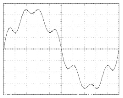
| Harmonic Order | Percentage | Phase |
| 5 | 9.80 | 0 |
| 7 | 15.80 | 0 |
| 8 | 2.16 | 0 |
DST02:
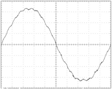
| Harmonic Order | Percentage | Phase |
| 3 | 1.44 | 0 |
| 7 | 1.47 | 0 |
| 19 | 1.95 | 0 |
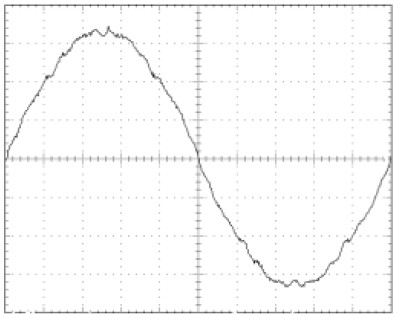
DST03:
| Harmonic Order | Percentage | Phase |
| 3 | 1.96 | 0 |
| 5 | 1.37 | 0 |
| 7 | 1.98 | 0 |
| 23 | 1.42 | 0 |
| 31 | 1.00 | 0 |
DST04:
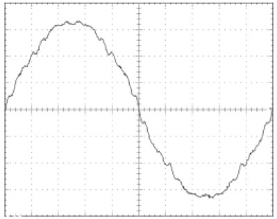
| Harmonic Order | Percentage | Phase |
| 3 | 2.45 | 0 |
| 5 | 1.88 | 0 |
| 7 | 2.46 | 0 |
| 23 | 1.95 | 0 |
| 25 | 1.09 | 0 |
| 31 | 1.52 | 0 |
| 33 | 1.09 | 0 |
DST05:
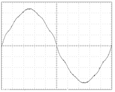
| Harmonic Order | Percentage | Phase |
| 3 | 1.10 | 0 |
| 5 | 2.80 | 0 |
| 7 | 1.40 | 0 |
| 9 | 2.30 | 0 |
| 11 | 1.50 | 0 |
DST06:
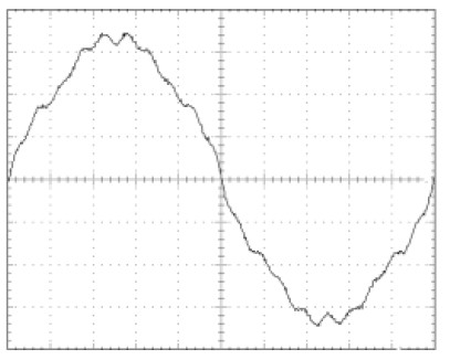
| Harmonic Order | Percentage | Phase |
| 3 | 1.60 | 0 |
| 5 | April 17 | 0 |
| 7 | 3.40 | 0 |
| 15 | 1.02 | 0 |
| 19 | 2.92 | 0 |
DST07:
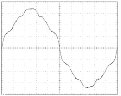
| Harmonic Order | Percentage | Phase |
| 3 | 2.17 | 0 |
| 5 | 5.59 | 0 |
| 7 | 2.79 | 0 |
| 9 | 4.56 | 0 |
| 11 | 2.92 | 0 |
| 15 | 1.35 | 0 |
| 21 | 0.99 | 0 |
DST08:
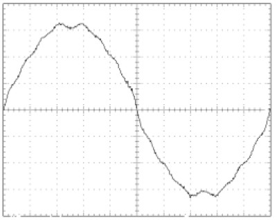
| Harmonic Order | Percentage | Phase |
| 3 | 4.86 | 0 |
| 5 | 1.58 | 0 |
| 7 | 2.64 | 0 |
| 11 | 1.37 | 0 |
| 15 | 1.95 | 0 |
| 17 | 1.06 | 0 |
DST09:
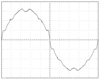
| Harmonic Order | Percentage | Phase |
| 3 | 7.72 | 0 |
| 5 | 2.39 | 0 |
| 7 | 4.01 | 0 |
| 11 | 2.07 | 0 |
| 13 | 1.03 | 0 |
| 15 | 2.94 | 0 |
| 17 | 1.59 | 0 |
| 19 | 1.00 | 0 |
| 21 | 1.04 | 0 |
| 23 | 1.19 | 0 |
| 25 | 1.03 | 0 |
DST10:
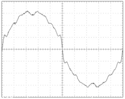
| Harmonic Order | Percentage | Phase |
| 3 | 9.78 | 0 |
| 5 | 3.19 | 0 |
| 7 | 5.37 | 0 |
| 9 | 1.17 | 0 |
| 11 | 2.76 | 0 |
| 13 | 1.37 | 0 |
| 15 | 3.92 | 0 |
| 17 | 2.13 | 0 |
| 19 | 1.34 | 0 |
| 21 | 1.39 | 0 |
| 23 | 1.59 | 0 |
| 25 | 1.36 | 0 |
DST11:
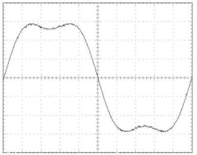
| Harmonic Order | Percentage | Phase |
| 3 | 17.72 | 0 |
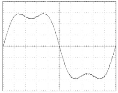
DST12:
| Harmonic Order | Percentage | Phase |
| 3 | 21.21 | 0 |
DST13:
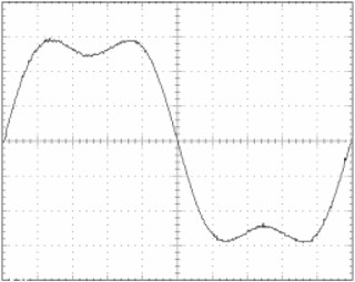
| Harmonic Order | Percentage | Phase |
| 3 | 24.48 | 0 |
DST14:
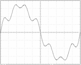
| Harmonic Order | Percentage | Phase |
| 2 | 2.19 | 0 |
| 5 | 9.83 | 0 |
| 7 | 15.76 | 0 |
| 8 | 2.34 | 0 |
DST15:
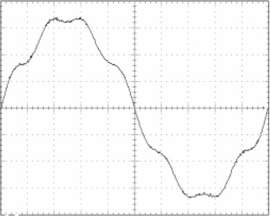
| Harmonic Order | Percentage | Phase |
| 2 | 1.04 | 0 |
| 5 | 4.90 | 0 |
| 7 | 7.86 | 0 |
| 8 | 1.14 | 0 |
DST16:
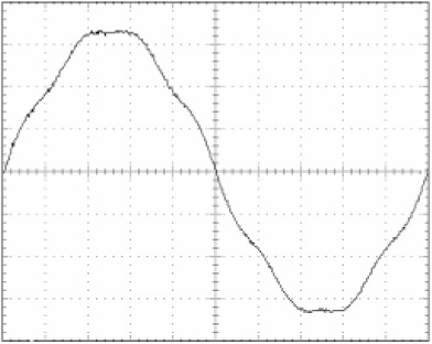
| Harmonic Order | Percentage | Phase |
| 5 | 2.42 | 0 |
| 7 | 3.91 | 0 |
DST17:
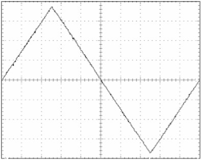
| Harmonic Order | Percentage | Phase |
| 3 | 11.08 | 180 |
| 5 | 4.05 | 0 |
| 7 | 2.03 | 180 |
| 9 | 1.27 | 0 |
DST18:
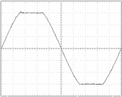
| Harmonic Order | Percentage | Phase |
| 3 | 7.16 | 0 |
| 5 | 3.46 | 180 |
DST19:
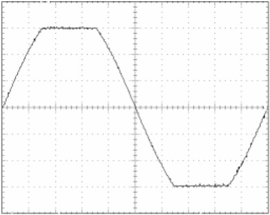
| Harmonic Order | Percentage | Phase |
| 3 | 8.07 | 0 |
| 5 | 3.55 | 180 |
| 9 | 0.96 | 0 |
| 13 | 0.92 | 180 |
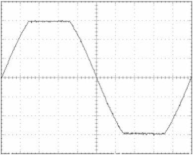
DST20:
| Harmonic Order | Percentage | Phase |
| 3 | 9.38 | 0 |
| 5 | 3.44 | 180 |
| 9 | 1.12 | 0 |
| 13 | 0.50 | 180 |
DST21:
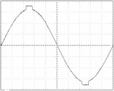
| Harmonic Order | Percentage | Phase |
| 3 | 2.06 | 180 |
| 5 | 1.77 | 0 |
| 7 | 1.62 | 180 |
| 9 | 1.23 | 0 |
| 11 | 0.91 | 180 |
| 13 | 0.54 | 0 |
| 23 | 0.51 | 0 |
| 25 | 0.53 | 180 |
DST22:
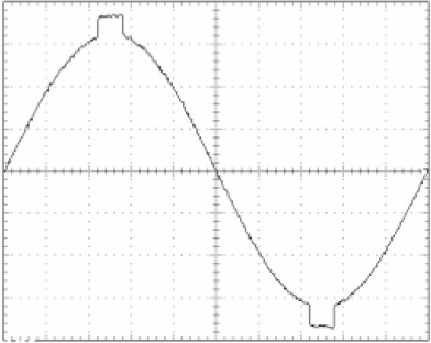
| Harmonic Order | Percentage | Phase |
| 3 | 3.08 | 180 |
| 5 | 2.72 | 0 |
| 7 | 2.43 | 180 |
| 9 | 1.97 | 0 |
| 11 | 1.41 | 180 |
| 13 | 0.86 | 0 |
| 21 | 0.62 | 180 |
| 23 | 0.73 | 0 |
| 25 | 0.77 | 180 |
| 27 | 0.69 | 0 |
| 29 | 0.56 | 180 |
DST23:
| Harmonic Order | Percentage | Phase |
| 2 | 0.13 | 180 |
| 3 | April 28 | 180 |
| 5 | 3.77 | 0 |
| 7 | 3.27 | 180 |
| 9 | 2.57 | 0 |
| 11 | 1.93 | 180 |
| 13 | 1.22 | 0 |
| 15 | 0.55 | 180 |
| 19 | 0.46 | 0 |
| 21 | 0.83 | 180 |
| 23 | 0.97 | 0 |
| 25 | 1.04 | 180 |
| 29 | 0.75 | 180 |
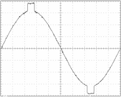
DST24:
| Harmonic Order | Percentage | Phase |
| 3 | 5.74 | 180 |
| 5 | 5.11 | 0 |
| 7 | 4.44 | 180 |
| 9 | 3.52 | 0 |
| 11 | 2.63 | 180 |
| 13 | 1.65 | 0 |
| 15 | 0.80 | 180 |
| 19 | 0.61 | 0 |
| 21 | 1.07 | 180 |
| 23 | 1.28 | 0 |
| 25 | 1.35 | 180 |
| 27 | 1.22 | 0 |
| 29 | 0.98 | 180 |
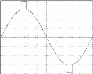
DST25:
| Harmonic Order | Percentage | Phase |
| 3 | 7.35 | 180 |
| 5 | 6.60 | 0 |
| 7 | 5.74 | 180 |
| 9 | 4.57 | 0 |
| 11 | 3.41 | 180 |
| 13 | 2.16 | 0 |
| 15 | 1.04 | 180 |
| 19 | 0.74 | 0 |
| 21 | 1.35 | 180 |
| 23 | 1.64 | 0 |
| 25 | 1.73 | 180 |
| 27 | 1.56 | 0 |
| 29 | 1.24 | 180 |
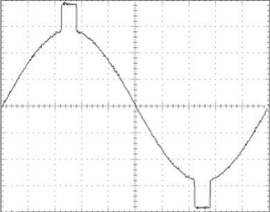
DST26:
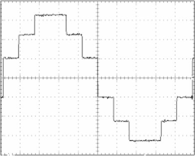
| Harmonic Order | Percentage | Phase |
| 5 | 3.41 | 0 |
| 7 | 2.55 | 0 |
| 11 | 9.22 | 0 |
| 13 | 7.68 | 0 |
| 17 | 0.90 | 0 |
| 19 | 0.90 | 0 |
| 23 | 3.88 | 0 |
| 25 | 3.56 | 0 |
| 31 | 0.50 | 0 |
| 35 | 2.34 | 0 |
| 37 | 2.21 | 0 |
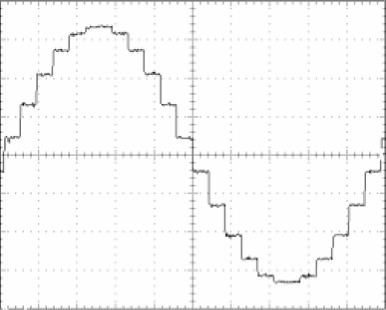
DST27:
| Harmonic Order | Percentage | Phase |
| 21 | 1.24 | 0 |
| 23 | 4.91 | 0 |
| 25 | 2.21 | 0 |
DST28:
| Harmonic Order | Percentage | Phase |
| 3 | 33.39 | 0 |
| 5 | January 20 | 0 |
| 7 | 13.76 | 0 |
| 9 | 10.70 | 0 |
| 11 | 8.39 | 0 |
| 13 | 7.06 | 0 |
| 15 | 5.86 | 0 |
| 17 | 4.86 | 0 |
| 19 | 4.86 | 0 |
| 21 | 4.52 | 0 |
| 23 | 4.00 | 0 |
| 25 | 3.49 | 0 |
| 27 | 2.91 | 0 |
| 29 | 2.45 | 0 |
| 31 | 1.94 | 0 |
| 33 | 1.95 | 0 |
| 35 | 1.91 | 0 |
| 37 | 1.89 | 0 |
| 39 | 1.83 | 0 |
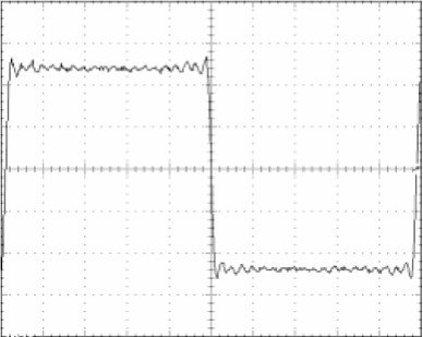
DST29:
| Harmonic Order | Percentage | Phase |
| 3 | 33.39 | 0 |
| 5 | January 20 | 0 |
| 7 | 13.75 | 0 |
| 9 | 10.71 | 0 |
| 11 | 8.37 | 0 |
| 13 | 7.05 | 0 |
| 15 | 5.84 | 0 |
| 17 | 4.84 | 0 |
| 19 | 4.83 | 0 |
| 21 | 4.48 | 0 |
| 23 | 3.93 | 0 |
| 25 | 0.89 | 0 |
| 27 | 0.92 | 0 |
| 29 | 0.94 | 0 |
| 31 | 0.94 | 0 |
| 33 | 0.94 | 0 |
| 35 | 0.93 | 0 |
| 37 | 0.92 | 0 |
| 39 | 0.91 | 0 |
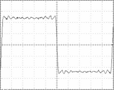
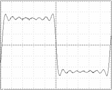
DST30:
| Harmonic Order | Percentage | Phase |
| 3 | 33.39 | 0 |
| 5 | January 20 | 0 |
| 7 | 13.74 | 0 |
| 9 | 10.67 | 0 |
| 11 | 8.33 | 0 |
| 13 | 6.99 | 0 |
| 15 | 5.26 | 0 |