
 English
 中文简体
中文简体 English
 Русский
 Español
 Português
 Türkçe
 العربية
 Deutsch
 Polski
 Italiano
 Français
 한국어
한국어 ไทย
ไทย Tiếng Việt
 日本語
日本語





























Automotive Transient Emission Test System
User's Manual
Applicable LISUN models: LIS-TEMI-100A、LIS-TEMI-150A、LIS-TEMI-50A
1. Basic Understanding of Equipment
1.1 Model Classification
| LISUN Model | LIS-TEMI-50A | LIS-TEMI-100A | LIS-TEMI-150A |
|---|---|---|---|
| DUT Capacity | 80 V/50 A | 80 V/100 A | 80 V/150 A |
| Product Name | Automotive Transient Emission Test System (Power Cables) | ||
| Monitoring Interface | N-type 1:1 coaxial terminal output | ||
| Resistors in Parallel | [Rs]: Open circuit, 10 Ω, 20 Ω, 40 Ω, 120 Ω | ||
| Trigger Method | Automatic, One-Time, External Trigger | ||
| Mode Selection | Mechanical switches, electronic switches | ||
| Instrument Grounding Connection Methods | Banana Plug Cables ≤ 10 mm | ||
| Artificial Mains Network Parameters | |||
| Frequency | 0.1 MHz–100 MHz | ||
| Capacitance | 0.1 μF | ||
| Impedance | 5 μH||50 Ω, conforms to the impedance curve specified in ISO 7637-2 | ||
| DC Resistance | <5 mΩ | ||
| Electronic Switch Specifications | |||
| Start and Stop Times | 0.01–99.99 s + (10% + 10 ms) | ||
| Operating Hours | 300 ns + 20% @ load 50 μH/0.6 Ω | ||
| Transient Protection Voltage | 440 V | ||
| Mechanical Switch Specifications | |||
| Start and Stop Times | 0.01–99.99 s + (10% + 10 ms) | ||
| Contact Points | High-purity silver, with no contact inhibition | ||
| Action Time | Close: 20 ms; Open: 10 ms | ||
1.2 Applicable Standards
ISO 7637-2, “Road Vehicles—Electrical Disturbances Caused by Conduction and Coupling—Part 2: Electrical Transients Conducted Along Power Lines,” Clause 4.3, Appendix B
GB/T 21437.2-2021 “Road Vehicles—Test Methods for Electromagnetic Disturbances Caused by Conduction and Coupling in Electrical/Electronic Components—Part 2: Conducted Transient Emissions and Immunity Along Power Lines,” Clause 4.3, Appendix B
1.3 Application Scenarios
The LIS-TEMI Series Automotive Transient Emission Test System is a power line transient conducted emission test bench specifically designed for the research and development of in-vehicle electrical and electronic components. It is used to evaluate the level of voltage transient disturbances generated by the device under test (hereinafter referred to as DUT) during power on/off transitions and to verify whether the product complies with relevant automotive electromagnetic compatibility standards.
The system simulates the impedance characteristics of vehicle wiring harnesses using an artificial network. Combined with high-precision switching modules and adjustable shunt resistors, it can perform two types of transient emission Test: slow pulses (millisecond-level) and fast pulses (microsecond-level). It is widely used by automotive parts manufacturers and third-party testing laboratories for electromagnetic compatibility (EMC) research and development as well as compliance verification.
1.4 Core Testing Capabilities
1.4.1 Slow-Pulse Transient Emission Test
For voltage transient disturbances in the millisecond range and slower, this test is suitable for DUTs with inductive loads driven by internal switches, and simulates slow transient disturbance emission Test caused by the vehicle ignition switch or a relay opening.
1.4.2 Fast-Pulse Transient Emission Test
Designed for fast voltage transient disturbances in the microsecond-to-millisecond range, Test is suitable for DUTs without internal switches and simulates fast transient disturbance emissions caused by high-speed switching operations.
2. Precautions for Use
2.1 Environmental Requirements
Ambient temperature: 23 °C ± 5 °C; relative humidity: 45–75%, non-condensing; altitude: ≤2000 m; no strong vibrations or electromagnetic interference in the vicinity; use of the equipment in dusty or flammable and explosive environments is strictly prohibited.
2.2 Power Supply Requirements
Input power supply: AC 220 V ±10%, 50 Hz; Input power: ≤1 kW; The power supply must be reliably grounded, with a grounding resistance of ≤4 Ω; It is recommended to use a voltage-stabilized power supply to prevent power grid fluctuations from affecting test accuracy.
2.3 Wiring Principles
Use power cables with the specified wire gauge to prevent overheating under high current conditions; keep Test as short as possible and route them in parallel to minimize the effects of parasitic parameters; ensure the DUT (Device Under Test) enclosure is reliably connected to the equipment’s protective ground; and route signal and power cables separately to avoid cross-interference.
2.4 Operational Safety Guidelines
Wear insulated protective gear; Test testing, ensure that all connections are secure and that there are no exposed conductors; do not touch or plug in or unplug any wiring harnesses or cables during Test; if you hear unusual noises, smell an unusual odor, or see smoke, immediately turn off the power.
3. Equipment Overview
3.1 System Hardware Components
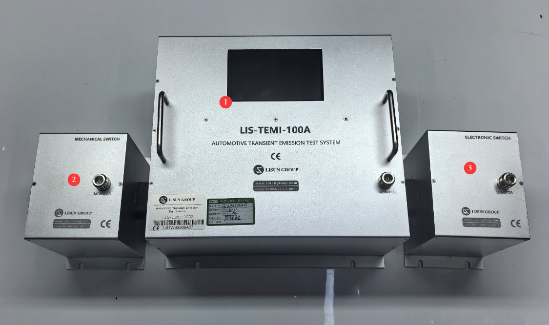
3.1.1 Host Computer
See Figure 3-1.
| Number | Note |
|---|---|
| ① | Main Control and Manual Network, including a touchscreen and an N-type monitoring interface |
| ② | Mechanical switch with an N-type monitoring interface |
| ③ | Electronic Switch, with N-Type Monitoring Interface |
3.1.2 Accessories
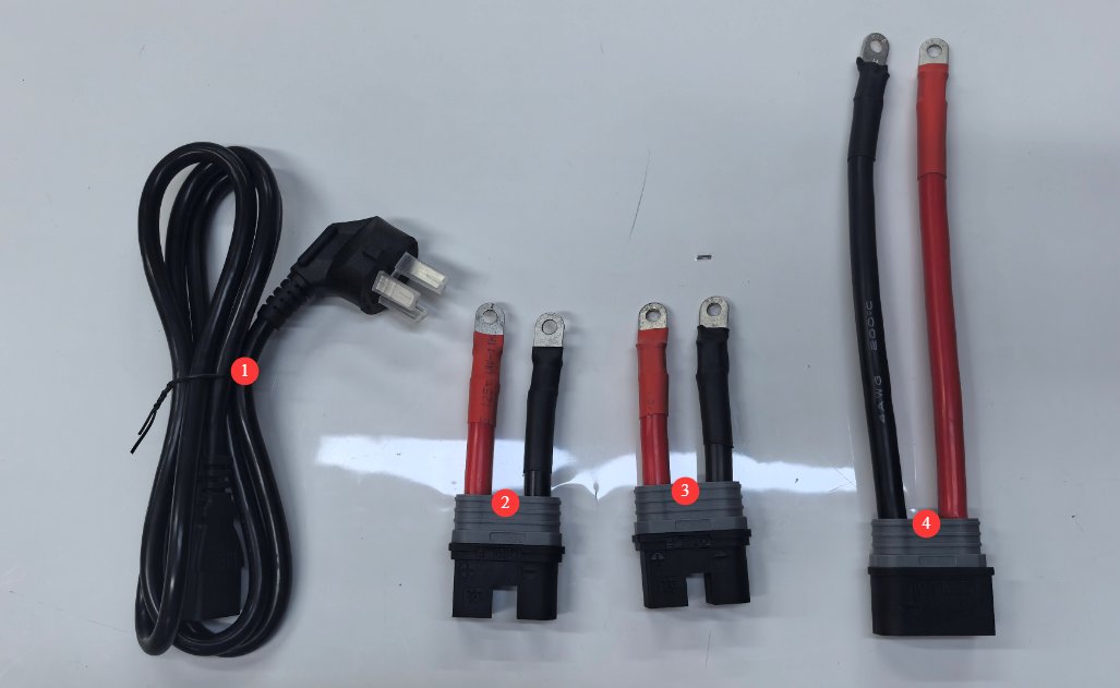
See Figure 3-2.
| Number | Note |
|---|---|
| ① | Power Cord |
| ②③ | 100mm Standard Connecting Cable |
| ④ | 200mm Standard Connecting Cable |
3.2 Introduction to the Touchscreen Program
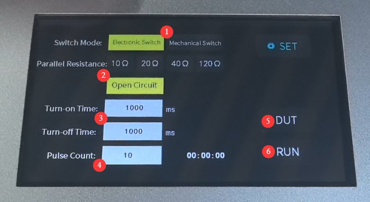
See Figure 3-3.
| Number | Note |
|---|---|
| ① | Switch Mode Selection: To switch between electronic and mechanical switches, the setting must match the hardware of the switch module actually connected. |
| ② | Parallel resistance options: 10 Ω, 20 Ω, 40 Ω, 120 Ω, or open circuit. If “open circuit” is selected, the customer may connect a parallel resistor of any other value. |
| ③ | Settings for Connection Duration (On/Off) |
| ④ | Pulse Count Setting |
| ⑤ | DUT Power Supply Control: Controlling the DUT’s Power Supply Output |
| ⑥ | Operational Control, Start/Stop Pulse Test |
4. Procedures for Automotive Electronic Transient Emission Testing
4.1 Preparation of the Test Environment
4.1.1 Site and Grounding Requirements
Tests must be conducted in an Electromagnetic Shielding Cabinet or a laboratory with a stable electromagnetic environment to prevent external electromagnetic interference from affecting the Test results.
Place a metal grounding plate with a thickness of ≥2 mm; the plate must be large enough to cover all Test equipment and the DUT, and it must be securely connected to the laboratory grounding system, with a grounding resistance of ≤4 Ω.
Artificial networks and switch modules are placed directly on the metal ground plane. The DUT’s connection cables must be routed parallel to the ground plane at a height of 50 mm ± 5 mm above it.
4.1.2 Electromagnetic Environment Requirements
The test area must be located away from sources of strong electromagnetic interference, such as high-power motors, variable-frequency drives, and high-frequency transmitting equipment.
During testing, avoid turning high-power laboratory equipment on or off to prevent power grid fluctuations from interfering with Test.
4.1.3 Preparation of Auxiliary Equipment
Digital Oscilloscope: Minimum sampling rate of 2 GS/s, bandwidth of 400 MHz, and input sensitivity of at least 5 mV/division; power on 30 minutes in advance to allow for warm-up; voltage probes: must be suitable for the test voltage range, have proper bandwidth matching, have the attenuation ratio set correctly, and be calibrated in advance.
DUT DC power supply or battery: The output voltage and current must meet the DUT’s rated operating requirements, and the voltage regulation accuracy must be ≤±0.5%.
Insulated support block: 50 mm ± 5 mm thick, used to raise the DUT and prevent direct contact with the ground plate.
4.2 Test Plan Approval
Test Type Selection
Select the Test type based on the DUT type and Test standard requirements: For DUTs with internal mechanical/electronic switches that drive inductive loads, select Test slow-pulse test; for DUTs without internal switches, select Test fast-pulse test.
Type Testing / Test: Use mechanical switches for slow pulses and electronic switches for fast pulses; there is no need to Test using both types of switches.
Parameter Settings
| Parameters | Slow Pulse | Rapid Pulse |
|---|---|---|
| Resistors in Parallel | Typical values are 10Ω, 20Ω, 40Ω, and 120Ω. For special operating conditions, you can select the “open circuit” setting and connect an external resistor with a custom resistance value. For 12V automotive systems, 20Ω to 50Ω is commonly used; for 24V systems, 40Ω to 120Ω is commonly used. | |
| Connection Duration | DUTs are typically inductive loads with internal switches, and their current rise time is relatively long; the turn-on time is usually set to 500 ms to 5 s, depending on the time it takes for the DUT load to reach steady state. | DUTs are typically resistive or slightly inductive loads without internal switches; they reach steady state faster, so the turn-on time can be appropriately shortened—usually set to 100 ms to 1 s—though the core principle remains ensuring stable DUT operation. |
| Duration of Disconnection | Inductive loads take a long time to demagnetize; the turn-off time is typically set to be at least as long as the turn-on time, usually ranging from 500 ms to 10 s, to ensure the load is fully reset. | The load energy is low, demagnetization is fast, and the disconnection time can be set to ≥100 ms; it is also necessary to ensure that the load is fully reset. |
| Number of pulses | Since the contact state varies slightly each time, Test typically performed 10 to 100 times. | High waveform consistency; typically Test to 50 times |
4.3 Wiring Methods
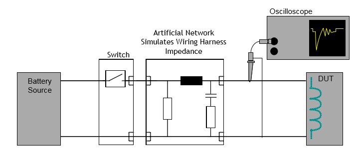
4.3.1 Wiring Diagram for the Slow-Pulse Test
See Figure 4-1 for the wiring diagram.
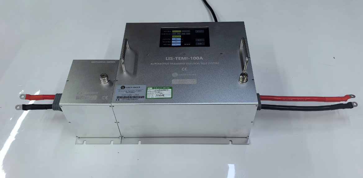
Connect the LIS-TEMI as shown in Figure 4-2. From left to right: DUT DC power supply or battery, 100-mm standard connecting cable, mechanical switch, main control unit and manual network, 200-mm standard connecting cable, and DUT.
4.3.2 Wiring Diagram for the Rapid Pulse Test
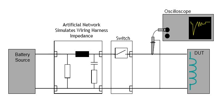
See Figure 4-3 for the wiring diagram.
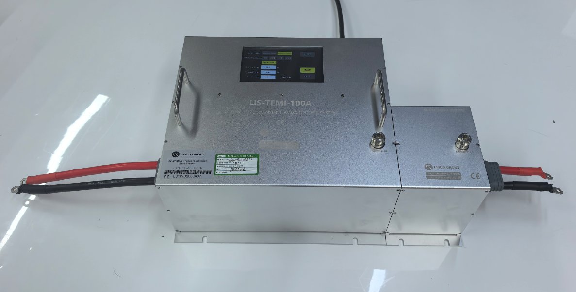
Connect the LIS-TEMI as shown in Figure 4-4. From left to right: DUT DC power supply or battery, 200-mm standard connection cable, master controller and manual network, electronic switch, 100-mm standard connection cable, and DUT.
4.4 Evaluation of Test Results
Determination is based on the following three rules; if all are met, Test is considered passed.
| Rules for Determination | Compliance Statement |
|---|---|
| Transient Emission Amplitude | The peak values of the positive transient voltage and the negative transient voltage must be tested separately, and both must meet the limit requirements. |
| Process Requirements | The DUT functioned normally throughout Test |
| Final Inspection Requirements | No permanent damage was found after Test |
5. Daily Maintenance and Care of Equipment
5.1 Daily Use and Maintenance
5.1.1 Clean before and after each use
Before Use: Wipe the device’s surface, screen, and ports with a dry, soft cloth to remove dust and stains. Do not use corrosive cleaning agents.
After use: Clean the Test bench, organize the cables, and place dust covers over the device ports to prevent dust from entering the interior.
Screen Cleaning: Gently wipe the screen with a dedicated screen-cleaning cloth, and avoid scratching the touchscreen with hard objects.
Routine Visual and Interface Inspections
Before each use, check the following: the equipment housing for deformation, dents, or rust; the power and signal connector pins for bending, oxidation, or looseness; the power cable and standard Test cables for damage or aging, and the plugs for deformation; and the grounding terminal for a secure connection and signs of oxidation.
5.2 Long-Term Storage and Maintenance
Storage Environment Requirements
Storage temperature: -10°C to 50°C; relative humidity: ≤70%, no condensation; storage environment: dry, well-ventilated, dust-free, free of corrosive gases, and away from direct sunlight and heat sources; the equipment must be stored in its original packaging and placed on a raised surface to prevent moisture exposure.
5.2.2 Preprocessing Before Storage
Clean the equipment thoroughly to remove surface dust and stains; place dust caps over all ports, and neatly organize and bundle the cables to prevent kinks; disconnect all external connections and place a dust bag over the equipment; place desiccant inside the packaging to prevent moisture damage.
5.2.3 Requirements for Periodic Power Supply During Long-Term Storage
If the equipment is stored for more than 3 months, remove it from storage, plug it in, and let it warm up for 1 hour to remove internal moisture. After plugging it in, perform Test to ensure the equipment is operating normally. Replace the desiccant regularly to ensure the storage environment remains dry.
5.3 Calibration Interval Requirements
To ensure the measurement accuracy and operational reliability of the equipment, it is recommended that it be sent periodically to a qualified third-party metrology laboratory for calibration. The recommended calibration interval is 12 months. Users may determine the specific calibration interval based on frequency of use, environmental conditions, and quality system requirements.
6. Troubleshooting and Resolving Common Problems
| Failure Symptoms | Possible Causes | Procedure |
|---|---|---|
| The device won’t turn on | The input power supply main power switch on the rear panel is not turned on, or the fuse has blown. | Turn on the input power supply switch located at the power cord receptacle on the back of the device; check the fuse, and if it has blown, replace it with a fuse of the same rating. |
| Touchscreen Malfunction After Power-Up | System freeze, loose ribbon cable | If the problem persists after restarting, disconnect the power, then follow our instructions to remove the device casing and check whether the touchscreen ribbon cable is loose. |
| Switch Mode Failure | Incorrect Switch Module Connection | Please verify that the switch type selected on the touchscreen matches the type of switch actually connected. |
| Pulse Output Abnormality | Switch Mode Error, Parallel Resistance Range Error, DUT Malfunction | Verify that the switch mode selected on the touchscreen matches the switch module that is actually connected; verify that the appropriate parallel resistor setting is used; verify that the DUT operates normally after the switch is turned on. |
| Unusual Noise When Operating the Switch | Contact oxidation and ablation; DUT voltage and current out of limits | If severe ablation due to oxidation occurs, replace the parts; do not exceed the load capacity under any circumstances. |