
 English
 中文简体
中文简体 English
 Русский
 Español
 Português
 Türkçe
 العربية
 Deutsch
 Polski
 Italiano
 Français
 한국어
한국어 ไทย
ไทย Tiếng Việt
 日本語
日本語





























HBM/MM ESD Simulators for IC Testing
User's Manual
Applicable LISUN models: ESD-883D
1. Basic Understanding of Equipment
1.1 Product Overview
The ESD-883D Semiconductor Electrostatic Discharge Simulator , also known as a Semiconductor ESD Immunity Tester, is a high-precision electrostatic discharge (ESD) immunity testing device designed by LISUN specifically for semiconductor devices (such as chips, diodes, transistors, and IC modules). The device can replicate electrostatic discharge phenomena caused by a charged human body or equipment. By injecting standardized high-voltage pulses, it evaluates the tolerance limits of semiconductor devices to electrostatic shocks, It proactively identifies latent faults in devices caused by static electricity, such as gate breakdown and PN junction damage, providing critical test data for the reliability design and factory quality inspection of semiconductor devices.
1.2 Applicable Standards and Test Models
1.2.1 Human Body Model (HBM)
Simulates the electrostatic discharge generated when a human body comes into contact with a semiconductor device. Applicable standards include:
ANSI/ESD STM5.1-2007, ANSI/ESDA/JEDEC JS-001-2024, IEC 60749-26:2018, EIA/JESD22-A114-B, MIL-STD-883 Method 3015, AEC-Q100-002, GB/T 4937.26-2023.
1.2.2 Machine Discharge Model (MM)
Electrostatic discharge (ESD) that occurs when automated equipment (such as surface-mount machines and probe stations) comes into contact with chips; applicable standards include:
ANSI/ESD STM5.2-2013, IEC 60749-27:2012, EIA/JESD22-A115-A, AEC-Q100-003, GB/T 4937.27-2023.
1.3 Key Technical Specifications
| Project | Human Body Model (HBM) | Machine Discharge Mode (MM) |
|---|---|---|
| Output Voltage Range | 50 V–8 kV ±5% | 50 V to 2 kV ±5% |
| Output Polarity | Positive, Negative, Alternating Positive and Negative | Positive, Negative, Alternating Positive and Negative |
| Discharge Capacitor | 100 pF ±10% | 200 pF ±10% |
| Discharge Resistor | 1500 Ω ±10% | 0 Ω |
| Discharge Interval | 1–99 seconds | 1–99 seconds |
| Number of Discharges | 1–999 times | 1–999 times |
| Trigger Mode | Single, Count, Host-Triggered | Single, Count, Host Self-Trigger |
1.4 Typical Application Areas
Semiconductor Design and R& D: Chip reliability verification, electrostatic sensitivity testing of new materials; Semiconductor Packaging and Manufacturing: Post-packaging final inspection; Automotive Electronics Semiconductors: Electrostatic testing of automotive chips, IGBT module testing; Military and High-Reliability Semiconductors: Testing of military chips and aerospace semiconductors; Third-Party Testing and Certification: Compliance certification testing, verification of compliance with standards; Consumer Electronics Semiconductors: Testing of consumer-grade chips and semiconductor components.
2. Safety Precautions
2.1 Work Environment Requirements
Operating temperature: 15°C to 35°C; operating relative humidity: 30% to 60%. Do not use in environments with high humidity or condensation to prevent high-voltage arcing.
There must be no strong electromagnetic interference, no sources of vibration, no flammable or explosive materials, and no corrosive gases in the surrounding area.
Place it on a stable work surface; avoid tilting or inverting it, and keep it away from sources of vibration.
The equipment must be placed at least 500 mm away from walls and surrounding structures (such as other test equipment and shelving) to facilitate maintenance; at least 1000 mm of space must be left in front of the equipment to ensure smooth operation, and there must be no obstructions in the surrounding area.
2.2 High-Voltage Safety Standards
2.2.1 Security Check
Verify that the power supply is compatible with the equipment, ensure that the power supply is properly grounded, and check that the grounding wire is free of damage or looseness;
Grounding Requirements: The host unit’s protective grounding terminal (PGND) must be connected to ground using a grounding conductor. The grounding resistance must be ≤4Ω, and the grounding cable must be securely connected without any looseness or breaks.
2.2.2 Safety Requirements for Operational Procedures
Operators must undergo professional training and be familiar with this manual and the relevant standards. Non-professionals are prohibited from operating or disassembling the equipment. The equipment contains high-voltage circuits; opening the cover may pose an electric shock hazard. Contact the manufacturer’s technical staff for repairs;
After the equipment is powered on, do not touch the test bench, high-voltage cables, test leads, or other related components to prevent electric shock;
Operators should ensure their hands are dry and free of metal jewelry; it is recommended that they wear insulated gloves while operating the equipment;
Do not eat or drink during the test to prevent accidents caused by electric shock;
When multiple people are involved, clearly define roles and responsibilities, and confirm them with each other before starting the test to avoid errors.
2.3 Equipment Safety Standards
Before connecting or disconnecting high-voltage cables, you must turn off the main unit’s power and wait at least 5 minutes to ensure that the internal capacitors are completely discharged;
When inserting a high-voltage plug into an outlet, align it with the positioning pins. Never force the plug into the outlet if it is not properly aligned, to avoid damaging the internal copper pins;
If you discover damage to the high-voltage cable or loose connectors, stop using it immediately and contact customer service to have it replaced;
Do not suddenly disconnect the power or plug or unplug high-voltage connectors while the equipment is running, to avoid damaging the high-voltage modules;
Do not scratch the touchscreen with hard objects, and do not press the screen with sharp objects;
Avoid bumping the equipment during testing to prevent the device under test from shifting, which could cause test failures or probe damage.
2.4 Other
For matters not covered in this manual, please proceed with caution or contact us.
3. Equipment Overview and Wiring
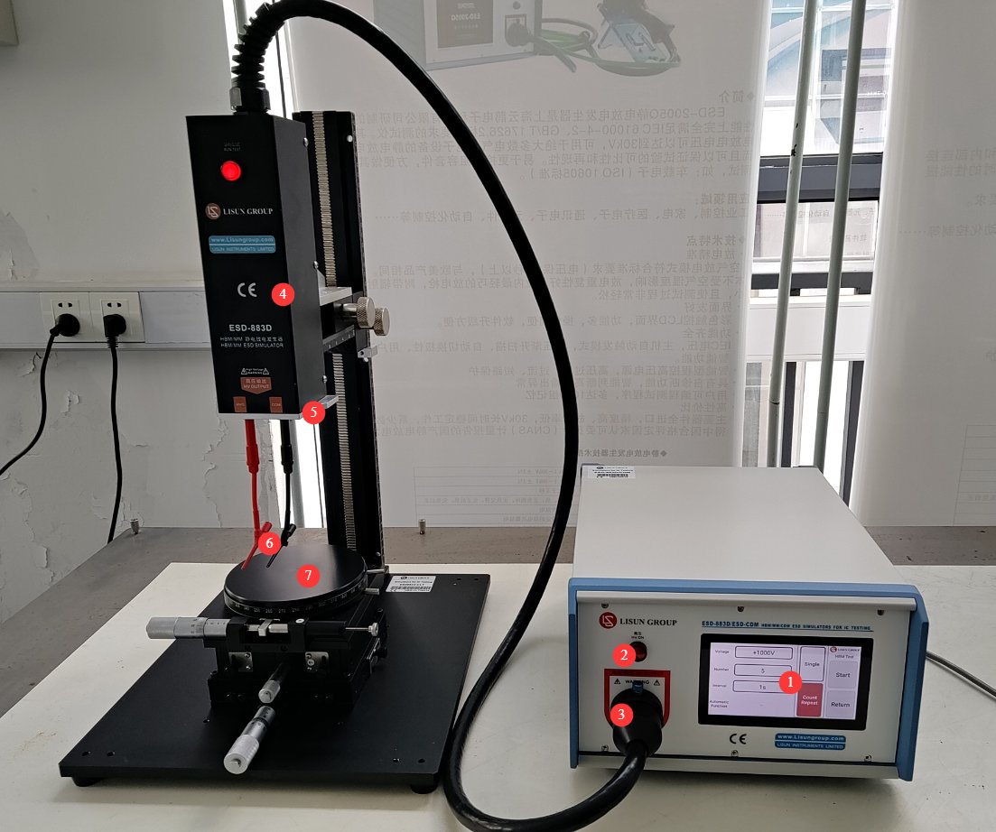
3.1 Front View
See Figure 3-1.
| Number | Note |
|---|---|
| Electrostatic Discharge Simulator | |
| ① | Touchscreen |
| ② | High-Voltage Indicator Light |
| ③ | High-voltage connection. Lift the positioning pin, align the groove in the discharge tower’s high-voltage plug with the positioning pin, and slowly insert it all the way to the bottom. Then lower the positioning pin to lock the high-voltage plug in place. |
| HBM/MM Electrostatic Discharge Tower | |
| ④ | Adjustable-height stand |
| ⑤ | Discharge module: Simply unplug or plug it in to replace the HBM or MM discharge module. |
| ⑥ | A standard-length test lead with the banana plug end inserted into the discharge module and the small clip end clamped onto the device under test |
| ⑦ | Standard test stand, with adjustable position and height |
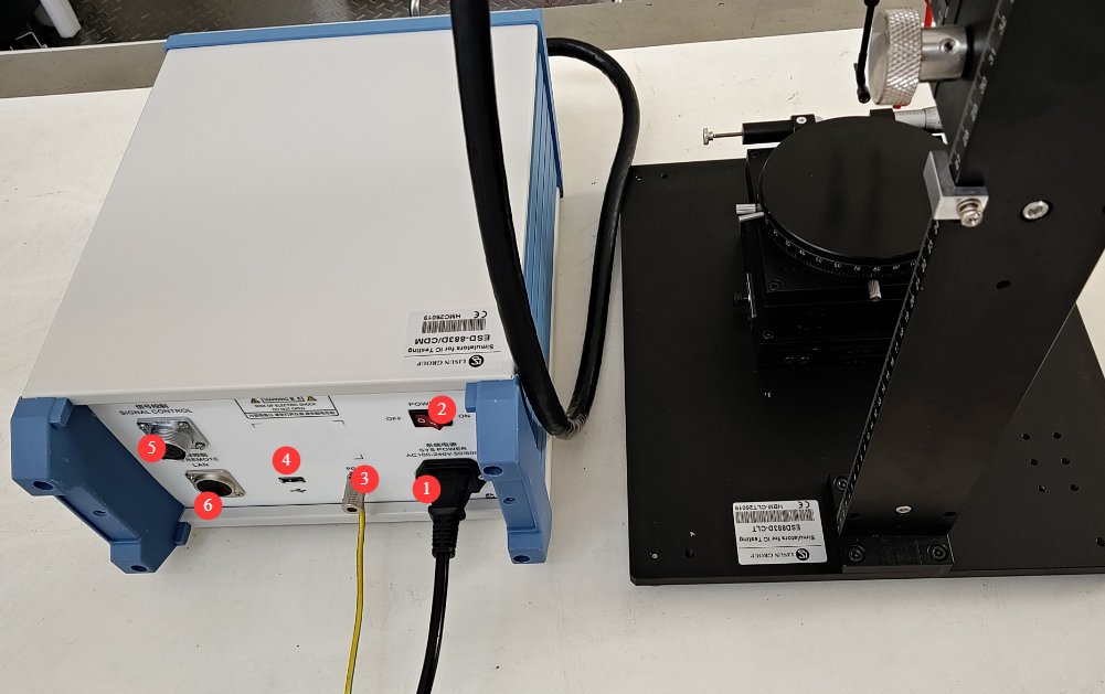
3.2 Rear View
See Figure 3-2.
| Number | Note |
|---|---|
| ① | Power cord receptacle (with fuse) for connecting the device to an appropriate power source |
| ② | Power Switch |
| ③ | PGND: Protective ground terminal; connect to earth using a ground wire. |
| ④ | USB port: Can be used to connect a USB mouse to control the touchscreen, or to connect a USB flash drive to update the software. |
| ⑤ | Signal cable used to connect the CDM electrostatic discharge tower; do not connect when the CDM electrostatic discharge tower is not in use. |
| ⑥ | LAN port, spare |
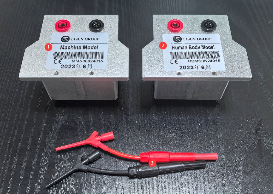
3.3 Major Components
See Figure 3-3.
| Number | Note |
|---|---|
| ① | MM Discharge Module |
| ② | HBM Discharge Module |
| ③ | Standard Test Line |
3.4 Replacing the Discharge Module and Discharge Tower
The HBM/MM discharge tower can accommodate only one discharge module, which can be replaced manually. The Electrostatic Discharge Simulator can be connected to discharge towers designed for different tests. If you need to replace the discharge tower for testing, please strictly follow the operating procedures below.
| ① | ② | ③ |
|---|---|---|
| Verify that the Electrostatic Discharge Simulator is in the “Test Stopped” state, then shut it down. | If you need to replace the discharge module, refer to Section 3.1 for replacement instructions. | After replacing it, turn on the device and run the new test. |
| If you need to replace the discharge tower, disconnect all cables between the original discharge tower and the Electrostatic Discharge Simulator, and then reconnect all cables between the new discharge tower and the Electrostatic Discharge Simulator. |
4. Introduction to the Touchscreen Program
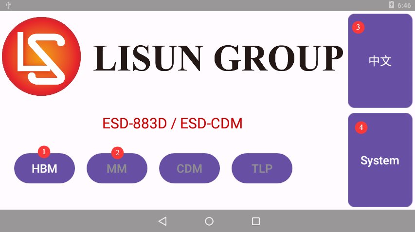
4.1 Initial Screen
See Figure 4-1.
| Number | Note |
|---|---|
| ①② | Depending on the discharge module you have installed, either “HBM” or “MM” will automatically appear here; click on it to access the corresponding test interface. Note: The device displays “MM” by default; that is, even if no discharge module is installed, “MM” will still appear as available. |
| ③ | Switch Between Chinese and English |
| ④ | Product Information Page |
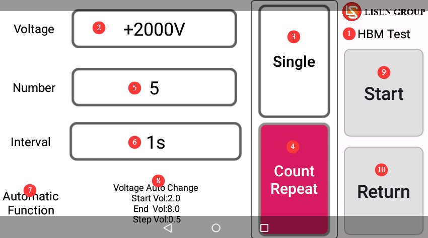
4.2 HBM/MM Test Interface
See Figure 4-2.
| Number | Note |
|---|---|
| ① | Displays the currently used discharge module: HBM or MM |
| ② | The test voltage and polarity can be set |
| ③ | If you want to run a single test, select “Single Test.” |
| ④ | If you want to perform continuous testing, select “Continuous Testing.” |
| ⑤ | You can set the number of tests; this is limited to consecutive tests only. |
| ⑥ | The interval time can be set; this feature is available only for continuous testing. |
| ⑦ | Automatic feature options—click to configure them if needed |
| ⑧ | The current automatic setting is configured such that, after clicking to start the test, the test begins at 2 kV. Once the test is complete, the system automatically advances to 2.5 kV in 0.5 kV increments as set. After charging is complete, you must manually click to continue the test until all tests are finished. |
| ⑨ | Start/Stop Test |
| ⑩ | Return to the Home Screen |
5. HBM/MM Electrostatic Discharge Testing
5.1 Pre-commissioning of the Discharge Tower
5.1.1 Installation of the HBM/MM Discharge Module
Install the correct discharge module according to the test requirements.
5.1.2 Placement Requirements for the Device Under Test
Operators must wear antistatic wristbands and antistatic clothing to prevent static electricity from their bodies from damaging the devices under test.
Based on the actual locations of the device under test and the test cables, adjust the height and horizontal position of the test bench so that, once the cables are connected to the test points on the device under test, the device sits securely on the test bench.
5.2 Recommended Standard Test Parameters
| Test Level | HBM Voltage | Typical Use Cases |
|---|---|---|
| Level 1 | 500 V | High-Sensitivity Devices |
| Level 2 | 1 kV | General-Purpose Sensors |
| Level 3 | 2 kV | Standard Components |
| Level 4 | 4 kV | Anti-static Devices |
| Level 5 | 8 kV | Highly Electrostatic-Resistant Components |
| Test Level | MM Voltage | Typical Use Cases |
|---|---|---|
| Low-level | 100V | High-Sensitivity Devices |
| Intermediate | 200 V | Standard Components |
| High Level | 500 V | Anti-static Components |
5.3 Starting/Stopping the Test
Set the test parameters according to Sections 4.2 and 5.2, and start the test. If any abnormalities occur during the test, press the stop button to halt the test, make the necessary adjustments, and retry. After the test is complete, ensure that any internal residual charge is completely discharged, and remove the device under test. If the equipment will not be used again that day, turn it off.
5.4 Interpretation of Test Results
All standards follow a unified testing and evaluation logic:
| Number | Note |
|---|---|
| Benchmarking | Before HBM/MM discharge, complete measurements of all parameters under the conditions specified in the standard and record the reference values. |
| Discharge Test | Complete the discharge cycle with the specified voltage, polarity, and number of cycles as required by the standard |
| Comparison of Retests | After discharge, remeasure all parameters under conditions identical to those of the baseline. |
| Failure Determination | If any parameter exceeds the specifications, the device malfunctions, or there is physical damage, the device under test is deemed to have failed. |
| Level Confirmation | The highest voltage at which none of the samples failed shall be used as the final HBM/MM withstand rating for the device under test. |
6. Daily Maintenance and Care of Equipment
6.1 Daily Cleaning and Maintenance
After each test, wipe dust from the main unit housing, touchscreen, and discharge tower surface with a clean, soft cloth to keep the equipment clean; use a dedicated screen-cleaning cloth to clean the touchscreen. Do not use organic solvents such as acetone, and do not spray water directly onto the screen to clean it; Clean dust and foreign objects from the test bench surface weekly; if test cable connectors are soiled, gently wipe them with a lint-free cotton swab dipped in a small amount of anhydrous ethanol, and allow them to air dry before use.
6.2 Items for Regular Inspection
6.2.1 Electrical Connection Inspection
Inspection Frequency: Once a month; Inspection Items: Check whether the power cords, high-voltage cables, and grounding cable connectors are loose, oxidized, or damaged; Remedial Actions: Tighten any loose connectors immediately; gently sand off any oxidation with fine-grit sandpaper; and replace any damaged cables immediately.
6.2.2 Mechanical Structure Inspection
Inspection Frequency: Once a month; Inspection Items: Check whether the test bench adjustment knobs turn smoothly and whether the limit blocks on the height-adjustable stand are secure; Check the discharge module for visible damage and inspect the contact points for dirt; Remedial Actions: Apply a small amount of silicone grease to lubricate the adjustment mechanism; if the contact points on the discharge module are dirty, gently wipe them with a clean, soft cloth or a lint-free cotton swab dipped in a small amount of anhydrous ethanol, then allow them to air dry before use.
6.3 Long-Term Storage Requirements
Before long-term storage, clean the entire surface of the unit and unplug all external cables; cover the unit with a dust cover and store it in a dry, well-ventilated environment free of corrosive gases; the storage environment should have a temperature of 0°C to 40°C and a relative humidity of ≤70%; avoid direct sunlight; Every 3 months, power on the device and leave it in standby mode for 30 minutes to remove moisture and protect the high-voltage modules.
6.4 Calibration Interval Requirements
To ensure the measurement accuracy and operational reliability of the equipment, it is recommended that it be sent periodically to a qualified third-party metrology laboratory for calibration. The recommended calibration interval is 12 months. Users may determine the specific calibration interval based on frequency of use, environmental conditions, and quality system requirements.
7. Troubleshooting and Resolving Common Problems
7.1 Power-Related Faults
| Fault Symptoms | Possible Causes | Procedure |
|---|---|---|
| No display when powered on; the power indicator light does not come on | The power cord is not plugged in securely; the fuse has blown. | Check the power cord connections; after turning off the power, replace the fuse with one of the same rating. |
| Touchscreen Not Responding | There are stains on the screen, and the system is malfunctioning. | Clean the screen surface; restart the device |
7.2 High-Voltage Faults
| Fault Symptoms | Possible Causes | Procedure |
|---|---|---|
| High voltage cannot be loaded after clicking “Start” | High-voltage cables are not properly connected, discharge modules are not properly installed, or there is poor contact | After the power is turned off, unplug and replug the high-voltage cable, then tighten it; ensure that the discharge module contacts are making good contact, and reinstall the discharge module. |
7.3 Operational Faults
| Fault Symptoms | Possible Causes | Procedure |
|---|---|---|
| When installing the HBM discharge module, the test interface displays “MM Test.” | HBM module not installed properly, HBM module malfunction | Please clean the HBM contacts again and reinstall the HBM discharge module. |