
 English
 中文简体
中文简体 English
 Русский
 Español
 Português
 Türkçe
 العربية
 Deutsch
 Polski
 Italiano
 Français
 한국어
한국어 ไทย
ไทย Tiếng Việt
 日本語
日本語





























High Voltage Tracking Test Chamber
User's Manual
Applicable LISUN models: TTC-2
1. Basic Understanding of Testers
1.1 Product Overview
1.1.1 Applicable Standards
The TTC-2 High Voltage Tracking Test Chamber is a high-precision testing device specifically designed to evaluate the tracking and erosion resistance of solid insulating materials. It is used to simulate the risk of leakage tracking in insulating materials under power-frequency high voltage in harsh environments such as damp or contaminated conditions; By simulating a combination of liquid contaminant dripping and high-voltage application, it evaluates the material’s resistance to tracking and is a core testing tool for ensuring the safety of insulation materials in high-voltage applications. It complies with the following standards:
| Standard Number | Standard Title |
|---|---|
| GB/T 6553-2024 | Test Methods for Evaluating the Resistance of Electrical Insulation Materials to Tracking and Erosion Under Harsh Environmental Conditions |
| IEC 60587:2022 | Methods for Evaluating the Resistance of Electrical Insulating Materials to Tracking and Erosion under Severe Ambient Conditions |
| UL 746A:2023 | Clause 34: Standard for Polymeric Materials—Short-Term Property Evaluations |
1.1.2 Application Scenarios
Electrical and Electronics Industry: Testing the tracking resistance of materials such as power insulators, insulating enclosures for electrical appliances, and insulation paper for motor windings; New Energy Industry: Performance verification of materials such as insulating separators for power batteries, insulation layers for high-voltage wiring harnesses, and insulating pads for photovoltaic modules; Rail Transit and High-Voltage Equipment: Testers insulation layers for high-voltage cables in rail vehicles, pantograph insulators, and insulating separators for high-voltage switchgear; Materials R& D and Quality Inspection: Formulation development and validation of insulating materials, as well as compliance certification Testers third-party testing organizations.
1.2 Key Parameters
| Parameters | Note |
|---|---|
| Output Voltage | AC/DC 1000–6000 V (supports both DC and AC voltage modes) |
| Short-Circuit Requirements | Short-circuit current ≥ 60 mA, duration ≥ 2 s |
| Test Methods | Constant-voltage method, step-by-step voltage method (the two methods are switchable) |
| Number of Test Specimens | 5 test specimens are Testers simultaneously, with each channel controlled independently |
| Droplet Control | The peristaltic pump controls the droplet flow rate, which can be set on the touchscreen and displayed in real time; the droplet size can be adjusted as needed. |
| Electrode Parameters | Electrode spacing: (50±0.5) mm; Electrode material: 304 corrosion-resistant stainless steel; Electrode mounting: Separate upper and lower brackets made of highly insulating composite material |
| Filter Paper Specifications | Thickness: 0.2 mm, equipped with a 304 stainless steel template (to prevent cutting errors from affecting the liquid flow rate) |
| Data Monitoring | Displays the leakage current, real-time voltage, and maximum current value for each test specimen during the test |
| Alarm Function | The failure current threshold is freely adjustable from 0 to 100 mA. When the threshold is exceeded, the high-voltage supply to a single channel is cut off and an alarm is triggered, without affecting the other channels. |
1.3 Unboxing Inspection and Verification of Accessories
1.3.1 Unpacking and Visual Inspection
When unpacking the device, handle it gently to avoid scratching the casing with sharp tools. After unboxing, first inspect the exterior of the device to ensure there is no visible deformation or dents, and that the buttons are not damaged or loose. If you notice any abnormalities with the device or its accessories, do not turn it on. Please contact us immediately.
1.3.2 Downloading Electronic Documents
Links to the digital user manual, warranty card, calibration certificate, and other documents have been sent via email. If you did not receive the email, please contact us to obtain the links again.
2. Safety Precautions
2.1 High-Voltage Safety Warning
The equipment has a maximum output voltage of 6000 V AC/DC. During testing, the test chamber and electrodes carry lethal high voltages. It is strictly prohibited to open the test chamber door, touch the electrodes, or handle the test specimens while the test is in progress;
The equipment’s high-voltage circuit is equipped with a door interlock protection system that automatically cuts off the high voltage when the door is opened; however, you must still verify that the voltage has completely dropped to zero before performing any operations inside the chamber;
The equipment must be properly grounded, and the grounding resistance must comply with electrical safety standards. Under no circumstances should the equipment be started or operated without being grounded.
2.2 Environmental and Power Supply Requirements
The equipment must be placed on a level, stable surface, away from flammable or explosive materials, in a well-ventilated area, with an ambient temperature between 10°C and 35°C and a relative humidity of ≤80%;
The power supply must comply with the equipment specifications: AC 220–240 V, 50/60 Hz. The power circuit must be equipped with a circuit breaker and a ground-fault circuit interrupter (GFCI) rated for the appropriate capacity;
A space of at least 50 cm must be left around the equipment for heat dissipation and operation; do not block the equipment’s ventilation openings under any circumstances.
2.3 Chemical and Waste Liquid Safety
The test solution is conductive and corrosive; when preparing it or handling it, wear rubber gloves and safety goggles to avoid direct contact with the skin and eyes;
Waste liquid from experiments must be collected centrally and disposed of in accordance with hazardous waste regulations. It is strictly prohibited to pour it directly into the sewer system to prevent environmental pollution and pipe corrosion;
Test solutions must be stored in sealed containers, away from sources of fire and high temperatures, to prevent evaporation and deterioration.
2.4 Principles of Emergency Response
2.4.1 First Aid for Electric Shock
If there is a risk of electric shock, immediately press the equipment’s emergency stop button or shut off the main power supply; under no circumstances should you pull the person who has been electrocuted directly;
After turning off the power, move the person who has been electrocuted to a well-ventilated area, administer first aid based on the severity of the injury, and call emergency services immediately.
2.4.2 Emergency Response to Fires and Abnormal Situations
In the event of a minor fire, keep the cabinet door closed and wait for the fire to extinguish itself; if the fire spreads, shut off the main power supply and extinguish the fire in accordance with the facility’s fire safety regulations. Do not force the door open under any circumstances;
If the equipment exhibits any abnormalities—such as unusual noises, strange odors, or smoke—shut it down immediately and disconnect the power. Do not restart the equipment; contact after-sales service for repairs.
2.5 Other
For matters not covered in this manual, please proceed with caution or contact us.
3. Introduction to Testers
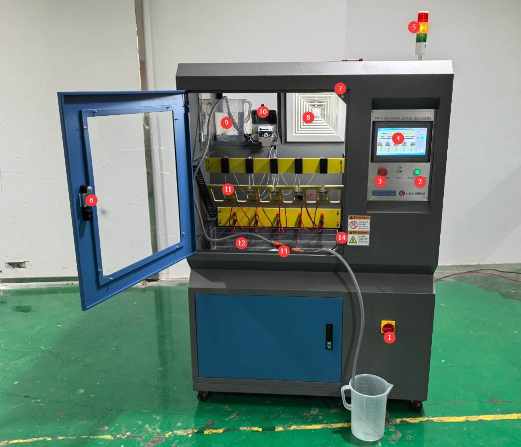
3.1 Overall Structure of the Equipment
See Figure 3-1.
| Number | Note |
|---|---|
| ① | Testers Power Switch |
| ② | Touchscreen Power Switch |
| ③ | Emergency Stop Button |
| ④ | Touchscreen |
| ⑤ | Testers Operating Status Indicator Lights |
| ⑥ | Test Chamber Door |
| ⑦ | Chamber door safety interlock: Testers can only be started once the chamber door is fully closed. |
| ⑧ | Exhaust Fan |
| ⑨ | Test Solution Bucket |
| ⑩ | Peristaltic pump, used to pump the test solution into the sample station at a standard flow rate |
| ⑪ | Specimen mounting stations: 5 stations that can operate independently without interfering with one another |
| ⑫ | Waste Liquid Tank |
| ⑬ | Small pump: When the solution in the test solution tank needs to be replenished, external solution can be pumped into the solution tank inside the test chamber. |
| ⑭ | Connect the small water pump’s power cord to the terminal block inside the test chamber. |
3.2 Introduction to the Program Interface
3.2.1 Initial Screen
See Figure 3-2.
| Number | Note |
|---|---|
| ① | The selection of the test voltage is similar: AC or DC |
| ② | Select a test method: constant voltage method or step voltage method |
| ③ | Click to go to the Testers interface |
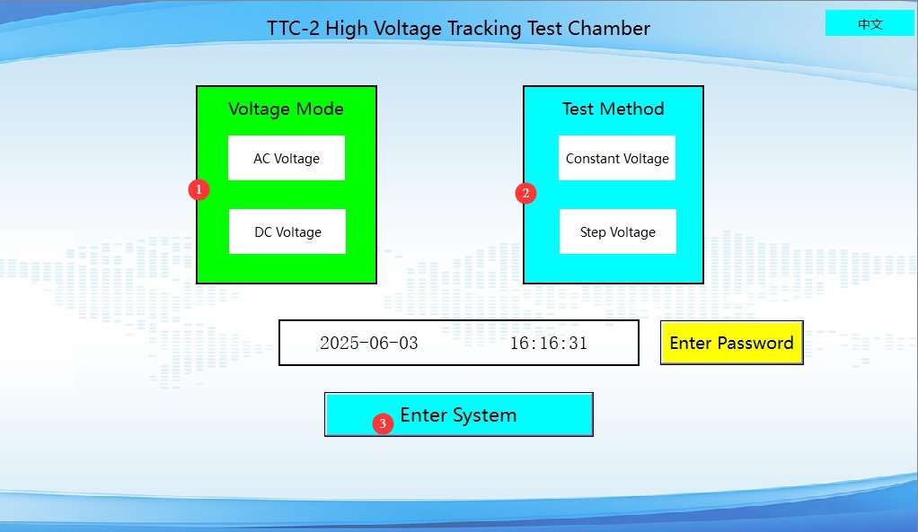
Note: Selected items are displayed in red.
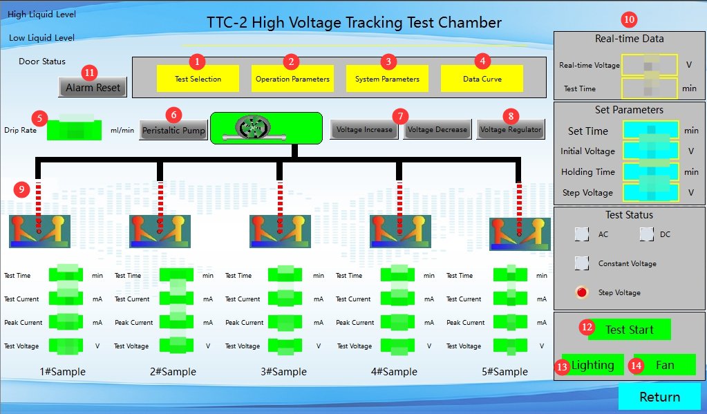
3.2.2 Testers Interface
See Figure 3-3.
| Number | Note |
|---|---|
| ① | Test Mode Selection |
| ② | Operating Parameter Settings |
| ③ | System Parameter Settings |
| ④ | View Testers Curves |
| ⑤ | The peristaltic pump’s dispensing rate is factory-calibrated to the standard flow rate specified by national standards. Do not alter this setting arbitrarily for routine testing. You can view the corresponding setting value in the system parameter settings interface. |
| ⑥ | Peristaltic Pump Switch: Click to turn the peristaltic pump on or off |
| ⑦ | Manual step-up/step-down; generally requires no action |
| ⑧ | Voltage Regulator Switch: Click to turn the Voltage Regulator on or off |
| ⑨ | Display the test data for the 5 specimens separately |
| ⑩ | Display real-time data and configured data |
| ⑪ | Clear Alarms: If an alarm occurs at a specific workstation, that workstation will automatically stop operating without the need to click “Clear Alarms”; when all workstations trigger alarms, you can click “Clear Alarms,” and the equipment will clear the alarms and stop the test. |
| ⑫ | Start/Stop Test |
| ⑬ | Turn the lighting inside the test chamber on/off |
| ⑭ | Turn the exhaust fan on/off. Note: Do not turn it on during the test; turn it on after the test is complete to vent the smoke. |
3.2.3 Test Mode Selection Interface
The Test Mode Selection screen functions identically to the initial screen; see Section 3.2.1.
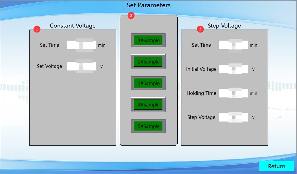
3.2.4 Operating Parameter Settings Interface
See Figures 3–4.
| Number | Note |
|---|---|
| ① | Constant Voltage Method Parameter Settings. Test Duration and Test Voltage Settings |
| ② | Sample Station Selection: Selected stations are highlighted in red; unselected stations will not be tested. |
| ③ | Parameter Settings for the Step-by-Step Voltage Method. Test duration, initial voltage setting, holding time, step-by-step voltage |
3.2.5 System Parameter Settings Interface
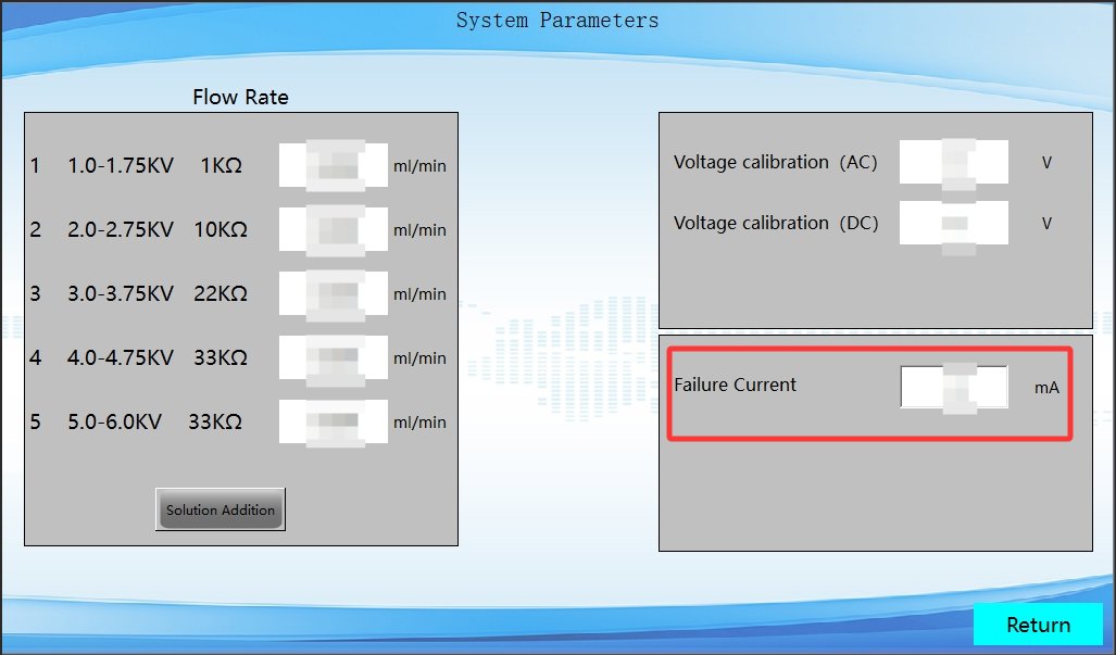
See Figures 3–5. A failure current threshold can be set; that is, if the current value at a particular station reaches the failure current value during the test, the specimen fails, the equipment triggers an alarm, and that station stops operating.
4. Procedure for the High-Voltage Tracking Test
4.1 Preparation of Test Reagents and Consumables
4.1.1 Requirements for the Preparation of Test Solutions
Prepare the test solution in accordance with the applicable standard (using GB/T 6553-2024/IEC 60587:2022 as an example):
Use a contaminant with a conductivity of (0.25–0.25641) S/m at 23 °C ± 1 °C, equivalent to a mass fraction of 0.1% ammonium chloride (NH₄Cl); Refer to Section 3.1: Pour the prepared solution into the test solution bucket and place it in the corresponding position; then, place the peristaltic pump’s feed tube into the solution in the bucket.
4.1.2 Preparation of Filter Paper and Auxiliary Consumables
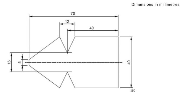
Stack the 8 standard test filter papers (0.2 mm ± 0.02 mm thick) supplied as standard and cut them using the provided 304 stainless steel template to prevent cutting errors from affecting the liquid flow rate; see Figure 4-1 (taken from IEC 60587:2022, Figure 7).
4.2 Sample Preparation and Installation
4.2.1 Sample Preparation
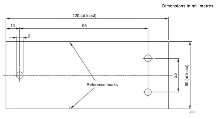
The test specimen dimensions must comply with the requirements of the applicable standard; see Figure 4-2 (taken from IEC 60587:2022, Figure 1). The surface must be smooth and free of defects.
Before the test, wipe the test specimen clean to remove surface oil and dust, and allow it to reach thermal equilibrium under standard conditions;
Prepare five identical test specimens for each test group to conduct parallel Testers and ensure the accuracy of the test results.
4.2.2 Specimen Installation
Verify that the equipment is shut down and powered off, then open the test chamber door.
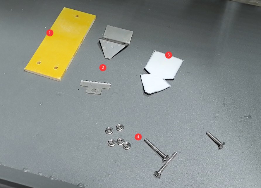
All components are ready, as shown in Figure 4-3.
| Number | Note |
|---|---|
| ① | Test specimens prepared in accordance with the standard |
| ② | Standard Electrodes |
| ③ | Filter paper cut to standard size |
| ④ | Screws for securing the electrode and the specimen |
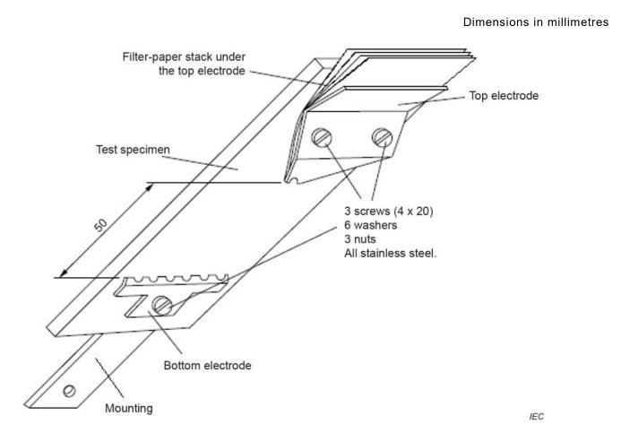
See Figure 4-4 (taken from IEC 60587:2022, Figure 4) for a schematic diagram of the installation standard.
See Figures 4–5 for the actual installation results.
| Number | Note |
|---|---|
| ① | Test specimen |
| ② | A stack of filter paper beneath the upper electrode |
| ③ | Upper electrode |
| ④ | Lower electrode |
| ⑤ | At the contaminant inlet, press the dropper tubing for the corresponding workstation firmly against the back of the filter paper stack. |
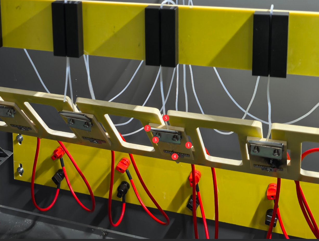
Check the installation status of the test specimens at each of the five stations one by one, and close the test chamber door after confirming that everything is in order.
4.3 Test Procedure
| Instructions | Note |
|---|---|
| ① | Refer to the standards and configure all parameters |
| ② | Start the peristaltic pump |
| ③ | Once the contaminant has flowed normally onto the surface of the test specimen, begin the test. |
| ④ | Observe and record test phenomena, such as smoke, sparks, and the development of electrical tracking; if the leakage current at a particular test station reaches the preset value, the equipment will sound an alarm and halt Testers that station, while Testers continues at other stations; if a fire breaks out, the test must be manually terminated to prevent Testers. |
| ⑤ | After the test is complete, turn on the fan to vent the smoke. |
4.4 End of the Test
4.4.1 Power-Off Procedures
Verify that all channel tests have been completed, the high voltage has been fully reduced to zero, and the equipment is in standby mode; turn off the equipment’s control power; trip the circuit breaker in the power supply circuit to cut off the equipment’s main power supply.
4.4.2 Specifications for Specimen Removal
After confirming that the equipment is powered off and the high voltage has been reduced to zero, open the test chamber door; use tweezers or insulated tools to remove the test specimens one by one, taking care not to touch the electrodes to prevent residual charge; place the test specimens on the dedicated specimen tray, and observe their condition after they have cooled to room temperature.
4.4.3 Determination of Arc Marks and Erosion Severity
Rate the test specimens according to the requirements of the applicable standard: Observe the length and width of the electrical tracks on the specimen’s surface and determine whether they extend all the way through to both electrodes; measure the depth and area of the erosion on the specimen to assess the extent of the erosion; combine this with the leakage current data and failure time recorded during the test to draw test conclusions; Based on a comprehensive evaluation of the results from the five test specimens, determine the material’s resistance to tracking and erosion.
5. Daily Maintenance and Care of Equipment
5.1 Equipment Cleaning and Waste Liquid Disposal After the Test
5.1.1 Cleaning the Test Chamber
After removing the sample and the electrode, use a lint-free cloth to wipe down the sample stage and electrode holder to remove any residual solution and sample debris; wipe down the dropper tubing to prevent residual solution from crystallizing and causing a blockage; Check the electrode surface for burn marks or stains; if necessary, gently sand and clean it with 800-grit or finer sandpaper.
5.1.2 Treatment of Waste Liquids and Residual Solutions
Empty all experimental waste liquid from the waste liquid tank into a dedicated waste liquid collection container and dispose of it in accordance with hazardous waste regulations; if there is a significant amount of solution remaining in the solution container and it has not deteriorated, it may be sealed and stored; if it is contaminated or has deteriorated, it should be treated as waste liquid; Use deionized water to rinse the solution tank, waste liquid tank, and piping, then drain the rinse water to prevent residual solution from crystallizing and corroding the piping.
5.2 Scheduled Maintenance Items
5.2.1 Monthly Maintenance
Electrode Maintenance: Inspect the electrode surfaces for oxidation and ablation; grind and polish the electrode contact surfaces; measure the electrode spacing and calibrate it. Fluid Path Maintenance: Thoroughly clean the peristaltic pump tubing and dispensing needles; replace any tubing that is aged or damaged. Electrical Inspection: Tighten the electrode terminals and check for any loose connections or overheating.
5.2.2 Quarterly Maintenance
Enclosure Sealing Inspection: Check whether the door gaskets are aged or cracked; replace any defective gaskets to ensure the enclosure is properly sealed; Voltage Transformer Inspection: Check the oil level in oil-immersed voltage transformers, inspect for leaks, and clean the voltage transformer cooling fins; Ventilation and Dust Removal: Remove dust from equipment vents and electrical compartments to ensure proper heat dissipation.
5.2.3 Annual Calibration and Verification
To ensure Testers and reliability of the tester, it is recommended that calibration be performed periodically by a qualified third-party metrology organization. The recommended calibration interval is 12 months. Users may determine the specific calibration interval based on frequency of use, environmental conditions, and quality system requirements.
5.3 Long-Term Storage and Maintenance
5.3.1 Preparations Before Storage
Thoroughly clean the equipment inside and out; drain all liquids from the fluid lines and reservoirs, and dry the lines; remove components such as electrodes, clean them, and store them in separate packaging; apply rust-preventative oil to metal parts to prevent rust during long-term storage; disconnect the power supply, unplug the power cord, and tidy up the cables.
5.3.2 Storage Environment Requirements
The storage environment must be dry, well-ventilated, and free of corrosive gases, with an ambient temperature of 5°C to 40°C and a relative humidity of ≤70%; The equipment must be covered with a dust cover to prevent dust accumulation; power it on and run it for 30 minutes at regular intervals (every 3 months) to remove moisture and protect the electrical components; do not stack heavy objects on the equipment to prevent deformation caused by compression.
6. Troubleshooting and Resolving Common Problems
| Fault Symptoms | Possible Causes | Procedure |
|---|---|---|
| The device won’t turn on | Power supply malfunction; emergency stop button has not been reset | Ensure that the power supply matches the specifications on the nameplate; reset the emergency stop button and try again. |
| Touchscreen Not Responding | System crashes, loose touchscreen cable | Unplug the device, check the cable connected to the back of the touchscreen, then turn it on and try again. |
| Significant voltage fluctuations | Unstable input power supply voltage | It is recommended to use a regulated power supply to power the instrument. |
| Dispensing System Malfunction | The peristaltic pump is not operating, the dispensing rate has been changed, or the dispensing tube is clogged | Make sure the peristaltic pump is turned on; check the drip rate setting; flush the drip tubing with deionized water to clear any blockages. |