English
 中文简体
中文简体 English
 Русский
 Español
 Português
 Türkçe
 العربية
 Deutsch
 Polski
 Italiano
 Français
 한국어
한국어 ไทย
ไทย Tiếng Việt
 日本語
日本語





























Thermally Protected Ballast Heating Test Chamber
User's Manual
Applicable LISUN models: TPB-UL935
1. Basic Understanding of Equipment
1.1 Key Parameters
1.1.1 Equipment Technical Specifications
| Parameters | Note |
|---|---|
| Chamber Dimensions (Length × Width × Height) | 610 mm × 610 mm × 610 mm (Compatible with most ballast specifications; meets the needs of both batch testing and individual sample testing) |
| Temperature Range | RT + 10°C to +100°C (RT stands for room temperature; this covers the typical temperature range for high-temperature adaptability testing of ballasts) |
| Temperature Uniformity | ≤±2°C |
| Temperature fluctuation | ≤±0.5°C |
| Materials of the Inner and Outer Cases | High-grade stainless steel sheet (corrosion-resistant and heat-resistant, preventing chamber aging or rust from affecting test accuracy) |
| Insulation Material | Ultra-fine glass wool insulation (offers excellent thermal insulation, reduces heat transfer between the interior and exterior of the enclosure, and lowers energy consumption) |
| Sample Rack Configuration | Specialized wooden test specimen rack (offers excellent insulation, prevents thermal interference from metal racks, and accommodates ballasts of various sizes) |
| Heater Types | Special-purpose bar heaters (dimensions: 300 mm × 40 mm; power per set: 300 W) |
| Number of Heaters and Connection Methods | There are 4 sets in total, connected in parallel (for faster heating; a failure in a single set does not affect the overall test, thereby enhancing equipment reliability). |
| Temperature Measurement Points | Three temperature measurement points (switchable at any time between measurement and control to meet temperature monitoring needs at different locations, such as the sample surface or the interior of the chamber) |
| Temperature Control Method | Intelligent PID Temperature Control System (automatically adjusts heating power to precisely maintain the set temperature) |
| Safety and Security | Over-temperature protection (automatically cuts off the heating power when the temperature exceeds the set upper limit), overload protection (prevents safety issues caused by heater malfunctions) |
| Observation and Operation | Equipped with a high-temperature-resistant glass viewing window (for real-time observation of sample conditions) and a touchscreen control panel (for convenient temperature setting and data reading) |
1.1.2 Applicable Standards
| Standard Number | Standard Title |
|---|---|
| GB 19510.1-2023 | Control Devices for Lamps—Part 1: General and Safety Requirements |
| IEC 61347-1:2024 | Lamp Control Gear – Part 1: General and Safety Requirements |
| UL 935:2007 | Standard for Fluorescent Lamp Ballasts (with Class P Thermal Protection) |
1.2 Application Scenarios
The TPB-UL935 Thermally Protected Ballast Heating Test Chamber is a high-temperature environmental simulation device specifically designed for electronic and electrical components such as lamp ballasts. It uses a precise and controllable temperature environment to verify the thermal protection performance and high-temperature adaptability of thermally protected ballasts.
It can be used for random inspections of thermal protection functions in ballasts prior to shipment, high-temperature performance optimization testing during the R& D phase, high-temperature environmental testing for product compliance certification, and type testing and reliability verification by quality control departments.
1.3 Equipment Configuration Verification
1.3.1 Unpacking
When unpacking the device, handle it gently to avoid scratching the outer casing with sharp tools. After unpacking, first inspect the exterior of the device to ensure there are no obvious deformities or dents, and that the buttons are not damaged or loose. If you notice any abnormalities with the device or its accessories, do not turn it on. Please contact us immediately.
1.3.2 Host Computer and Accessories
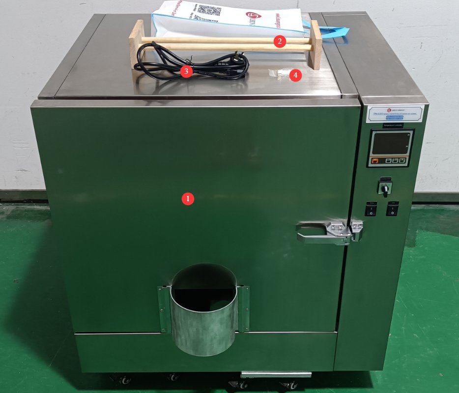
See Figure 1-1.
| Number | Note |
|---|---|
| ① | TPB-UL935 Main Unit |
| ② | Specialized Wooden Sample Rack |
| ③ | Power Cord |
| ④ | Spare Fuses |
2. Precautions for Use
2.1 General Safety Operating Guidelines
Personnel Requirements
Operators must undergo training based on this manual and become familiar with the equipment’s operating procedures before being allowed to operate it; a designated person must be on duty during testing, and prolonged unattended operation is strictly prohibited; non-professionals must not disassemble the equipment or modify its internal parameters without authorization.
General Prohibitions
It is strictly prohibited to place flammable, explosive, or corrosive samples inside the chamber for testing; it is strictly prohibited to store flammable materials near the equipment; it is strictly prohibited to rinse the interior of the equipment directly with water; and it is strictly prohibited to force the chamber door open while the equipment is in operation.
Emergency Response
If you notice unusual smoke or odors, immediately turn off the main power supply; if you suffer a burn, immediately rinse the affected area with cold water for at least 15 minutes, and seek medical attention for severe burns; if an electrical malfunction occurs, turn off the power before troubleshooting—never perform repairs while the equipment is energized.
2.2 Electrical Safety Precautions
The equipment must be connected to a dedicated power circuit rated at 220 V AC ±10%, 50/60 Hz; the power supply must be reliably grounded, with a grounding resistance of ≤0.5 Ω; the power cord cross-sectional area must be at least 2.5 mm²; and the outlet must have a rated current of ≥10 A.
2.3 Precautions for High-Temperature Operations
Sample Collection and Return
When opening the chamber door while it is hot, wear heat-resistant gloves; when opening the door, turn your body away from the front to avoid being hit by hot air and suffering burns; use the designated tongs to remove samples—never touch hot samples with your bare hands.
Temperature Limits
The maximum operating temperature of the equipment is 100°C; operating the equipment at temperatures exceeding this limit is strictly prohibited. Allow for a margin when setting the temperature to avoid triggering the over-temperature protection. Continuous operation at high temperatures should not exceed 72 hours.
2.4 Precautions for Sample Placement
Display Guidelines
Samples must be placed on a dedicated wooden sample rack and must not come into direct contact with the bottom of the chamber; a gap of at least 50 mm must be maintained between samples to ensure air circulation; samples must not obstruct the temperature sensor.
Weight Limit
The sample holder has a maximum load capacity of 10 kg; do not place overweight or sharp samples on it; the sample’s center of gravity must be centered to prevent the sample holder from tilting.
3. Equipment Overview
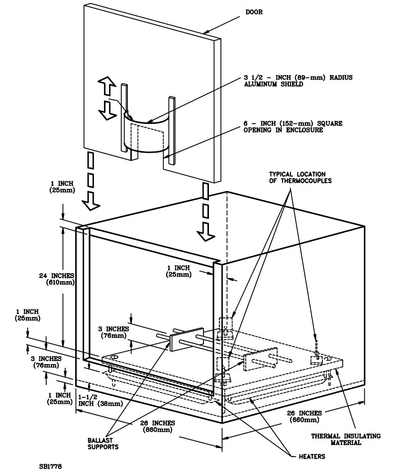
3.1 Standard Diagram
See Figure 3-1 (taken from UL 935, Figure 25.1).
3.2 Product Photos
3.2.1 Exterior Structure and Functions of the Enclosure
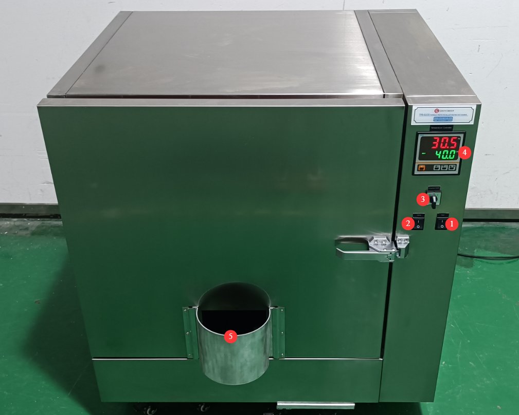
See Figure 3-2.
| Number | Note |
|---|---|
| ① | Power Switch |
| ② | Heating switch; when turned on, the heating function is activated. |
| ③ | Temperature Selector Switch: Switches between the three thermocouples (0, 1, 2) inside the test chamber |
| ④ | Temperature control instrument used to set and display the current thermocouple temperature |
| ⑤ | Aluminum cover with a square opening; the aluminum cover can be moved up and down |
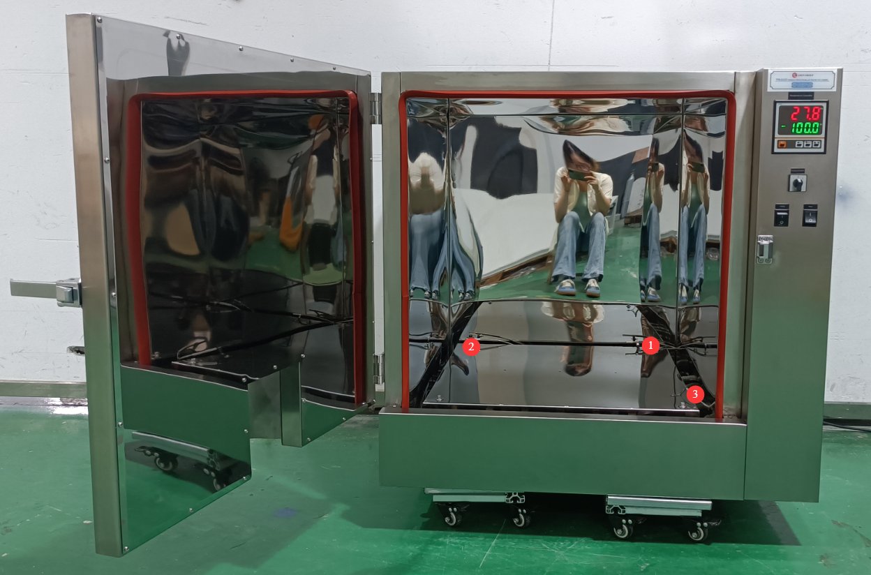
3.2.2 Internal Structure of the Enclosure
See Figure 3-3.
| Number | Note |
|---|---|
| ① | Type 0 Thermocouple |
| ② | Type 1 Thermocouple |
| ③ | Type 2 Thermocouple |
3.2.3 Use of Temperature Control Instruments
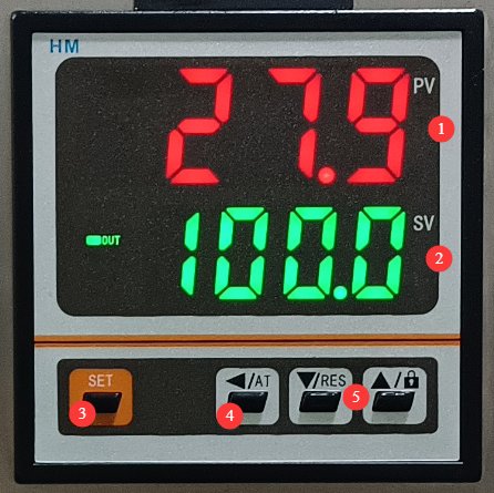
See Figures 3–4.
| Number | Note |
|---|---|
| ① | The top line displays the current temperature in °C. |
| ② | The lower display shows the set temperature in °C. |
| Steps for Setting the Temperature: | |
| ③ | Press the Settings button |
| ④ | Move the cursor |
| ⑤ | Use the up and down arrows to adjust the number, then press the Set button again to confirm and exit the settings. |
4. Daily Maintenance and Care of Equipment
4.1 Routine Cleaning and Maintenance
4.1.1 Cleaning the Exterior of the Enclosure
Cleaning Frequency: Once a week
Cleaning Instructions: Wipe the exterior of the unit with a clean, soft cloth dampened with a neutral detergent.
Precautions: Do not use strong acids or strong alkalis as cleaning agents; do not scratch the surface with hard objects such as steel wool, as this may damage the stainless steel surface; use a dry, soft cloth to clean the control panel to prevent liquids from seeping in; disconnect the power before cleaning.
4.1.2 Cleaning the Interior of the Chamber
Cleaning Schedule: Remove debris after each test; perform a deep cleaning once a month.
Cleaning Instructions: Wait until the chamber has cooled completely before cleaning. Wipe dust from the interior walls and the surface of the thermocouple with a dry cloth. If there are stains, gently wipe them with a damp cloth dipped in a neutral detergent. After cleaning, open the chamber door to allow it to air out and dry.
Important Notes: Do not rinse the interior directly with water; gently wipe the surface of the temperature sensor to prevent it from shifting.
4.2 Inspect the seals regularly
Inspection Frequency: Once every 6 months
Inspection Items: Check the door gaskets for signs of aging, cracking, or warping; check whether the gaskets retain good elasticity.
Solution: For minor dirt, clean with warm water and wipe dry; if the seal is worn out or defective, contact customer service to replace it with a seal of the same model.
4.3 Long-Term Storage and Maintenance
Preparation Before Storage
Thoroughly clean the inside and outside of the case and let it dry completely; remove the wooden sample rack and store it separately in a dry place; check that all parts are in good condition and apply rust-proofing treatment.
Storage Environment Requirements
Ambient temperature: -10°C to +40°C; Relative humidity: ≤80%, no condensation; Storage location: Well-ventilated, dry, and free of corrosive gases; Stacking requirements: Do not stack heavy objects on top of the equipment; Regular inspection: Power on the equipment once every 3 months and run it for 30 minutes to remove moisture.
4.4 Calibration Interval Requirements
To ensure the measurement accuracy and operational reliability of the equipment, it is recommended that it be sent periodically to a qualified third-party metrology laboratory for calibration. The recommended calibration interval is 12 months. Users may determine the specific calibration interval based on usage frequency, environmental conditions, and quality system requirements.
5. Troubleshooting and Resolving Common Problems
| Number | Note |
|---|---|
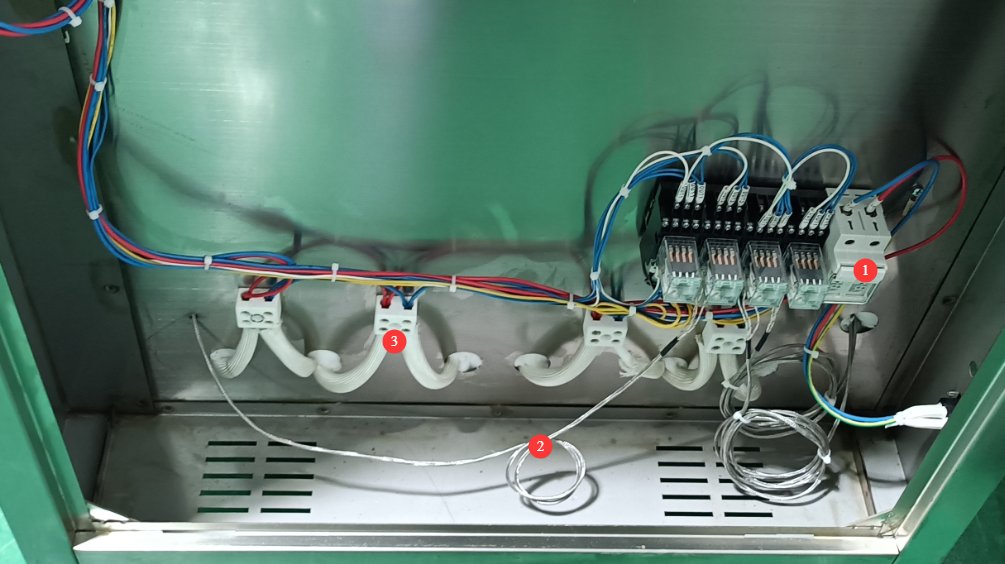
| ① | Fuse Location: If the test chamber won’t turn on, check the fuse. |
| ② | Thermocouple connection wires: If the temperature reading is abnormal, check and confirm that all connections are secure. |
| ③ | Heater Wiring. If the heater is open-circuited, heating performance will be reduced; if the heater is short-circuited to the equipment housing, it may cause the fuse to blow. With the power off, use a multimeter to check the heater’s resistance (normally around 160 Ω) and whether there is a short circuit to the housing. |