
LM-79 Moving Detector Goniophotometer (Mirror Type C)
LSG-6000

High Precision Rotation Luminaire Goniophotometer
LSG-1890B

High Precision Rotation Luminaire Goniospectroradiometer
LSG-1890BCCD

Goniophotometer for Automotive and Signal Lamps
LSG-1950

Goniophotometer for Traffic Signal Lamps (Economical Model)
LSG-1950S
Goniophotometer for Airfield Lighting
LSG-1940

VAD Fire Alarm Visual Alert Device Goniophotometer
LSG-1930

Compact Goniophotometer
LSG-1200A

LED Goniophotometer
LSG-1100
Near Field Moving Detector Goniophotometer
LSG-1900B
 LEDs and Luminaire Test Solutions
 LM-79 and LM-80 Test Solutions
 LED Driver Test Solutions
 Household Appliances Test Solutions
 Mobile and Network Test Solutions
 Automotive Electronics Test Solutions
 Audio-Video and IT Test Solutions
 Cable and Wire Test Solutions
 Plugs and Sockets Test Solutions
 Power Switch Test Solutions
 Transformer Test Solutions
 Electric Toys Test Solutions
 Energy Meter Test Solutions
 Motor-Operated Tool Test Solutions
Select an organization
to browse standards
Product No: GNGPL-31T31
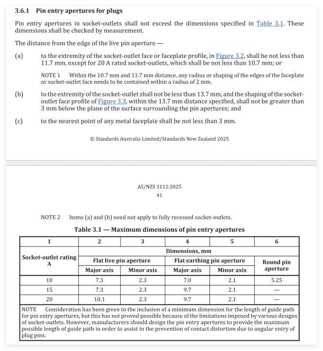
GNGPL-31T31 Pin Entry Aperture Gauge Set complies strictly with AS/NZS 3112:2025 Clause 3.6.1 and Table 3.1. This set of gauges is used to verify that the pin entry apertures of socket-outlets do not exceed the maximum permitted dimensions defined in the standard. AS/NZS 3112:2025 Clause 3.6. also defines critical clearance requirements from live pin aperture edges to the socket face profile and metal faceplate: the distance from the live pin aperture extremity to the socket face profile shall meet specified minimum values, and the distance to any metal faceplate must be no less than 3 mm. Note that requirements (a) and (b) are exempt for fully recessed socket-outlets.
Table 3.1 specifies different maximum aperture dimensions for 10 A, 15 A and 20 A rated sockets, covering flat live pin apertures, flat earthing pin apertures and round pin apertures.
Specifications:
• Applicable Standard: AS/NZS 3112:2025 Clause 3.6.1, Table 3.1
• Gauges Included (Maximum aperture dimension probes):
10 A socket: Flat live pin (7.3 mm × 2.3 mm); Flat earth pin (7.0 mm × 2.1 mm)
15 A socket: Flat live pin (7.3 mm × 2.3 mm); Flat earth pin (9.7 mm × 2.1 mm)
20 A socket: Flat live pin (10.1 mm × 2.3 mm); Flat earth pin (9.7 mm × 2.1 mm)
• Round pin aperture gauge: 5.25 mm diameter (for 10 A round pin socket-outlets)
• Material: High-hardness tool steel, precision CNC machined, anti-rust surface treatment
• Test Principle: The gauge represents the maximum allowable size of pin entry aperture; if the gauge can fully enter the aperture, the socket fails the test.
• Clearance Rules from Standard:
Minimum distance from live pin aperture extremity to face profile: 11.7 mm (10 A /15 A), 10.7 mm (20 A)
Minimum distance from aperture extremity to metal faceplate: ≥ 3 mm
Test Procedures:
• Carry out dimensional measurement on each pin entry aperture of the socket-outlet and check against the maximum dimensions listed in Table 3.1.
• Verify the distance from the extremity of each live pin aperture to the socket-outlet face or faceplate profile to ensure it meets the required minimum value.
• Check the shaping of the socket-outlet face profile within the specified distance range and confirm it does not exceed the permitted recess depth.
• Measure the distance from each pin aperture to the nearest point of any metal faceplate to ensure the distance is not less than 3 mm.
• For fully recessed socket-outlets, the distance requirements in item (a) and item (b) do not need to be implemented.
• Manufacturers are recommended to design pin entry apertures with the longest practical guide path to reduce contact distortion caused by angled plug insertion.
Applications:
• Dimensional inspection of pin entry apertures for Australian and New Zealand socket-outlets per AS/NZS 3112:2025 Clause 3.6.1
• Pre-compliance testing before SAA certification application
• Incoming quality control and finished product inspection for socket manufacturers
• Verification of surface clearance distances between pin apertures and metal faceplates
• Test equipment for third-party electrical safety laboratories
• R&D validation during new socket-outlet mould design
AS/NZS 3112:2025 Clause 3.6.1 Table 3.1

 English
 中文简体
中文简体 English
 Русский
 Español
 Português
 Türkçe
 العربية
 Deutsch
 Polski
 Italiano
 Français
 한국어
한국어 ไทย
ไทย Tiếng Việt
 日本語
日本語






