
LM-79 Moving Detector Goniophotometer (Mirror Type C)
LSG-6000

High Precision Rotation Luminaire Goniophotometer
LSG-1890B

High Precision Rotation Luminaire Goniospectroradiometer
LSG-1890BCCD

Goniophotometer for Automotive and Signal Lamps
LSG-1950

Goniophotometer for Traffic Signal Lamps (Economical Model)
LSG-1950S
Goniophotometer for Airfield Lighting
LSG-1940

VAD Fire Alarm Visual Alert Device Goniophotometer
LSG-1930

Compact Goniophotometer
LSG-1200A

LED Goniophotometer
LSG-1100
Near Field Moving Detector Goniophotometer
LSG-1900B
 LEDs and Luminaire Test Solutions
 LM-79 and LM-80 Test Solutions
 LED Driver Test Solutions
 Household Appliances Test Solutions
 Mobile and Network Test Solutions
 Automotive Electronics Test Solutions
 Audio-Video and IT Test Solutions
 Cable and Wire Test Solutions
 Plugs and Sockets Test Solutions
 Power Switch Test Solutions
 Transformer Test Solutions
 Electric Toys Test Solutions
 Energy Meter Test Solutions
 Motor-Operated Tool Test Solutions
Select an organization
to browse standards
Product No: GNGPL-3121
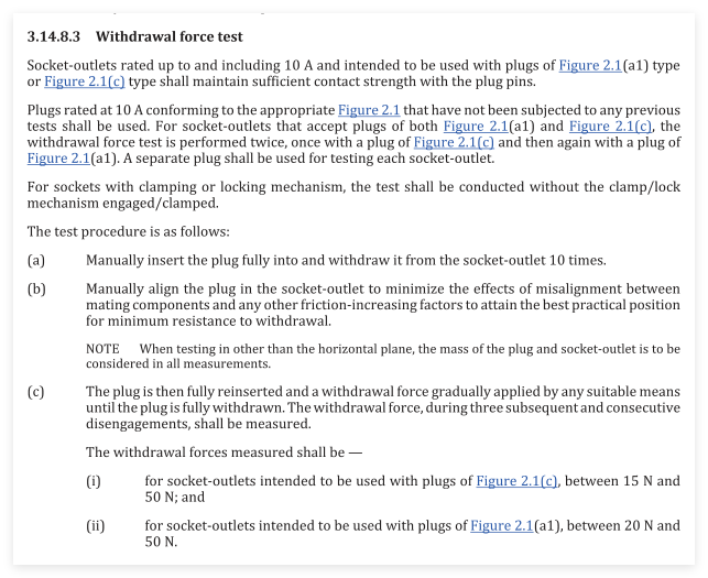
GNGPL-3121 Withdrawal Force Test Plug Set strictly complies with AS/NZS 3112:2025 Clause 3.14.8.3. Figure 2.1 in AS/NZS 3112:2025 defines multiple Australian standard plug types:
• Figure 2.1(a1)/(a2): Three-pin flat pin plugs (10A/15A/20A, 250 V max)
• Figure 2.1(b): Two-pin flat pin plug (10 A, 125 V max)
• Figure 2.1(c): Two-pin flat pin plug (up to 10 A, 250 V max)
• Figure 2.1(d): Side-entry plugs (up to 15 A, 250 V max)
• Figure 2.1(e): Shape restrictions for plug housings and projections
• Figure 2.1(f)/(g): Three-pin plugs with round earth pin or round active pins
Clause 3.14.8.3 withdrawal force test only applies to socket-outlets rated up to 10 A designed for Figure 2.1(a1) three-pin plugs and/or Figure 2.1(c) two-pin plugs. This test plug set contains Figure 2.1(a1) and Figure 2.1(c) test plugs to verify whether sockets maintain sufficient contact retention force with plug pins. Separate test plugs must be used for each socket sample. For universal sockets accepting both plug styles, testing shall be carried out twice with both plug models. For sockets fitted with clamping or locking mechanisms, the lock structure shall remain disengaged during testing.
Specifications:
• Applicable Standard: AS/NZS 3112:2025 Clause 3.14.8.3, Figure 2.1 series drawings
• Supplied Test Plugs for Withdrawal Force Test:
Figure 2.1(a1): 10 A three flat-pin plug (250 V max)
Figure 2.1(c): Up to 10 A two flat-pin plug (250 V max)
• Manufacturing Material: High-hardness tool steel, precision CNC machined, anti-corrosion surface finishing
• Mandatory Withdrawal Force Acceptance Range:
Sockets for Figure 2.1(c) two-pin plugs: 15 N ~ 50 N
Sockets for Figure 2.1(a1) three-pin plugs: 20 N ~ 50 N
Important Note: Figure 2.1(a2), (b), (d), (e), (f), (g) plug formats are defined in the standard but not covered within the scope of Clause 3.14.8.3 withdrawal force test. Corresponding test plugs for these types can be ordered separately on request.
Test Procedures
• Manually insert the plug fully into the socket-outlet and withdraw it for 10 cycles.
• Align the plug inside the socket manually to minimize misalignment and extra friction to achieve the practical optimum position for minimum withdrawal resistance.
• Fully reinsert the plug, then gradually apply withdrawal force via suitable equipment until the plug is completely separated from the socket.
• Conduct three continuous disengagement tests and record each withdrawal force reading.
• When the socket accepts both Figure 2.1(a1) and Figure 2.1(c) plugs, complete the full test sequence firstly using Figure 2.1(c) plug and repeat all steps again with Figure 2.1(a1) plug.
• If testing is performed in non-horizontal orientation, the mass of plug and socket must be taken into account during all force measurements.
Applications:
• Withdrawal force compliance testing for Australian & New Zealand 10 A socket-outlets following AS/NZS 3112 Clause 3.14.8.3
• Pre-compliance testing prior to SAA safety certification submission
• Incoming quality inspection and mass production quality control for socket manufacturers
• Contact retention force verification in third-party electrical testing laboratories
• R&D performance validation for new universal socket-outlets compatible with Figure 2.1(a1) and Figure 2.1(c) plugs
• Standard reference fixture for researching compatibility with full Figure 2.1 series Australian plugs
AS/NZS 3112:2025 Clause 3.14.8.3

 English
 中文简体
中文简体 English
 Русский
 Español
 Português
 Türkçe
 العربية
 Deutsch
 Polski
 Italiano
 Français
 한국어
한국어 ไทย
ไทย Tiếng Việt
 日本語
日本語






