LM-79 Moving Detector Goniophotometer (Mirror Type C)
LSG-6000

High Precision Rotation Luminaire Goniophotometer
LSG-1890B

High Precision Rotation Luminaire Goniospectroradiometer
LSG-1890BCCD

Goniophotometer for Automotive and Signal Lamps
LSG-1950

Goniophotometer for Traffic Signal Lamps
LSG-1950S

Compact Goniophotometer
LSG-1200A

Near Field Moving Detector Goniophotometer
LSG-1900B
Select an organization
to browse standards
If interference exists, or if uncertain of the existence of interference between the contact and the thermoplastic or resilient moulding, the withdrawal force test is conducted on each socket contact where the assembly is modified by removing the suspected interfering material from around the contact, or an independent contact is removed from the assembly.
The withdrawal force of each socket contact shall be measured by a test pin gauge of Figure 3.10.
The withdrawal force shall be not less than 1.5 N for ratings up to and including 10 A, 2 N for ratings above 10 A up to and including 15 A and 3 N for ratings above 15 A.
NOTE: The submitter may provide additional un-assembled contacts for the purpose of this test where required.
In socket-outlets designed for use with plugs complying with Figure 2.1, the contacts shall be self-adjusting in pitch and contact making.
Socket-outlets rated up to and including 10 A, and intended to be used with plugs of the Figure 2.1(al) type or Figure 2.1(c) type, shall withstand the lateral strain imposed by equipment likely to be introduced into them.
Socket-outlets for use with plugs of the Figure 2.1(al) type shall be tested by the application of the gauge shown in Figure 3.6 and Figure 3.7, and socket-outlets for use only with plugs of the Figure 2.1(c) type shall be tested by the application of the gauge shown in Figure 3.7 as follows:
(a)Application oftest gauges The gauge shown in Figure 3.6 shall be applied to three socket-outlets not subjected to any previous test of this Standard. The gauge shown in Figure 3.7 shall be applied to three socket-outlets not subjected to any previous test of this Standard.
(b)Test procedure Each specimen shall be mounted on a vertical surface with the plane through the socket contacts horizontal. The gauge shall be then fully engaged and a weight hung on it such that the force exerted is 5 N.
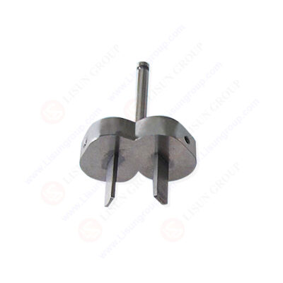
 of AS/NZS 3112 Figure 3.7 3")
Device for Checking The Resistance to Lateral Strain (Two-Pin Gauge) of AS/NZS 3112 Figure 3.7
The gauge shall be removed after 1 min and the socket-outlet shall be turned through 90°on the mounting surface. The test shall be made once in each of the following positions: 0°.90°,180°and 270°.
During the test, the gauge shall not come out.
After the tests, the socket-outlets shall show no damage within the meaning of this Standard and, in particular,socket-outlets intended for use with plugs of the type shown in Figure 2.1(al) shall comply with the requirements of Clause 3.14.8.3.
In addition the withdrawal force of each socket contact that has been subjected to the above tests shall be measured by a test pin gauge of Figure 3.10. The withdrawal force shall be not less than 1.5 N.
Shutters, if any, shall be rendered inoperative so as not to affect the test.
Tags:GNGPL-3137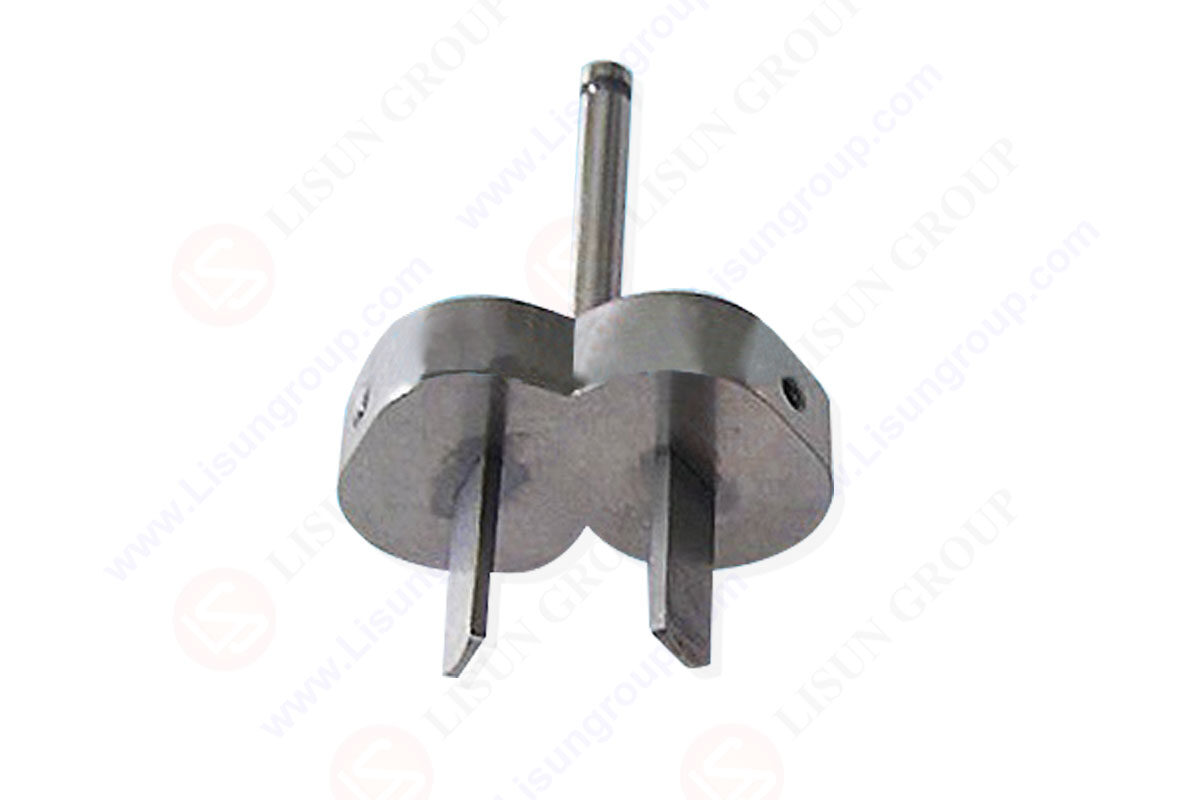

 中文简体
中文简体