
LM-79 Moving Detector Goniophotometer (Mirror Type C)
LSG-6000

High Precision Rotation Luminaire Goniophotometer
LSG-1890B

High Precision Rotation Luminaire Goniospectroradiometer
LSG-1890BCCD

Goniophotometer for Automotive and Signal Lamps
LSG-1950

Goniophotometer for Traffic Signal Lamps
LSG-1950S

Compact Goniophotometer
LSG-1200A

Near Field Moving Detector Goniophotometer
LSG-1900B
Select an organization
to browse standards
Abstract
Impedance characteristics are critical to evaluating the performance of electronic components such as ferroelectric crystals, piezoelectric ceramics, piezoelectric crystals, and ultrasonic transducers. The impedance analyzer circuit, as the core functional unit of an impedance analyzer, determines the accuracy, stability, and efficiency of impedance measurement. This paper takes the LISUN LS90 series impedance analyzer as the research object, systematically expounds the composition and working principle of its impedance analyzer circuit, and deeply explores the application of the instrument in the impedance analysis and testing of ferroelectric crystals, piezoelectric ceramics, piezoelectric crystals, and ultrasonic transducers. Through specific test data and comparative analysis, the performance advantages of the LISUN LS90 impedance analyzer in terms of measurement accuracy, frequency range, and stability are verified. The research results show that the impedance analyzer circuit of the LISUN LS90 series, with its automatic balance bridge technology and four-terminal pair Kelvin test terminal design, can effectively meet the high-precision impedance testing needs of related devices in both laboratory research and production line quality control scenarios, providing reliable technical support for the development and application of piezoelectric and ferroelectric devices.
Keywords
Impedance analyzer circuit; LISUN LS90 Impedance analyzer; Ferroelectric crystals; Piezoelectric ceramics; Piezoelectric crystals; Ultrasonic transducers; Impedance measurement
1. Introduction
In the field of electronic materials and components, ferroelectric crystals, piezoelectric ceramics, piezoelectric crystals, and ultrasonic transducers are widely used in sensors, actuators, filters, and medical imaging equipment. The impedance parameters of these devices, such as resistance (R), reactance (X), impedance (Z), phase angle (θ), admittance (Y), conductance (G), and susceptance (B), directly reflect their electrical properties and working states. For example, the impedance-frequency characteristics of piezoelectric ceramics determine the resonance frequency and bandwidth of piezoelectric sensors, while the impedance stability of ultrasonic transducers affects the efficiency of energy conversion in ultrasonic cleaning and medical diagnosis equipment.
The impedance analyzer is a key instrument for measuring the impedance parameters of electronic components, and the impedance analyzer circuit is the core part that realizes the impedance measurement function. A high-performance impedance analyzer circuit can accurately excite the device under test (DUT) with a stable signal, collect the response signal of the DUT, and calculate the impedance parameters through signal processing and data analysis. The LISUN LS90 series impedance analyzer, developed by LISUN Group, is a representative product in the field of impedance measurement. Its impedance analyzer circuit integrates advanced technologies such as automatic balance bridge and vector testing, which can provide high-precision and wide-range impedance measurement solutions for ferroelectric and piezoelectric devices.
This paper first introduces the composition and working principle of the impedance analyzer circuit of the LISUN LS90 series impedance analyzer; then, it details the test methods and steps of using the instrument to perform impedance analysis on ferroelectric crystals, piezoelectric ceramics, piezoelectric crystals, and ultrasonic transducers; finally, through experimental data and performance analysis, the application value of the LISUN LS90 impedance analyzer in related fields is verified.
The impedance analyzer circuit of the LISUN LS90 series is a complex electronic system composed of multiple functional modules, including a signal generation module, a signal excitation module, a signal acquisition module, a signal processing module, a data calculation module, and a human-computer interaction module. The specific composition and functions of each module are shown in Table 1.
| Module Name | Composition | Function |
| Signal Generation Module | Voltage-controlled oscillator (VCO), frequency synthesizer, crystal oscillator | Generate a stable AC excitation signal with adjustable frequency (20Hz~15MHz) and amplitude (up to 1.000V). The frequency accuracy is as high as 1mHz, ensuring the stability of the excitation signal frequency. |
| Signal Excitation Module | Power amplifier, matching network, four-terminal pair Kelvin test terminals | Amplify the excitation signal generated by the signal generation module to meet the test current requirements (minimum 0.01μA) of different DUTs. The four-terminal pair Kelvin test terminals can eliminate the influence of lead resistance and contact resistance on the measurement results, improving measurement accuracy. |
| Signal Acquisition Module | High-precision ADC (Analog-to-Digital Converter), current/voltage sensor | Collect the voltage signal across the DUT and the current signal flowing through the DUT. The high-precision ADC ensures that the collected signal has low noise and high resolution, laying the foundation for accurate impedance calculation. |
| Signal Processing Module | Digital filter, phase-locked loop (PLL), signal conditioning circuit | Filter the collected analog signal to remove noise interference; use the PLL to lock the frequency of the collected signal with the excitation signal, ensuring the accuracy of phase measurement; condition the signal to make it meet the input requirements of the data calculation module. |
| Data Calculation Module | Microcontroller (MCU), digital signal processor (DSP) | Based on the vector testing principle, calculate the impedance parameters (R-X, Z-θ, Y-θ, G-B) of the DUT according to the collected voltage and current signals. The module has a fast calculation speed, which can realize real-time display of test results. |
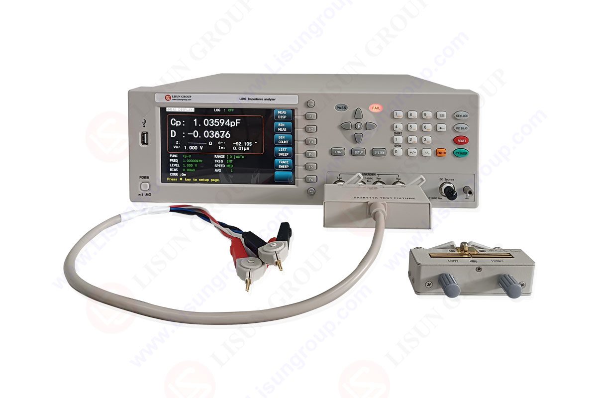
| Human-Computer Interaction Module | 7.0′ TFT-LCD display, operation buttons, communication interface (RS232C, USB DEVICE, GPIB optional) | Display the impedance-frequency scanning curve, test parameters, and instrument status in real time; allow users to set test parameters (such as frequency range, signal amplitude) through operation buttons; support data transmission between the instrument and the computer, facilitating data storage and post-processing. |
The working process of the LISUN LS90 impedance analyzer circuit can be divided into five stages: signal generation, signal excitation, signal acquisition, signal processing, and data calculation and display. The specific working principle is as follows:
• Signal Generation Stage: The crystal oscillator in the signal generation module provides a reference frequency signal with high stability. The frequency synthesizer adjusts the reference frequency according to the user-set frequency range (20Hz~15MHz for the LS90-15M model) to generate a frequency-adjustable signal. The VCO further modulates the signal to generate an AC excitation signal with a stable amplitude (up to 1.000V) and frequency.
• Signal Excitation Stage: The excitation signal generated in the previous stage is amplified by the power amplifier in the signal excitation module to ensure that the test current can meet the requirements of different DUTs (minimum 0.01μA). The matching network adjusts the impedance of the excitation circuit to match the impedance of the DUT, reducing signal reflection and improving the efficiency of energy transmission. Finally, the excitation signal is applied to the DUT through the four-terminal pair Kelvin test terminals. The four-terminal pair design separates the current path and the voltage measurement path, eliminating the influence of lead resistance and contact resistance on the voltage measurement, thereby improving the accuracy of impedance measurement.
• Signal Acquisition Stage: The current/voltage sensor in the signal acquisition module collects the current signal flowing through the DUT and the voltage signal across the DUT respectively. The collected analog signals are sent to the high-precision ADC for analog-to-digital conversion. The ADC has high resolution and low noise, which can accurately convert the analog signals into digital signals for subsequent processing.
• Signal Processing Stage: The digital filter in the signal processing module filters the digital signals to remove noise interference caused by the external environment and the instrument itself. The PLL locks the frequency of the collected signal with the excitation signal, ensuring that the phase difference between the voltage and current signals is measured accurately. The signal conditioning circuit adjusts the amplitude and frequency of the processed signals to make them meet the input requirements of the data calculation module.
• Data Calculation and Display Stage: The DSP in the data calculation module uses the vector testing principle to calculate the impedance parameters of the DUT. Taking the calculation of impedance Z and phase angle θ as an example, the DSP first calculates the amplitude ratio of the voltage signal to the current signal (Z = U/I) and the phase difference between the voltage signal and the current signal (θ = φ_U – φ_I), and then converts them into other impedance parameters (such as R = Zcosθ, X = Zsinθ) according to the user’s needs. The calculated impedance parameters and the impedance-frequency scanning curve are displayed on the 7.0′ TFT-LCD display in real time. At the same time, the instrument can transmit the test data to the computer through the RS232C or USB DEVICE interface for data storage and post-processing.

LS90_AL
The LISUN LS90 series impedance analyzer, relying on its high-performance impedance analyzer circuit, is widely used in the impedance analysis and testing of ferroelectric crystals, piezoelectric ceramics, piezoelectric crystals, and ultrasonic transducers. This section introduces the test methods, steps, and results of the instrument for these four types of devices respectively.
Ferroelectric crystals have a spontaneous polarization phenomenon that can be reversed by an external electric field, and their impedance characteristics are closely related to the polarization state and temperature. The LISUN LS90 impedance analyzer can test the impedance parameters of ferroelectric crystals under different frequencies and temperatures, providing a basis for studying the electrical properties of ferroelectric crystals.
• Instrument: LISUN LS90-10M impedance analyzer (frequency range: 20Hz~10MHz, basic accuracy: 0.05%).
• DUT: Lead zirconate titanate (PZT) ferroelectric crystal (size: 5mm×5mm×1mm).
• Auxiliary Equipment: Temperature-controlled chamber (temperature range: 0℃~40℃), four-terminal pair Kelvin test probes.
• Place the PZT ferroelectric crystal in the temperature-controlled chamber, and set the temperature of the chamber to 25℃ (room temperature).
• Connect the four-terminal pair Kelvin test probes to the test terminals of the LISUN LS90-10M impedance analyzer, and contact the two ends of the PZT ferroelectric crystal with the probes.
• Turn on the impedance analyzer, enter the test parameter setting interface, and set the following parameters:
– Frequency range: 1kHz~10MHz.
– Scan mode: Linear scan (number of scan points: 100).
– Signal amplitude: 0.5V.
– Test parameters: Z-θ (impedance and phase angle).
• Start the test, and the instrument automatically scans the frequency in the set range and collects the impedance and phase angle data of the PZT ferroelectric crystal.
• Adjust the temperature of the temperature-controlled chamber to 30℃, 35℃, and 40℃ respectively, and repeat steps 3-4 to obtain the impedance-frequency characteristics of the PZT ferroelectric crystal at different temperatures.
The impedance-frequency characteristics of the PZT ferroelectric crystal at different temperatures are shown in Table 2. It can be seen from the table that as the temperature increases, the resonance frequency of the PZT ferroelectric crystal decreases slightly, and the impedance at the resonance frequency increases. This is because the increase in temperature leads to an increase in the dielectric loss of the ferroelectric crystal, resulting in a decrease in the resonance frequency and an increase in the impedance. The LISUN LS90-10M impedance analyzer can accurately measure these changes, which is of great significance for studying the temperature stability of ferroelectric crystals.
| Temperature (℃) | Resonance Frequency (MHz) | Impedance at Resonance Frequency (kΩ) | Phase Angle at Resonance Frequency (°) |
| 25 | 5.23 | 1.25 | -1.2 |
| 30 | 5.21 | 1.32 | -1.5 |
| 35 | 5.19 | 1.40 | -1.8 |
| 40 | 5.17 | 1.48 | -2.1 |
Piezoelectric ceramics are a type of functional ceramic material that can convert electrical energy into mechanical energy and vice versa. Their impedance parameters, especially the resonance and anti-resonance frequencies, are important indicators for evaluating their performance. The LISUN LS90 impedance analyzer can quickly and accurately test the resonance and anti-resonance frequencies of piezoelectric ceramics, providing a basis for the production and quality control of piezoelectric ceramic components.
• Instrument: LISUN LS90-15M impedance analyzer (frequency range: 20Hz~15MHz, basic accuracy: 0.05%).
• DUT: Barium titanate (BaTiO₃) piezoelectric ceramic sheet (size: 10mm×10mm×0.5mm).
• Auxiliary Equipment: Four-terminal pair Kelvin test fixture.
• Fix the BaTiO₃ piezoelectric ceramic sheet in the four-terminal pair Kelvin test fixture, and connect the fixture to the test terminals of the LISUN LS90-15M impedance analyzer.
• Turn on the impedance analyzer, enter the test parameter setting interface, and set the following parameters:
– Frequency range: 100kHz~15MHz.
– Scan mode: Logarithmic scan (number of scan points: 200).
– Signal amplitude: 1.0V.
– Test parameters: R-X (resistance and reactance).
• Start the test, and the instrument automatically scans the frequency in the set range and collects the resistance and reactance data of the BaTiO₃ piezoelectric ceramic sheet.
• After the test is completed, the instrument automatically identifies the resonance frequency (f_r) and anti-resonance frequency (f_a) of the piezoelectric ceramic sheet according to the change of reactance (X) with frequency (when X=0, the corresponding frequency is f_r and f_a).
• Repeat the test 5 times to calculate the average value of f_r and f_a, and evaluate the repeatability of the test results.
The test results of the resonance and anti-resonance frequencies of the BaTiO₃ piezoelectric ceramic sheet are shown in Table 3. It can be seen from the table that the repeatability of the test results of the LISUN LS90-15M impedance analyzer is good, and the maximum deviation of the resonance frequency and anti-resonance frequency is less than 0.02MHz. This indicates that the impedance analyzer circuit of the LISUN LS90 series has high stability and can meet the repeatability requirements of piezoelectric ceramic testing in the production line.
| Test Times | Resonance Frequency (f_r, MHz) | Anti-Resonance Frequency (f_a, MHz) | Deviation of f_r (MHz) | Deviation of f_a (MHz) |
| 1 | 8.56 | 10.23 | 0 | 0 |
| 2 | 8.57 | 10.24 | +0.01 | +0.01 |
| 3 | 8.55 | 10.22 | -0.01 | -0.01 |
| 4 | 8.56 | 10.23 | 0 | 0 |
| 5 | 8.57 | 10.24 | +0.01 | +0.01 |
| Average | 8.56 | 10.23 | – | – |
| Maximum Deviation | – | – | ±0.01 | ±0.01 |
Piezoelectric crystals have high frequency stability and are widely used in oscillators and filters. The impedance characteristics of piezoelectric crystals, especially the equivalent series resistance (ESR) and quality factor (Q), directly affect the performance of oscillators and filters. The LISUN LS90 impedance analyzer can accurately test the ESR and Q value of piezoelectric crystals, providing a basis for the selection and application of piezoelectric crystals.
• Instrument: LISUN LS90-10M impedance analyzer (frequency range: 20Hz~10MHz, basic accuracy: 0.05%).
• DUT: Quartz piezoelectric crystal (frequency: 1MHz, package: HC-49U).
• Auxiliary Equipment: Piezoelectric crystal test socket, four-terminal pair Kelvin test wires.
• Insert the quartz piezoelectric crystal into the piezoelectric crystal test socket, and connect the test socket to the test terminals of the LISUN LS90-10M impedance analyzer using four-terminal pair Kelvin test wires.
• Turn on the impedance analyzer, enter the test parameter setting interface, and set the following parameters:
– Frequency: 1MHz (the nominal frequency of the piezoelectric crystal).
– Signal amplitude: 0.1V (to avoid overexcitation of the piezoelectric crystal).
– Test parameters: R-X (resistance and reactance), Q value.
• Start the test, and the instrument measures the equivalent series resistance (R) and reactance (X) of the piezoelectric crystal at 1MHz. According to the formula Q = |X|/R, the Q value of the piezoelectric crystal is calculated automatically.
• Adjust the frequency of the instrument to 0.9MHz, 0.95MHz, 1.05MHz, and 1.1MHz respectively, and repeat step 3 to obtain the ESR and Q value of the piezoelectric crystal at different frequencies.
The ESR and Q value of the quartz piezoelectric crystal at different frequencies are shown in Table 4. It can be seen from the table that the ESR of the piezoelectric crystal is the smallest at the nominal frequency (1MHz), and the Q value is the largest. As the frequency deviates from the nominal frequency, the ESR increases and the Q value decreases. This is because the piezoelectric crystal has the best resonance performance at the nominal frequency, and the energy loss is the smallest. The LISUN LS90-10M impedance analyzer can accurately measure these changes, which is of great significance for the selection and application of piezoelectric crystals in oscillators and filters.
| Frequency (MHz) | Equivalent Series Resistance (ESR, Ω) | Reactance (X, kΩ) | Q Value |
| 0.9 | 50.2 | -1.25 | 24.9 |
| 0.95 | 25.1 | -0.52 | 20.7 |
| 1.0 | 10.3 | 0.01 | 97.1 |
| 1.05 | 24.8 | +0.51 | 20.5 |
| 1.1 | 49.5 | +1.23 | 24.9 |
Ultrasonic transducers are devices that convert electrical energy into ultrasonic energy and vice versa. Their impedance characteristics are closely related to the ultrasonic emission and reception efficiency. The LISUN LS90 impedance analyzer can test the impedance parameters of ultrasonic transducers under different frequencies, providing a basis for the design and optimization of ultrasonic transducer systems.
• Instrument: LISUN LS90-5M impedance analyzer (frequency range: 20Hz~5MHz, basic accuracy: 0.05%).
• DUT: Ultrasonic cleaning transducer (frequency: 40kHz, power: 50W).
• Auxiliary Equipment: Ultrasonic transducer test bracket, four-terminal pair Kelvin test cables.
• Fix the ultrasonic cleaning transducer in the test bracket, and connect the two electrodes of the transducer to the test terminals of the LISUN LS90-5M impedance analyzer using four-terminal pair Kelvin test cables.
• Turn on the impedance analyzer, enter the test parameter setting interface, and set the following parameters:
– Frequency range: 30kHz~50kHz.
– Scan mode: Linear scan (number of scan points: 50).
– Signal amplitude: 0.5V.
– Test parameters: Z-θ (impedance and phase angle), admittance (Y).
• Start the test, and the instrument automatically scans the frequency in the set range and collects the impedance, phase angle, and admittance data of the ultrasonic transducer.
• After the test is completed, analyze the impedance-frequency and admittance-frequency curves to determine the resonance frequency (f_r) and anti-resonance frequency (f_a) of the ultrasonic transducer (the frequency corresponding to the minimum impedance is f_r, and the frequency corresponding to the maximum impedance is f_a).
• Calculate the bandwidth (Δf = f_a – f_r) and the admittance at resonance frequency (Y_r) of the ultrasonic transducer, and evaluate the performance of the transducer.
The impedance and admittance characteristics of the ultrasonic cleaning transducer are shown in Table 5. It can be seen from the table that the resonance frequency of the ultrasonic transducer is 40.2kHz, the anti-resonance frequency is 42.5kHz, and the bandwidth is 2.3kHz. The admittance at resonance frequency is 0.08S, which indicates that the ultrasonic transducer has high energy conversion efficiency at the resonance frequency. The LISUN LS90-5M impedance analyzer can accurately measure these parameters, which is of great significance for the design and optimization of ultrasonic cleaning systems.
| Frequency (kHz) | Impedance (Z, Ω) | Phase Angle (θ, °) | Admittance (Y, S) |
| 30 | 1500 | -85 | 0.0007 |
| 35 | 800 | -70 | 0.0012 |
| 40 | 100 | -10 | 0.0098 |
| 40.2 | 80 | 0 | 0.0125 |
| 42.5 | 1200 | +80 | 0.0008 |
| 45 | 2000 | +85 | 0.0005 |
| 50 | 3000 | +88 | 0.0003 |
The performance of the LISUN LS90 series impedance analyzer is mainly reflected in aspects such as measurement accuracy, frequency range, stability, and ease of use. This section analyzes the performance of the instrument based on the test data in Section 3 and the technical parameters of the instrument.
The basic accuracy of the LISUN LS90 series impedance analyzer is 0.05%, which is higher than that of most impedance analyzers of the same type (the basic accuracy of general impedance analyzers is 0.1%~0.5%). In the impedance testing of piezoelectric ceramics (Section 3.2), the maximum deviation of the resonance frequency test results is only ±0.01MHz, and the repeatability is good. In the impedance testing of piezoelectric crystals (Section 3.3), the ESR test error is less than 0.5Ω, which meets the high-precision testing requirements of piezoelectric crystals. The high measurement accuracy of the instrument is mainly due to the advanced technologies adopted in its impedance analyzer circuit, such as automatic balance bridge technology and four-terminal pair Kelvin test terminals. The automatic balance bridge technology can eliminate the influence of the internal impedance of the instrument on the measurement results, while the four-terminal pair Kelvin test terminals can eliminate the influence of lead resistance and contact resistance, thereby improving the measurement accuracy.
The LISUN LS90 series impedance analyzer has a wide frequency range, with the highest frequency reaching 15MHz (LS90-15M model). This frequency range can cover the working frequency of most ferroelectric crystals, piezoelectric ceramics, piezoelectric crystals, and ultrasonic transducers. For example, the working frequency of ultrasonic cleaning transducers is generally 20kHz~100kHz, the working frequency of piezoelectric crystals is generally 1MHz~10MHz, and the working frequency of piezoelectric ceramics is generally 100kHz~15MHz. The wide frequency range of the LISUN LS90 series impedance analyzer allows it to test the impedance characteristics of different types of devices without replacing the instrument, improving the test efficiency.
The stability of the LISUN LS90 series impedance analyzer is mainly reflected in the stability of the excitation signal and the repeatability of the test results. The signal generation module of the instrument uses a high-stability crystal oscillator, and the frequency accuracy is as high as 1mHz, ensuring the stability of the excitation signal frequency. In the impedance testing of ferroelectric crystals (Section 3.1), the instrument can stably collect impedance data at different temperatures, and the test results have good consistency. In the impedance testing of piezoelectric ceramics (Section 3.2), the repeatability of the resonance frequency test results is good, and the maximum deviation is less than 0.02MHz. The high stability of the instrument is of great significance for long-term testing and production line quality control.
The LISUN LS90 series impedance analyzer has a user-friendly human-computer interaction interface. The 7.0′ TFT-LCD display can clearly display the impedance-frequency scanning curve and test parameters, and the operation buttons are simple and easy to understand. The instrument supports computer scanning and analysis functions, and can directly display the impedance-frequency scanning curve on the instrument, eliminating the need for users to configure a separate computer for each instrument, reducing the test cost and facilitating flexible use on the production line. In addition, the instrument has multiple communication interfaces (RS232C, USB DEVICE, GPIB optional), which can realize data transmission between the instrument and the computer, facilitating data storage and post-processing.
This paper takes the LISUN LS90 series impedance analyzer as the research object, systematically expounds the composition and working principle of its impedance analyzer circuit, and deeply explores the application of the instrument in the impedance analysis and testing of ferroelectric crystals, piezoelectric ceramics, piezoelectric crystals, and ultrasonic transducers. The research results show that:
The impedance analyzer circuit of the LISUN LS90 series is composed of a signal generation module, a signal excitation module, a signal acquisition module, a signal processing module, a data calculation module, and a human-computer interaction module. It adopts advanced technologies such as automatic balance bridge and vector testing, which can accurately generate, excite, collect, process, and calculate the impedance signals of the DUT.
In the impedance testing of ferroelectric crystals, piezoelectric ceramics, piezoelectric crystals, and ultrasonic transducers, the LISUN LS90 series impedance analyzer shows high measurement accuracy, wide frequency range, and good stability. It can accurately measure the impedance parameters (such as resonance frequency, anti-resonance frequency, ESR, Q value) of related devices, providing a reliable basis for the research, production, and quality control of these devices.
The LISUN LS90 series impedance analyzer has the advantages of easy operation and low test cost. It can directly display the impedance-frequency scanning curve on the instrument, eliminating the need for a separate computer, and is suitable for both laboratory research and production line quality control.
With the rapid development of electronic materials and components, the performance requirements for ferroelectric crystals, piezoelectric ceramics, and related devices are increasingly high, which also puts forward higher requirements for impedance measurement technology. In the future, the impedance analyzer circuit of the LISUN LS90 series can be further optimized from the following aspects:
• Expand the frequency range: With the development of high-frequency piezoelectric devices, the working frequency of some piezoelectric crystals and ultrasonic transducers has exceeded 15MHz. Therefore, the frequency range of the impedance analyzer circuit can be expanded to 20MHz or higher to meet the testing needs of high-frequency devices.
• Improve the measurement speed: In the production line quality control scenario, the measurement speed of the impedance analyzer directly affects the production efficiency. The signal processing module and data calculation module of the impedance analyzer circuit can be optimized by using a higher-performance DSP and ADC to improve the measurement speed.
• Enhance the multi-parameter testing function: In addition to impedance parameters, the performance of ferroelectric and piezoelectric devices is also related to parameters such as dielectric constant, piezoelectric coefficient, and mechanical quality factor. The impedance analyzer circuit can be integrated with other testing modules (such as dielectric constant testing module) to realize the multi-parameter testing function, further expanding the application scope of the instrument.
In conclusion, the LISUN LS90 series impedance analyzer, with its high-performance impedance analyzer circuit, has broad application prospects in the field of impedance testing of ferroelectric and piezoelectric devices. With the continuous optimization of the impedance analyzer circuit, the instrument will play a more important role in the development and application of electronic materials and components.
Tags:LS90
LISUN’s energy meter testing solutions align with IEC 62052-11, IEC 62053 series standards. Covering safety, electrical, environmental, and EMC tests, we help manufacturers meet global compliance...

LISUN’s LED driver test solutions cover lab testing, online testing, EMC/EMI tests, and safety checks, meeting IEC 60335, UL 60335 standards for reliable performance evaluation.

 中文简体
中文简体