
 English
 中文简体
中文简体 English
 Русский
 Español
 Português
 Türkçe
 العربية
 Deutsch
 Polski
 Italiano
 Français
 한국어
한국어 ไทย
ไทย Tiếng Việt
 日本語
日本語





























Grounding Resistance Tester
User's Manual
Applicable LISUN models: WB2678A
1. Unboxing and Basic Familiarization with the Equipment
1.1 Key Technical Specifications
| Parameters | Note |
| Scope of Testing | 0–200 mΩ (25 A), 0–600 mΩ (10 A) |
| Test Current | 10A/25A |
| Test Time | 1–99S |
| Accuracy | ±5% |
1.2 Unboxing and Checking the Contents
1.2.1 Unpacking and Visual Inspection
When unpacking the device, handle it gently to avoid scratching the casing with sharp tools. After unpacking, first inspect the exterior of the device to ensure there is no visible deformation or dents, and that the buttons are not damaged or loose. If you notice any abnormalities with the device or its accessories, do not turn it on. Please contact us immediately.
1.2.2 Main Unit and Accessories
Host: 1 WB2678A host.
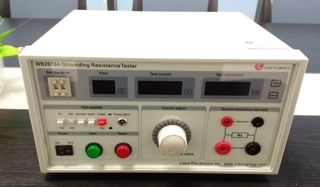
Figure 1
The main components are as follows:
| Number | Note |
| ① | Power Cord |
| ② | Test leads: one set of red leads and one set of black leads |
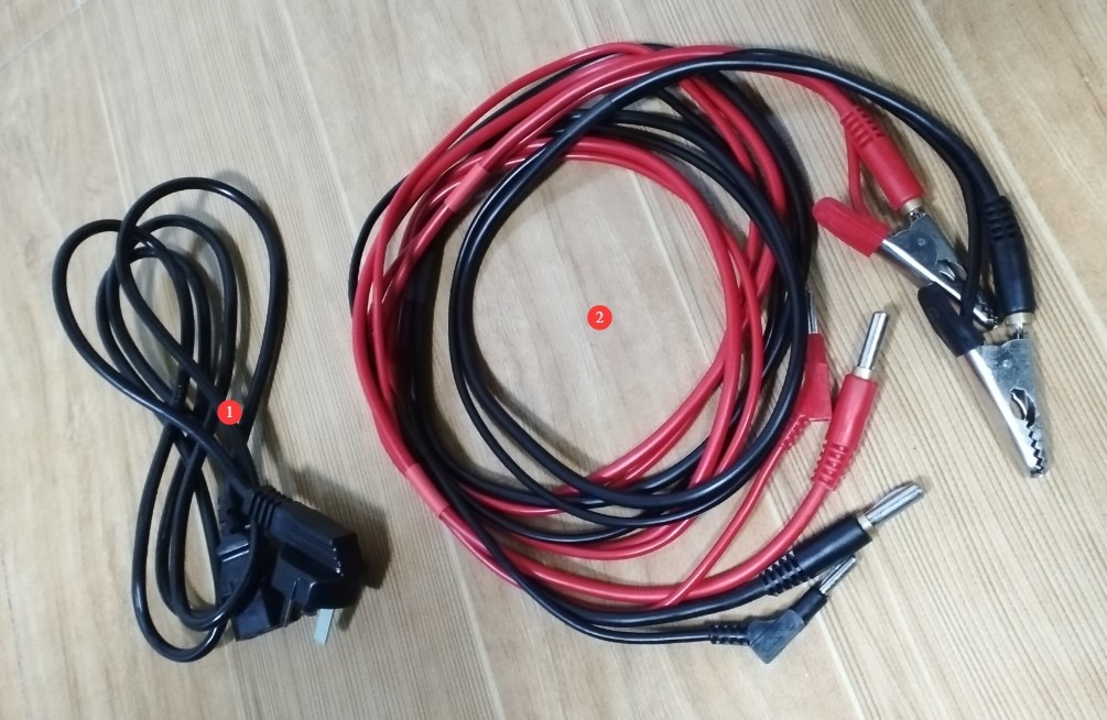
Figure 2
Download links for the digital user manual, software, warranty card, and other items have been sent via email. Please download them as soon as possible. If you missed the email, please feel free to contact us to receive the download links again.
2 Safety Precautions
2.1 Electrical Safety
2.1.1 Power Supply Requirements
Use a single-phase AC 220V ±10%, 50/60 Hz three-prong outlet; the ground prong must be connected to ground.
2.1.2 Grounding Requirements
The instrument ground wire is reliably connected to the protective ground wire, and the protective ground resistance is ≤4 Ω;
Do not manually short-circuit the output terminal to the AC power source to prevent the housing from becoming energized.
2.2 Environmental Safety
Test environment temperature: 0–40°C; relative humidity: ≤85% RH; no condensation;
Do not use in environments containing flammable or explosive substances, corrosive gases, or excessive dust;
Do not test the device in environments exposed to direct sunlight or near equipment that emits strong electromagnetic fields (such as large Voltage Transformers or arc welders) to avoid interference;
Place the equipment on a level, sturdy work surface, away from water sources and heat sources. Keep the main unit at least 10 cm away from the wall to facilitate heat dissipation.
2.3 Operational Safety
2.3.1 Wiring Safety
When connecting the dedicated test leads to the host port, the red wire must be connected to the red port and the black wire to the black port; reverse connections are strictly prohibited;
Connecting or disconnecting cables must be done while the equipment is powered off or reset; under no circumstances should test cables be plugged in or unplugged during testing;
The ground terminal of the test object must be clean and free of oxidation, and the test lead clamps must be securely fastened to the test object to prevent arcing caused by poor contact;
During testing, do not touch the metal connectors of the test leads, the DUT connection ports, or the DUT ground terminal with your hands.
2.3.2 Current Regulation Safety
When adjusting the loop current, turn the current adjustment knob slowly and closely monitor the value displayed in the current window. Never increase the current rapidly, as this may cause an overcurrent and damage the device under test;
The test current must not exceed the rated ground test current of the device under test; unless otherwise specified, the maximum current shall not exceed 25 A;
If an overcurrent alarm occurs during testing, immediately press the reset button and stop adjusting the current.
2.3.3 Equipment Testing Safety
Do not perform continuous testing at the maximum current of 25 A for extended periods. The duration of a single test should not exceed 99 seconds, and a 1-minute break is required after each continuous test to prevent the equipment from overheating.
2.4 Other
For matters not covered in this manual, please proceed with caution or contact us.
3. Equipment Overview and Wiring
| Number | Note |
| ① | Power Switch |
| ② | Test Duration Settings: Test duration can be set from 1 to 99 seconds; to be used in conjunction with a timer switch. |
| ③ | Test time display, in seconds. Note: Available only when the timer switch is enabled. |
| ④ | Current display window, showing the current in the test circuit, in amperes (A) |
| ⑤ | Resistance display window: Displays the ground resistance value of the test object in mΩ. The resistance value is displayed in real time during testing; when no test is in progress or the circuit is open, the display shows “1.” |
| ⑥ | Test Status Indicator: Test: Testing in progress; Alarm: Resistance exceeds threshold/overcurrent/open circuit + buzzer sounds |
| ⑦ | Test Voltage Selection Button: Pressed = 8V (AC), Released = 12V (AC) |
| ⑧ | Test resistance range selection button: when pressed, the range is 0–200 mΩ; when released, the range is 0–600 mΩ. |
| ⑨ | Timer switch: Press to enable the timer; release to disable it. |
| ⑩ | Alarm selection button: Press to enable the alarm; release to disable the alarm. |
| ⑪ | Preset/Test Switch: Press to enter preset mode; push up to enter test mode. |
| ⑫ | Resistance adjustment knob for setting the alarm resistance threshold; use in conjunction with the alarm selection button. |
| ⑬ | Current adjustment knob: Adjusts the current in the test circuit. During testing, turning the knob clockwise increases the current, and turning it counterclockwise decreases the current. |
| ⑭ | Connect the test object to the port and connect the four terminals correctly as shown in the diagram; do not connect them incorrectly. |
| ⑮ | Press the Start button to begin the test; the test light will turn on. |
| ⑯ | Reset button: cuts off the circuit current, stops the test, and clears the alarm |
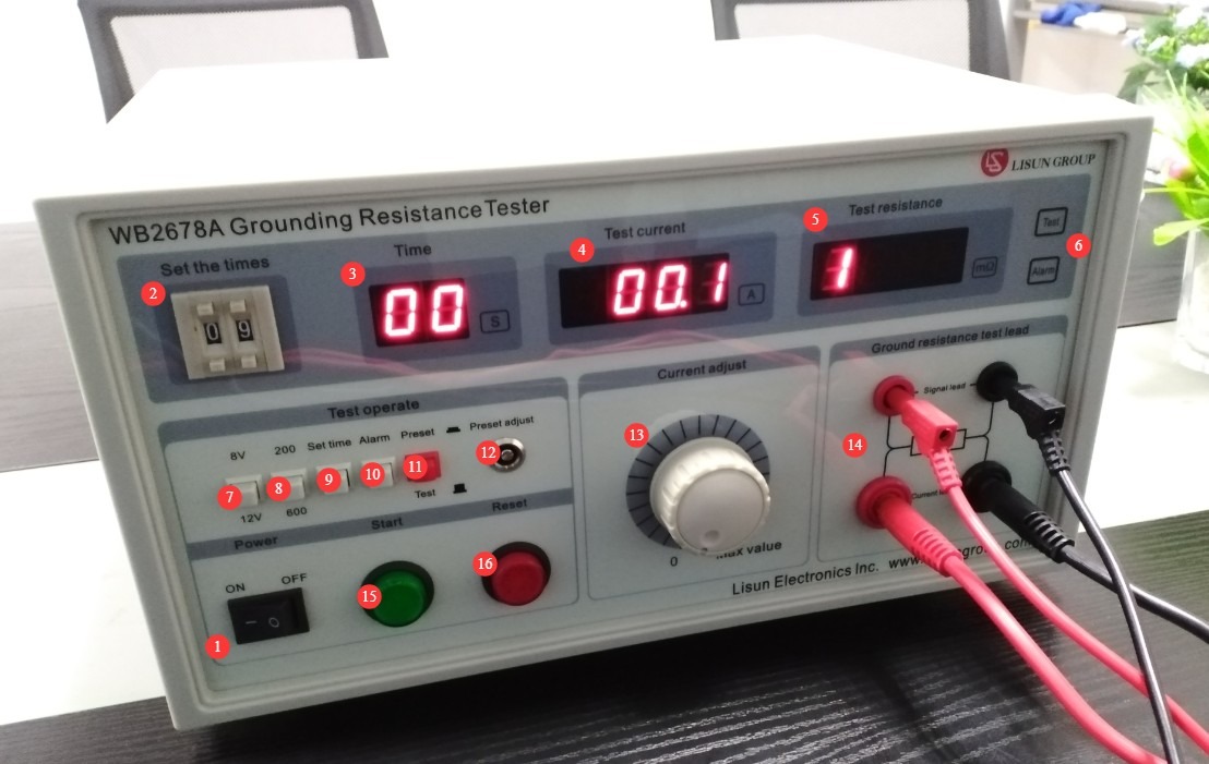
Figure 3
4. Preparations Before Testing
4.1 Test Parameter Presets
4.1.1 Selection of Output Test Voltage
Select 8 V (AC) first (by pressing the voltage selection button); at 8 V, the current adjustment resolution is higher, resulting in better measurement accuracy;
If the test current required by the test specimen cannot be adjusted at 8V, in the reset state, after the current has been adjusted back to zero, press the voltage selection button to switch to 12V (AC).
4.1.2 Selecting the Test Resistance Range
Select the range based on the ground resistance requirements of the test object: If the resistance to be measured is ≤200 mΩ, press the resistance range selection button to select the 0–200 mΩ range; if the resistance to be measured is >200 mΩ, press and release the resistance range selection button to select the 0–600 mΩ range;
Note: When selecting a measurement range, follow the principle of “better small than large”; a smaller range provides higher measurement accuracy.
4.1.3 Timer Parameter Settings
If you need to perform a timed test, press the timer switch and set the test duration to the desired length (1–99 seconds); the timer display window will show the set value;
If you do not need to run scheduled tests, toggle the timer switch to turn it off, and the test will switch to manual stop mode.
4.1.4 Alarm Parameter Presets
To enable the alarm function, press the alarm selection button; to disable it, release the button. Once the alarm function is enabled, clamp the red and black test leads together:
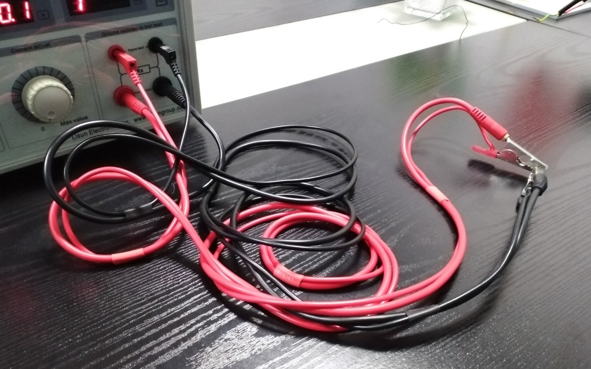
Figure 4
Set the Preset/Test switch to the Preset position, press the Start button, and slowly turn the current adjustment knob to the current required for the test (e.g., 10 A or 25 A);
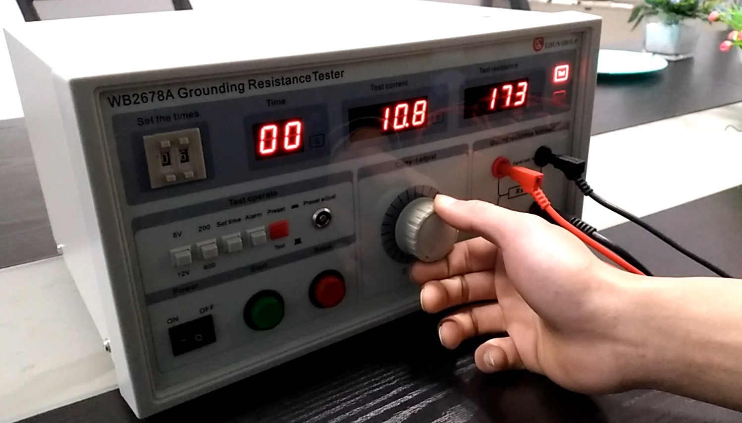
Figure 5
Turn the preset adjustment knob on the resistance alarm to set the value displayed in the resistance window to the ground resistance alarm threshold for the test object, thereby completing the preset.
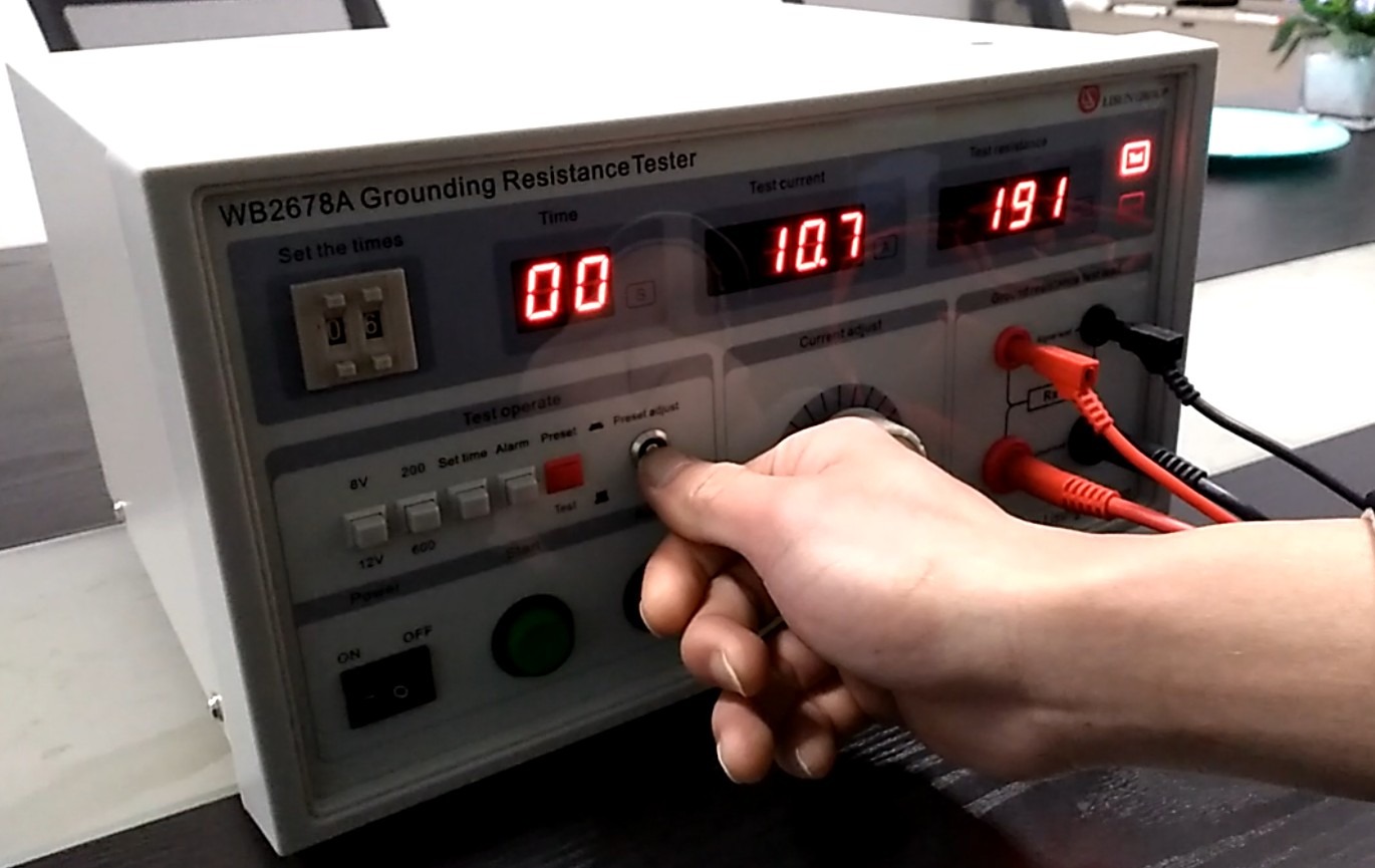
Figure 6
Then press the reset button to finish the preset and switch the preset/test selector to the test mode.
4.2 Preparation of the Test Specimen
4.2.1 Verification of the Test Object’s Condition
The test object’s casing must be clean and free of oil; place it in the center of the insulating mat, away from the metal work surface.
4.2.2 Connecting the Test Object
Clamp the red test lead’s alligator clip to the ground terminal of the device under test, and clamp the black test lead’s alligator clip to the test point on the device under test—a metal casing or conductive part;
There must be no gap between the chuck and the contact surface of the workpiece to ensure a reliable electrical connection. Do not clamp the workpiece by non-metallic parts or areas affected by oxidation or oil contamination;
After completing the wiring, check all connections again to ensure there are no loose connections or reversed polarity.
5. Test Procedure
5.1 Startup Test
After confirming that all parameter settings and wiring are complete, press the Start button; the test status indicator will light up, and the device will enter test mode.
5.2 Test Current Adjustment
Keep your eyes on the current display window and slowly turn the current adjustment knob clockwise to set the test circuit current to the value required for the device under test (between 3.5 A and 25 A);
If the current exceeds the target value during adjustment, slowly turn the knob counterclockwise; do not turn the knob rapidly;
Once the current has stabilized, observe the resistance display window; when the reading stabilizes, that value represents the ground resistance of the test object.
5.3 Test Data Recording
Timed Test: When the test countdown ends, the device automatically locks in the resistance value and records the current, resistance, and test duration at that moment;
Manual Test: Once the current and resistance values have stabilized, continue observing for 5 to 10 seconds and record the stable values;
If the alarm indicator lights up during the test, record the alarm type (overcurrent/resistance exceeds threshold/open circuit) and stop the test.
5.4 Post-Test Procedures
5.4.1 Standard Closing Procedures
After the test is complete, press the reset button first to cut off the current in the test circuit; the test status indicator will turn off;
Slowly turn the current adjustment knob counterclockwise to return the current to zero;
Disconnect the test lead connector from the test object, then disconnect the test lead connector from the main unit;
If you are finished testing, turn off the device’s power switch, unplug the power cord, and tidy up the test leads.
5.4.2 Emergency Stop Procedures
If any of the following abnormal conditions occur during testing, immediately press the reset button to stop the test immediately:
The value on the current display suddenly spiked, exceeding 25 A;
The test item emits smoke, makes unusual noises, or produces sparks;
The device is making unusual noises, emitting an unusual odor, or the screen is black;
The warning light stays on and cannot be turned off manually.
After an emergency stop, investigate the cause of the malfunction; do not conduct another test until the problem has been resolved.
5.5 Continuous Testing Procedure (Test Specimens Under Identical Conditions)
If you need to perform continuous testing on multiple test items of the same model and with the same test parameters, you can do so while the system is not in alarm mode. Follow these steps:
After the first test item has been tested, press the reset button to return the current to zero; there is no need to turn off the power or reset the parameters;
Remove the test lead clamp from the tested item and clamp it to the ground terminal or metal housing of the next item to be tested;
Press the start button, slowly adjust the current to the set value, and run the test;
Repeat the above steps to complete testing of all test items;
After testing no more than 10 test items consecutively, pause the test for 1 minute to allow the equipment to cool down.
6. Daily Maintenance and Care of Equipment
6.1 Routine Maintenance
Before turning on the equipment, check to ensure that the exterior is clean and free of damage, that the cables show no signs of aging or breaks, and that the connectors are secure. After testing is complete, disconnect the power and wipe down the equipment surface and the test area with a dry, antistatic cloth.
6.2 Long-Term Storage
When the device is not in use for an extended period, store it in a dry, well-ventilated area away from moisture and direct sunlight; disconnect all cables, store accessories separately, and cover the device with a dust-proof cloth; turn on the device and let it run for 30 minutes once a month to prevent the internal electronic components from deteriorating.
7. Troubleshooting and Resolving Common Problems
| Fault Symptoms | Possible Causes | Procedure |
| The device won’t turn on | Blown fuse | Check the fuse in the equipment’s input power supply port; if it is blown, replace it with a fuse of the same type. |
| Abnormal Test Current | The current adjustment is not complete, and there is an open circuit between the ground terminal of the device under test and the test point. | Before the official test, refer to Section 4.1.4 to preset the test voltage; during the official test, refer to Section 5.2 to fine-tune the test current; check whether the test points are conductive to ground or connected to the correct test points. |
| Poor repeatability of ground resistance measurements | The test lead connector is loose; the ground terminal of the test object has poor contact. | Re-clamp the test lead connector to ensure there is no play; clean the ground terminal of the test object to remove oxidation and oil residue. |
| During testing, the resistance display window shows 1. | There is an open circuit between the ground terminal of the device under test and the test point. | Check whether the test point is connected to ground, or whether it is connected to the correct test point. |
Appendix A: National Standards and Testing Requirements for Ground Resistance
This table summarizes the latest versions of national standards related to ground resistance for categories such as household appliances, medical equipment, lighting fixtures, and information technology equipment. It combines these standards with the technical specifications of the WB2678A Grounding Resistance Tester (8V/12V,3.5 A–25 A) to determine the appropriate test current and voltage. It specifies ground resistance limits, test durations, and special requirements, providing a basis for compliance when presetting equipment test parameters:
| Standard Number | Applicable Sample Types | Grounding Resistance Requirements | Test Duration | Recommended Test Current/Voltage (Compatible with WB2678A) | Other Testing Requirements |
| GB/T 4706.1-2024 | Household and Similar Electrical Appliances (refrigerators, washing machines, air conditioners, rice cookers, electric ovens, and other Class I appliances) | ≤0.1 Ω (excluding the resistance of the power cord) | ≥5 seconds | 1.5 times the appliance’s rated current / 25 A (whichever is greater), 8 V (AC) (preferred) | 1. Testing must cover all accessible metal parts, all of which must meet the resistance limits; 2. When grounding removable parts (such as refrigerator doors), the “connect first, then disconnect” principle must be followed; 3. The connection between the grounding terminal and the metal enclosure must be permanently reliable. |
| GB 9706.1-2020 | Medical electrical equipment (patient monitors, physical therapy devices, medical centrifuges, medical imaging equipment, and other Class I medical electrical equipment) | 1. Outlets with attached devices/permanently installed equipment: ≤100 mΩ; < BR>2. Equipment with non-removable or removable power cords: ≤200 mΩ | 5s/10s (depending on the device type) | 25 A / 1.5 times the equipment’s rated current (whichever is greater), 8 V (AC) (instrument-compatible; standard no-load voltage ≤ 6 V) | 1. If no original detachable flexible cable is available, use a 3-meter flexible cable with a standard cross-sectional area for testing; 2. For devices connected to patients, additional testing of ground continuity is required, and there must be no interruptions; 3. Perform the test three times in a row; no single measurement may exceed the threshold. |
| GB 7000.1-2024 | Lighting Fixtures (Fixed, Portable, and Recessed Class I Fixtures) | ≤0.5 Ω | ≥1 s | 10 A, 8 V (AC) | 1. The resistance between the grounding terminal and the luminaire’s metal housing is included in the test result; 2. The grounding resistance of the luminaire’s movable metal parts (such as the lamp arm) must be tested separately. |
| GB 4943.1-2022 | Information Technology Equipment (computers, printers, servers, routers, smart interactive terminals, and other Class I equipment) | ≤0.1 Ω | 120 seconds (continuous testing) | 25A (instrument-rated, standard includes 40A range), 8V (AC)/12V (AC) | 1. The test involves continuous monitoring of ground continuity throughout the entire process; power must not be interrupted during the test. 2. The test current should preferably be 1.5 times the equipment’s rated current, but must not exceed the instrument’s 25 A limit. 3. Live parts and ground terminals must both meet the insulation requirements. |
| GB/T 5226.1-2019 | Industrial Equipment (Machine Tools, Variable Frequency Drives, Industrial Motors, Electrical Equipment for Automated Production Lines) | ≥5 seconds | 25A, 12V (AC) | 1. Each test must be performed once with the equipment in both the cold and hot states, and the results must comply with the specified limits in both cases; 2. The grounding circuit must meet the requirement of a leakage current ≤ 0.75 mA; 3. The emergency stop device must be tested in conjunction with the grounding system, with a response time of ≤ 1 s. | |
| GB 50169-2024 | Electrical Facilities (low-voltage distribution equipment, Voltage Transformers, substation grounding grids, freestanding lightning rods) | 1. Working grounding of Voltage Transformers: ≤4Ω; < BR>2. Substation grounding grid: ≤0.5Ω; < BR>3. Lightning protection grounding for standalone lightning rods: ≤10Ω; < BR>4. Protective grounding for equipment in low-voltage TT systems: ≤4Ω | ≥10 seconds | 1. Before testing, the power facilities must be disconnected from the power grid, and power must be shut off throughout the entire process; 2. The substation grounding grid shall be measured using the “injection method,” and the average of three test results shall be taken; 3. In areas with high soil resistivity, resistance limits may be classified and handled in accordance with the specifications. | |
| JGJ/T 46-2024 | Temporary Electrical Equipment for Construction and Municipal Engineering (Tower Cranes, Construction Elevators, Temporary Distribution Boxes, Vibrators) | 1. Separate protective grounding: ≤4Ω; < br>2. Repeated grounding of the PE conductor: ≤10Ω; < br>3. Lightning protection grounding for tower cranes/scaffolding: ≤30Ω | ≥5 seconds | 20 A, 12 V (AC) | 1. At the construction site, perform one test at each of the three locations—the electrical distribution room, the intermediate distribution point, and the end point—and calculate the average value; 2. It is strictly prohibited to install switches or fuses on the PE conductor; verify that the PE conductor is not broken before testing; 3. Conduct a follow-up grounding resistance inspection at least once a month. |
| GB 3836.15-2024 | Electrical Equipment for Explosive Atmospheres (Explosion-Proof Distribution Panels for Gas Stations and Chemical Plants, Explosion-Proof Motors, and Dust-Proof Explosion-Proof Equipment) | 1. Equipment for Class IIIC conductive dust environments: ≤0.1 Ω; < br>2. Grounding for other explosion-proof environments: ≤4 Ω; < br>3. Anti-static grounding: ≤100 Ω | ≥10 seconds | 25A, 12V (AC) | 1. Testing is prohibited in explosive areas; operations must be conducted in a non-explosive environment; 2. Equipment designed for Class IIIC dust must be equipped with dual grounding/equipotential bonding and tested separately; 3. Grounding connectors must be compatible with copper-core conductors of ≥4 mm² and must make a secure connection without any looseness. |