
 English
 中文简体
中文简体 English
 Русский
 Español
 Português
 Türkçe
 العربية
 Deutsch
 Polski
 Italiano
 Français
 한국어
한국어 ไทย
ไทย Tiếng Việt
 日本語
日本語





























AC Withstand Voltage Tester
User's Manual
Applicable LISUN models: WB2673A、WB2673B、WB2673C
1. Unboxing and Basic Familiarization with the Equipment
1.1 Key Technical Specifications
| Model/Specifications | Test Voltage Range | Breakdown Current Range | Voltage Transformer Capacity | Test Duration | Accuracy |
| WB2673A | 0–5 kV (AC) | AC: 0–200 mA | 1 kVA | 1–99 seconds | ±5% |
| WB2673B | AC: 0–400 mA | 2 kVA | |||
| WB2673C | AC: 0–600 mA | 3 kVA |
1.2 Unboxing and Checking the Contents
1.2.1 Unpacking and Visual Inspection
When unpacking the device, handle it gently to avoid scratching the outer casing with sharp tools. After unpacking, first inspect the exterior of the device to ensure there is no visible deformation or dents, and that the buttons are not damaged or loose. If you notice any abnormalities with the device or its accessories, do not turn it on. Please contact us immediately.
1.2.2 Main Unit and Accessories
Host: 1 WB2673 host.
The main components are as follows:
| Number | Note |
| ① | Power Cord |
| ② | Test Power Cable |
| ③ | Grounding Clamp |
| ④ | High-voltage rod, including a high-voltage rod connection cable and a remote control cable; the handheld end of the high-voltage rod includes control buttons |
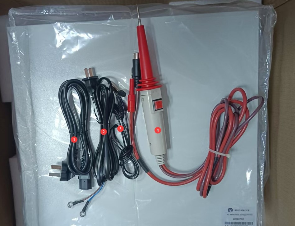
Figure 1
Download links for the electronic user manual, software, warranty card, and other materials have been sent via email. Please download them as soon as possible. If you missed the email, please feel free to contact us to request the download links again.
2 Safety Precautions
2.1 Electrical Safety
2.1.1 Power Supply Requirements
Use a single-phase AC 220V ±10%, 50/60 Hz three-prong outlet; the ground prong must be connected to ground.
2.1.2 Grounding Requirements
The instrument ground wire is reliably connected to the protective ground wire, and the protective ground resistance is ≤4Ω;
Do not short-circuit the output terminals to the AC power source to prevent the enclosure from becoming energized.
2.2 Environmental Safety
2.2.1 Temperature and Humidity Requirements
Avoid using the device in environments where humidity exceeds 70% (without condensation) or where the temperature is outside the range of 0–35°C. The optimal operating temperature is 25±2°C.
2.2.2 Environmental Contraindications
Environments with strong magnetic fields and strong electric fields;
Environments containing corrosive gases or liquids;
Areas with flammable and explosive dust or hazardous materials;
Environments with heavy dust, high temperatures and humidity, and direct sunlight.
2.3 Operational Safety
During testing, the housing of the test object is electrically charged; do not touch it with your bare hands under any circumstances;
The test object must be placed on a rubber insulating mat;
Operators must wear rubber insulated gloves;
Never short-circuit the high-voltage output terminal (high-voltage probe) directly to the ground terminal (ground clamp), as this may cause the internal Voltage Transformer to burn out;
Operators must have dry hands and must not wear any metal jewelry; eating or drinking is prohibited during testing to prevent accidents caused by electric shock;
Before replacing the test object, you must first stop the test and verify that the device’s output voltage is 0;
When multiple people are involved, clearly define roles and responsibilities, and confirm them with each other before starting the test to avoid errors.
2.4 Other
For matters not covered in this manual, please proceed with caution or contact us.
3. Equipment Overview
3.1 Introduction to the Equipment Front Panel
| Number | Note |
| ① | Power Switch |
| ② | High-voltage output connector, used to connect to the live parts of the device under test |
| ③ | Remote-controlled outlet; remote control wire connected to the high-voltage rod |
| ④ | Connect the grounding clamp; use the banana plug end to connect to the instrument, and the clamp end to connect to the device under test. |
| ⑤ | Test Time Settings: You can set the test duration from 1 to 99 seconds for use with a timer switch. |
| ⑥ | Test time display, in seconds. Note: Available only when the timer switch is enabled. |
| ⑦ | Leakage current display window: Displays the alarm threshold in standby mode and the real-time leakage current in test mode, in mA. |
| ⑧ | Output voltage display window, showing the current high-voltage output value in kV |
| ⑨ | Test Status Indicator: TE: Testing; NG: Leakage current exceeds threshold + buzzer sounds |
| ⑩ | Current adjustment knob: Sets the alarm current threshold; used in conjunction with the alarm selection button. |
| ⑪ | Preset/Test Switch: Press to enter preset mode; push up to enter test mode. |
| ⑫ | Timer switch: Press to enable the timer; release to disable it. |
| ⑬ | Residual Current Range Selection Button; the ranges are interlocked, so only one range can be selected at a time. |
| ⑭ | Output voltage adjustment knob: Turn clockwise to increase the output voltage; turn counterclockwise to decrease it. |
| ⑮ | Press the Start button to begin the test; the test light will turn on. |
| ⑯ | Reset button: cuts off the output voltage, stops the test, and clears the alarm |
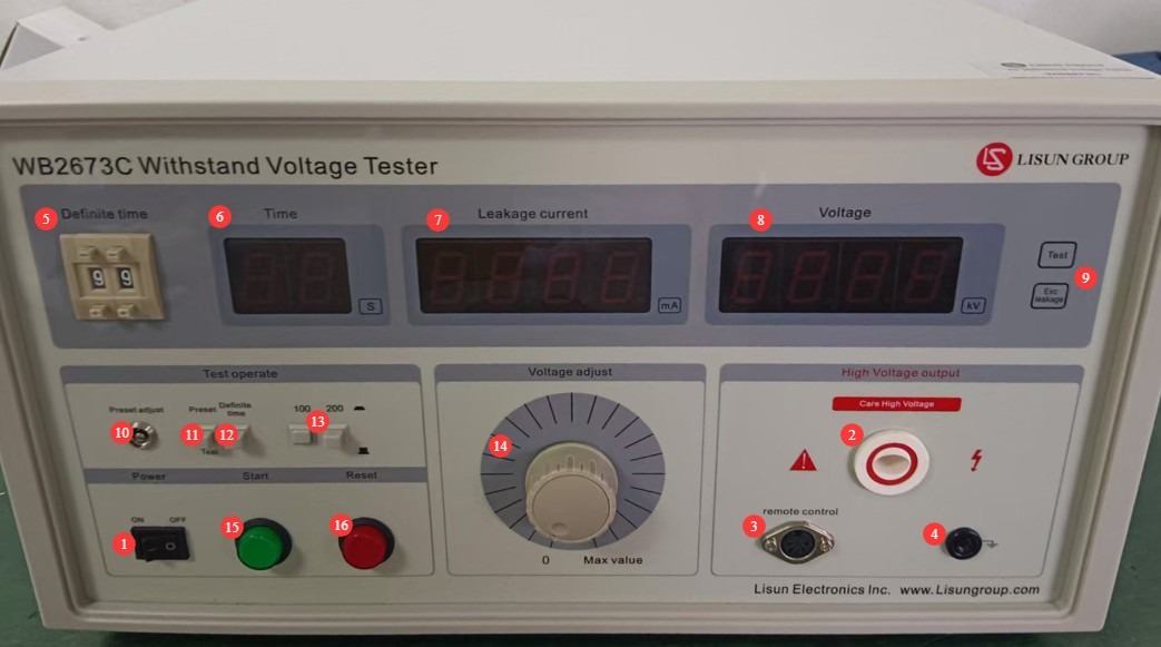
Figure 2
Note: Once the remote control cable is connected, the power and reset buttons on the device’s front panel will not function.
3.1 Introduction to the Equipment Back Panel
| Number | Note |
| ① | Power cord receptacle, with built-in fuse |
| ② | To connect the test power supply terminals, use the test power supply connection cable to connect to a 220 V AC ±10%, 50/60 Hz power source. |
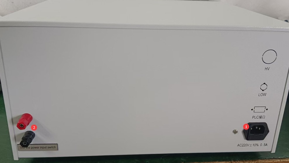
Figure 3
4. Preparations Before Testing
4.1 Powering On the Equipment
Plug the power cord into a standard three-prong outlet, press the power switch, and the instrument’s display will light up. The TE and NG indicator lights will be off, and the leakage current and voltage displays will show 0. If there are no abnormal audible or visual alarms, this indicates that the device’s power-on self-test was successful.
4.2 Preparation of the Test Specimen
The test object’s casing must be clean and free of oil; place it in the center of the insulating mat, away from the metal work surface.
5. Test Procedure
5.1 Test Parameter Presets
All parameter presets must be completed by following the steps below, with the high-voltage rod, remote control cable, and grounding clamps removed.
5.1.1 Selection of Leakage Current Range
Select the appropriate leakage current range button based on the standard requirements for the test item.
5.1.2 Setting the Leakage Current Alarm Threshold
Switch the Preset/Test button to the preset state.
Slowly turn the current adjustment knob while observing the leakage current display window, and adjust the value to the alarm threshold specified in the test item’s standards.
Once the settings have been configured, switch the Preset/Test button to the Test mode; the leakage current display will return to 0, and the alarm value will be automatically saved.
5.1.3 Setting the Test Duration
Select either manual mode or timer mode according to the test standard requirements:
Manual Mode: Flip the timer switch to the “On” position; there is no need to set a time—the operator manually controls the test duration.
Timer Mode: Press the timer switch to set the test duration to the required length (1–99 seconds); the time will be displayed as a countdown.
5.1.4 Output Voltage Setting
Press the Start button and observe the value displayed in the output voltage display window. You can adjust it to the standard required value by turning the output voltage adjustment knob. Once adjusted, press the Reset button.
Note: For tests with specified voltage rise rates, do not preset the voltage; simply turn the knob to 0. Once the test has officially begun, slowly turn the knob to adjust the output voltage to the test voltage at the rate specified in the standard.
5.2 Equipment Wiring
| Instructions | Note |
| ① | Insert the banana plug end of the grounding clamp into the instrument’s connector, and verify that the ground terminal or metal casing of the device under test is securely connected to the clamp’s grounding terminal. |
| ② | Plug the remote control cable for the remote-controlled high-voltage rod securely into the remote control socket on the main unit. |
| ③ | Securely connect the high-voltage probe cable to the AC high-voltage output port on the main unit, and keep the high-voltage probe’s output end away from the test object for the time being. |
5.3 Withstand Voltage Test
5.3.1 Startup Test
Place the output end of the high-voltage probe in close contact with the live parts of the test object (such as the power cord input or the winding leads). Then press the output control button on the high-voltage probe to begin the test.
5.3.2 End of Testing
In timer mode, when the countdown ends, the high voltage is automatically disconnected and the test stops; in manual mode, the test stops when you release the high-voltage probe control button.
If any of the following abnormalities occur during testing, the test must be stopped immediately: smoke, unusual noises, or sparks from the test item; unusual noises, strange odors, or a black screen on the display. After an emergency stop, investigate the cause of the abnormality; do not resume testing until the problem has been resolved.
5.4 Evaluation of Test Results
The test results are evaluated primarily based on whether breakdown has occurred and whether the leakage current exceeds the threshold.
5.4.1 Acceptance Criteria
Throughout the entire test, the voltage remained stable at the standard requirement value, and the real-time leakage current remained below the set alarm threshold at all times; the “NG” indicator light and buzzer alarm were not triggered.
5.4.2 Criteria for Determining Nonconformity
During testing, if the leakage current exceeds the alarm threshold, the “NG” light turns on and the buzzer sounds.
The test specimen exhibits obvious signs of breakdown, flashover, smoke, etc.
6. Daily Maintenance and Care of Equipment
6.1 Routine Maintenance
Before turning on the equipment, check to ensure that the exterior is clean and undamaged, that the cables show no signs of aging or breakage, and that the connectors are secure; Check the grounding clamps for oxidation or burn marks; if present, wipe them with a specialized contact cleaner, and contact us to replace parts if necessary; after testing is complete, disconnect the power and wipe down the equipment surface and the test area with a dry, antistatic cloth.
6.2 Long-Term Storage
When the device is not in use for an extended period, store it in a dry, well-ventilated environment, away from moisture and direct sunlight; disconnect all cables, store accessories separately, and cover the device with a dust-proof cloth; turn the device on for 30 minutes once a month to prevent the internal electronic components from deteriorating.
7. Troubleshooting and Resolving Common Problems
| Fault Symptoms | Possible Causes | Procedure |
| The device won’t turn on | The power cord isn’t plugged in securely; the fuse has blown. | Check the power cord connections; check the fuse in the device’s power input port; if it is blown, replace it with a fuse of the same type. |
| After startup, the display flickers and the keys do not respond. | Unstable power supply voltage | Use a multimeter to measure the supply voltage and verify that it is within the range of AC 220 V ±10%. If the voltage is unstable, install a voltage regulator. |
| Unjustified alarms during testing | Incorrect selection of the leakage current range; incorrect setting of the alarm current threshold | Please select the correct leakage current range first, then adjust the alarm current threshold. |
Appendix A: Summary Table of AC Withstand Voltage Test Requirements in Relevant Standards
| Standard Number | Types of Electronic Products Covered | Dielectric Withstanding Voltage Test Requirements | Breakdown Current / Leakage Current Limits | Test Duration | Other Testing Requirements |
| GB/T 24344-2009/IEC 60204-1:2021 | Electrical and electronic equipment and systems for industrial machinery; electrical systems for machinery with a rated voltage of ≤1000 V AC or 1500 V DC | 1. Basic insulation: 2 × rated voltage + 1000 V, with a minimum of 1500 V AC; 2. Rated voltage ≤ 60 V: 500 V AC; 3. 60 V < rated voltage ≤ 300 V: 1000 V AC; 4. 300 V < rated voltage ≤ 690 V: 1500 V AC; 5. Frequency: AC voltage between 45 Hz and 65 Hz, with a waveform approximating a sine wave, and a peak-to-root-mean-square (RMS) ratio within √2 ± 0.07 | The test is considered successful if there are no breakdowns or flashovers; leakage current serves as a supplementary evaluation criterion, and there is no specific fixed limit. | 1. Standard test: 1 minute; 2. Rapid test: at least 1 second (as specified in IEC 60204-1:2021) | 1. The test voltage should start at 0 and be increased uniformly to the specified value; avoid sudden voltage increases; 2. After the test, slowly reduce the voltage to zero; 3. Applicable to dielectric strength tests for industrial machinery and electrical equipment, covering protection against electric shock, equipment protection, and more. |
| GB 4706.1-2024/IEC 60335-1:2023 | Household and similar electrical appliances with a rated voltage not exceeding 250 V for single-phase appliances and 480 V for other appliances, including refrigerators, air conditioners, electric irons, blenders, and other types of home appliances | 1. Basic insulation: 1000 V + 2× rated voltage, minimum 1500 V AC; 2. Reinforced insulation: 2000 V + 4× rated voltage, minimum 3000 V AC;3. Class 0 and Class I appliances: 1250 V AC; 4. Class II appliances: 1750 V AC; 5. Frequency: 50 Hz/60 Hz power-frequency sine wave | 1. The test is considered satisfactory if no breakdown, arcing, or flashover occurs during the test; 2. The high-voltage power supply must be capable of supplying the specified short-circuit current when a short circuit occurs at the output;3. Leakage current limits: 0.25 mA for Class II equipment; 0.5 mA for Class 0, Class I, and Class III equipment | 1. Routine testing: 1 minute; 2. In special cases, follow the specific provisions of the standard. | 1. The test shall be conducted at room temperature; for Class 0 and Class I appliances, a moisture treatment must be performed prior to the test; 2. For Class II designs that feature both reinforced insulation and double insulation, care must be taken to ensure that the voltage applied to the reinforced insulation does not cause excessive stress on the basic insulation or supplementary insulation;3. When testing the insulating covering, sandbags may be used to apply a pressure of approximately 10 kPa. |
| GB 19212.1-2021/IEC 61558-1:2022 | Voltage Transformers, reactors, power supply units, and their combined products, including Isolation Transformers, safety isolation transformers, autotransformers, and variable transformers; switching power supplies, inductive ballasts, chargers, etc., with a rated voltage not exceeding 1000 V AC or 1500 V DC. National Standard Information Public Service Platform | 1. Between windings and between windings and the housing: 2500 V to 4000 V AC (determined based on the insulation class and rated voltage);2. Basic insulation: 1000 V + 2× rated voltage; 3. Reinforced insulation: 2000 V + 4× rated voltage; 4. Frequency: 50 Hz/60 Hz power-frequency voltage | The test is considered satisfactory if no breakdown or arcing occurs; the leakage current must comply with the product-specific safety requirements. | 1 minute (60 seconds) | 1. The test voltage shall be gradually increased to the specified value within 5 seconds; 2. Applies to general safety requirements for Voltage Transformers, reactors, power supply units, and combinations thereof; 3. Emphasizes the ability to maintain protection against electric shock, overheating, and mechanical injury even under single-fault conditions |