
 English
 中文简体
中文简体 English
 Русский
 Español
 Português
 Türkçe
 العربية
 Deutsch
 Polski
 Italiano
 Français
 한국어
한국어 ไทย
ไทย Tiếng Việt
 日本語
日本語





























Thermally Protected Ballast Heating Test Chamber
User's Manual
Applicable LISUN models: TPB-UL935
1. Overview
The TPB-UL935 is a test chamber equipped with a thermal protection ballast that simulates high-temperature natural environments, specifically designed for testing the temperature resistance of electronic and electrical components. It complies with Appendix D of the GB19510.1-2009/IEC61347-1:2012 standard and UL935.
2. Important Notes
This product must be reliably grounded and kept away from sources of electromagnetic interference (never use the neutral wire or center conductor as a ground wire).
Before use, please verify that the supply voltage matches the product specifications.
The product should be plugged into a dedicated outlet, and you should ensure that the plug and outlet are properly grounded.
Do not unplug or plug in the power cord while the product is running without first turning off the power switch.
Do not arbitrarily extend or shorten the product’s power cord.
Do not attempt to repair the product on your own; repairs authorized by our company must be performed by qualified professionals.
! Warning (May result in property damage or personal injury)
You must thoroughly read and understand this product’s instruction manual before operating it.
When unplugging the power cord, never pull directly on the cord.
Unplug this product from the power source if any of the following conditions apply:
When replacing electrical components;
When a product malfunctions and needs to be inspected and repaired;
When the product is not in use for an extended period of time;
When moving products;
! Caution (This may affect the product’s service life and cause it to malfunction.)
When handling the product, take care to avoid damaging fragile components, such as the gauges on the panel.
When moving products with a cooling function, the angle of inclination must not exceed 45°. After placing the product in its designated location, allow it to stand undisturbed for (1–2) days before turning it on to ensure the cooling system operates normally and to extend its service life.
The product should be placed on a hard, stable, level surface to ensure it remains level.
Leave some space around the product. (See Section IV: Detailed Instructions for Use.)
The product must be used under specific conditions. (See Section IV for detailed instructions on use.)
Never pull the product door upward (to open) or downward (to close) with force, as this may cause the door to detach, resulting in product damage or injury.
When the product is not in use for an extended period, it should undergo periodic moisture removal treatment to prevent damage to the relevant components.
The thermal protection-type ballast heating chamber is a testing device that simulates high-temperature environments found in nature, specifically designed for temperature adaptation testing of electronic and electrical components.
3. Technical Specifications
3.1 Model and Specifications:
Model (): RZL-JT
Chamber dimensions (): 610 × 610 × 610 mm
Temperature range (): RT+10°C to +200°C
Total Power: 1.2 kW
Power Supply Voltage: AC 220 V, 50 Hz
3.2 Structure and Materials:
Inner Chamber Material: High-Grade Stainless Steel Sheet
Outer Case Material: Powder-coated steel plate
Insulation Material: Ultra-fine glass wool insulation
Heaters: Specialized flat-bar heaters (heating surface area: 300 mm × 40 mm), 300 watts per set, four sets total, connected in parallel to the power supply.
3.3 Temperature Controller:
Temperature Controller Specifications: Accuracy: 0.1°C
Resolution: 0.1°C
Temperature-sensing element (): Thermocouple test sensor
Control Method, ): Thermal Equilibrium Temperature Control
4. Instructions for Use
4.1 Equipment Installation Requirements:
D
4.2 Note: Using this equipment at temperatures outside the range of +5 to -35°C may shorten the service life of its components or cause malfunctions. The Company does not provide warranty coverage for such malfunctions.
Figure 1
Distance between the instrument and surrounding objects: front > 600 mm, rear > 300 mm
Left/Right > 300 mm, Up > 300 mm
4.3 Once the equipment has been installed in its designated location, follow these steps:
After the equipment is placed on the floor, if the surface is uneven, it should be leveled with shims.
Plug the device’s three-prong plug into a power outlet and set the power switch on the right side of the panel to the “On” position. At this point, a digital display will appear on the control panel, indicating that the device has entered operating mode;
Set the desired control parameters by configuring the temperature controller. A schematic diagram of the control panel is shown below:
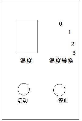
4.4 Controller Instructions:
After turning on the power switch, if the instrument temperature needs to be reset, press the “SET” button once to enter the temperature setting screen. Use the “<” digit shift key and the “∨” and “∧” keys to set the desired temperature according to test requirements, then press the “SET” key twice to confirm. Once set, press the Start button to activate the instrument’s heating elements; press the Stop button to turn off the heating.
The four-phase switches in the control panel correspond to the three heaters in the instrument’s working area, allowing the operator to turn them on or off as needed.(To switch modes, rotate the switch clockwise. Position 0 is neutral and performs no action; positions 1, 2, and 3 correspond to the temperature controls for the front left, front right, and rear right sections of the chamber, respectively.)
Function button: Stop heating
4.5 Maintenance Instructions:
To ensure the instrument’s service life, please follow the operating instructions and instrument manual when using it.
Avoid placing the instrument in locations subject to strong vibrations or strong magnetic fields, outdoors, or in areas with poor ventilation and exposure to direct sunlight.
If the device will not be used for an extended period, be sure to disconnect it from the power source and store it with both the interior and exterior surfaces clean.
Packing List
| 1. Host | 1 unit |
| 2. Power Cord | 1 piece |
| 3. Sample Holder | 1 |
| 4. User Manual | 1 piece |
| 5. Product Certificate of Conformity | 1 serving |
| 6. Product Warranty Card | 1 serving |