
 English
 中文简体
中文简体 English
 Русский
 Español
 Português
 Türkçe
 العربية
 Deutsch
 Polski
 Italiano
 Français
 한국어
한국어 ไทย
ไทย Tiếng Việt
 日本語
日本語





























Surge Generator
User's Manual
Applicable LISUN models: SG61000-5C、SG61000-5HC
1. Unboxing and Basic Familiarization with the Equipment
1.1 Key Technical Specifications
| LISUN Model | SG61000-5C |
| Turn-On Voltage Waveform | 10/700 μs ± 20% |
| Short-Circuit Current Waveform | 5/320 μs ± 20% |
| Output Impedance | 15 Ω and 40 Ω |
| Output Voltage Range | 0–6 kV ±5% |
| Output Current Range | 0–150 A ±5% |
| Number of surges | 1–9999 times |
| Polarity | Positive Terminal, Negative Terminal, and Fully Automatic |
| Phase Shift | Asynchronous, Synchronous: 0°–360° or specified angle testing |
| Special Features | Brand-new free upgrade: Includes a built-in voltage and current attenuator probe and an electronic oscilloscope, allowing you to view output waveforms directly on the touchscreen! |
| Operating Instructions | LCD touchscreen input, built-in Android operating system |
| Dimensions (W x D x H) | 44 × 45 × 155 cm |
| Gross Weight | About 130 kg |
| Coupling Decoupling Network (Built-in CDN) | 4-Line Symmetric CDN |
| Coupling Decoupling Network for Communication Lines (Optional External CDN) | Options are available based on the type of test object, data transmission rate, and surge output waveform. For details, see the Shanghai LISUN CDN61000-5C. |
1.2 Unboxing and Checking the Accessories
1.2.1 Unpacking and Visual Inspection
When unpacking the device, handle it gently to avoid scratching the exterior casing with sharp tools. After unpacking, first inspect the exterior of the device to ensure there is no visible deformation or dents, and that the buttons are not damaged or loose.
If you notice any damage or deformation to the equipment or accessories, do not turn on the power. Please contact us immediately.
1.2.2 Main Unit and Accessories
Main Unit: 1 Surge Generator.
Standard Accessories: ① Ground wire, used to connect to the PGND protective ground terminal; ② Coaxial cable, used to connect to an external oscilloscope for monitoring surge waveforms; ③ Spare connection cable; ④ Discharge tube, used to check for surge output in the event of a device malfunction; ⑤ Power cord.
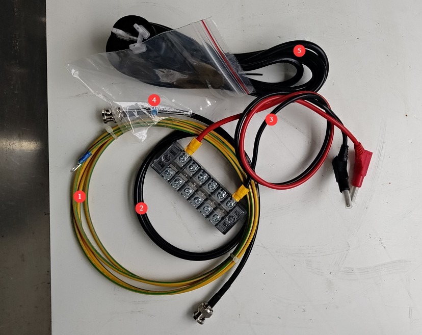
Figure 1
Note: The SG61000-5C is designed for surge testing of network and signal lines, so connection cable ③ is generally not needed; please store it properly for future use.
The download links for the digital user manual, warranty card, and other documents have been sent to you via email. Please download them as soon as possible. If you missed the email, please feel free to contact us to request the download links again.
1.3 Description of Equipment Structure
1.3.1 Front of the Device
① High-voltage indicator light; ② You only need to connect the wires here if you have an external CDN to connect; otherwise, no changes are necessary (keep the U-shaped plug inserted as shown in the figure); ③ Built-in CDN surge output, used to connect RS232/485, Ethernet cables, etc., as well as the EUT(Equipment Under Test); ④ Touchscreen; ⑤ Use a coaxial cable to connect an oscilloscope to view the surge output waveform; ⑥ USB port—use a USB mouse to control the touchscreen or connect a USB flash drive to upgrade the software; ⑦ Power switch.
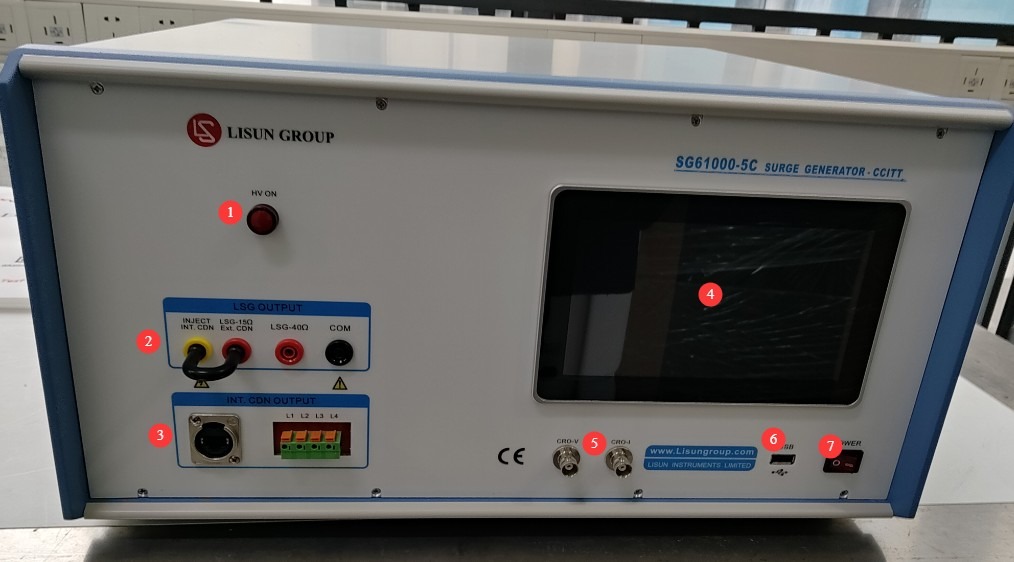
Figure 2
1.3.2 Back of the Device
① Power cord jack; ② Connections for the remote control and external CDN—these must be purchased separately; if you do not have them, do not connect them; ③ PGND protective ground terminal—please ensure the device is properly grounded;④ Safety connection—simply ensure the U-shaped plug remains inserted, as shown in the figure; ⑤ AE (Assistant Equipment) port—used to connect RS-232/485 cables, Ethernet cables, and auxiliary equipment (such as computers and EUT software).
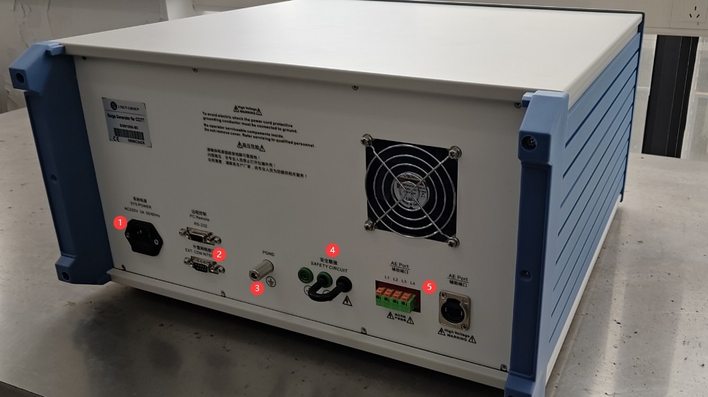
Figure 3
2. Safety Precautions
2.1 Placement Guidelines
Place it on a stable work surface; avoid tilting or inverting it, and keep it away from sources of vibration;
Isolation Transformer: Keep it at least 0.5 meters away from the main unit to avoid electromagnetic coupling interference;
The premises must be free of strong electromagnetic interference, corrosive gases, and flammable or explosive materials, and must be well-ventilated;
The equipment must be placed at least 1000 mm away from walls and surrounding structures (such as other test equipment and shelves) to facilitate maintenance; at least 2000 mm of space must be left in front of the equipment to ensure smooth operation and keep the surrounding area free of obstructions.
2.2 High-Voltage Safety Standards
2.2.1 Security Check
Verify that the equipment’s power supply voltage matches the mains voltage (AC 220 V ±10%, 50/60 Hz), and ensure that the power supply is properly grounded and that the grounding wire is free of damage or looseness;
Grounding Requirements: The host unit’s protective grounding terminal (PGND) must be connected to ground, with a grounding resistance of ≤4 Ω, to ensure safe discharge of high voltage;
Confirm ambient temperature: 15°C to 35°C, relative humidity: 10% to 75% (no condensation), atmospheric pressure: 86 kPa to 106 kPa;
Operators must have dry hands and must not wear any metal jewelry.
2.2.2 Safety Requirements for Operational Procedures
The equipment generates high voltages (up to 6 kV) and high-current surges during operation. Do not touch the pulse output connector, the EUT terminals, or the CDN port under any circumstances.
Before switching connections or replacing the EUT, you must first ensure that the high-voltage output is turned off (the HV indicator light is off) and wait at least 5 minutes to ensure that the internal high-voltage capacitors are completely discharged.
Do not eat or drink during the test to prevent accidents caused by electric shock.
When multiple people are involved, clearly define roles and responsibilities, and confirm them with each other before starting the test to avoid errors.
Do not disassemble the equipment or work with the casing open without authorization. The equipment contains high voltage, and repairs by non-professionals may result in electric shock or damage to the equipment.
2.3 Emergency Response Measures
In the event of an electric shock: Immediately shut off the main power supply to the equipment, move the operator to a safe area, administer first aid if necessary, and contact medical personnel.
Equipment Malfunction (Smoke, Unusual Noises, Strange Odors): Immediately shut down the equipment, disconnect the power supply, and disconnect all wiring. Do not turn the equipment back on. Contact the manufacturer for repairs.
Abnormal surge output: Pause the test, contact the manufacturer for troubleshooting, and do not touch the test port directly with your hands.
2.4 Other
For matters not covered in this manual, please proceed with caution or contact us.
3. Surge Test Procedure
3.1 Hardware Wiring Sequence
Refer to Section 1.3 and connect the wires in the following order:
Computers, software, or other AE auxiliary equipment > Communication cable > SG61000-5C rear AE port > SG61000-5C front CDN output port > Communication cable > EUT (Equipment Under Test).
3.2 Confirmation of Test Parameters
3.2.1 Selection of Test Level
Based on the EUT installation environment and product standards, select the corresponding test level (the priority levels are listed in the table below); lower levels must meet compatibility requirements:
| Test Level | Breakdown Test Voltage (±10%) | Applicable Scenarios |
| Level 1 | 0.5 kV | A well-maintained indoor environment |
| Level 2 | 1.0 kV | Typical Indoor Environment |
| Level 3 | 2.0 kV | Outdoor or semi-outdoor environments |
| Level 4 | 4.0 kV | Harsh outdoor environments |
| X-Class | Specific Voltage | Special scenarios specified in product standards |
3.3 Equipment Warm-up and Self-Test
Turn on the power switch on the front panel of the host; the device enters standby mode, the power indicator light turns on, and the cooling fan starts up.
Wait 5 minutes for the device to warm up, and check that the touchscreen is displaying properly and that no error messages appear.
3.4 Introduction to the Touchscreen Program
Program Startup Screen: ① Settings screen for the built-in digital oscilloscope; ② Important usage notes (this feature is not yet fully developed; do not perform any operations here at this time); ③ System information screen; ④ Chinese/English language switch; ⑤ Surge test screen.
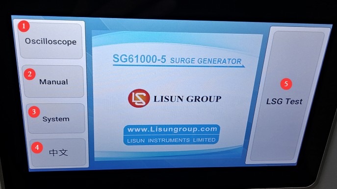
Figure 4
3.4.1 Oscilloscope Function Settings Interface
Just check all the boxes, and the current surge waveform will be displayed automatically after each surge test.
3.4.2 Surge Test Interface
① Surge voltage and polarity settings; ② Surge interval settings; ③ Number of surges; ④ Click to start or stop the surge test.
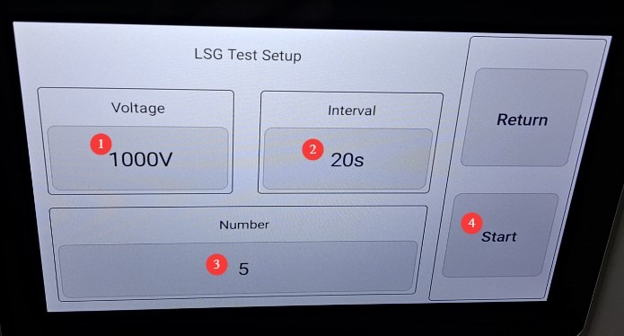
Figure 5
Note: To automatically display the current surge waveform on the screen, set the surge interval to at least 10 seconds; otherwise, the program will not have enough time to display the surge waveform.
3.5 Click “Start Test”
Once you have completed the above wiring and settings, click “Start” to begin the surge test.
3.6 Determining Whether the EUT Has Passed the Test
| Level | Evaluation Criteria | Passed or Failed | Typical Symptoms |
| Grade A (Criterion A) | Performance is completely normal within the specified limits, with no abnormalities whatsoever. | Usually deemed to have passed | No downtime, resets, display glitches, or data loss; key parameters are within acceptable limits. |
| Grade B (Criterion B) | Temporary loss or reduction in function or performance, but recovery occurs automatically once the disturbance ceases, without requiring operator intervention | Must be arranged in advance; generally acceptable | Automatic recovery after a brief communication interruption; returns to normal after screen flickering; returns to normal after a brief deviation from parameters |
| Class C (Criterion C) | Temporary loss or reduction in function or performance that requires manual intervention to restore (e.g., restart, reset) | Must be arranged in advance; acceptable in certain situations | If the equipment freezes, it must be manually restarted; if a program crashes, it must be reloaded; if parameters are out of range, they must be adjusted manually. |
| Grade D (Criterion D) | Irreversible loss of functionality or reduced performance due to hardware/software damage or data loss | Determined to be a failure | Components burned out, circuit boards damaged, stored data permanently lost, core functions irrecoverable |
4. Post-Test Procedures
4.1 Test Completion
If the EUT is visibly damaged during the test, immediately tap “Stop Test” on the touchscreen.
If no abnormalities occur during the test, wait for the surge test to complete automatically.
Wait 5 minutes to ensure that the high-voltage capacitors inside the main unit have completely discharged before replacing the EUT for testing, or turn off the power to the main unit and the Isolation Transformer.
4.2 Post-Test Organization and Cleanup
Verify whether the EUT has passed the test (no performance degradation, no damage).
Clean the test area and wipe it down with a dry cloth. Do not use alcohol or corrosive cleaning agents.
Surge testing is a destructive test; it does not automatically generate a test report, but the device automatically saves the test data. You can go to “System Information,” click “Test Log,” and export the corresponding test data to a USB flash drive via the USB port. The exported file is in TXT text format.
Figure 23
4.3 Equipment Storage
4.3.1 Short-Term Storage Requirements
If the equipment is used on a daily basis, no further action is required after cleaning is completed following each test.
4.3.2 Long-Term Storage Requirements
If the device will not be used for an extended period (more than one month), please disconnect all cables and cover the device with a dust cover to prevent dust buildup.
The device should be powered on once a month for just half an hour to prevent the aging of electrical components (such as capacitors and contactors).
5. Use a discharge tube to verify the surge output
A discharge tube can be used to easily verify whether a device produces surge output.
There is no need to connect the AE equipment or the EUT. ① Connect the L1, L2, L3, and L4 output ports of the CDN surge generator together to one end of the discharge tube. ② Connect the COM port to the other end of the discharge tube.
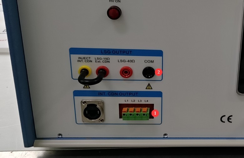
Figure 6
Set the voltage to 4 kV and begin the surge test. The discharge tube will flash the moment the surge is output; please dim the lights in the room to facilitate observation. See the figure below:
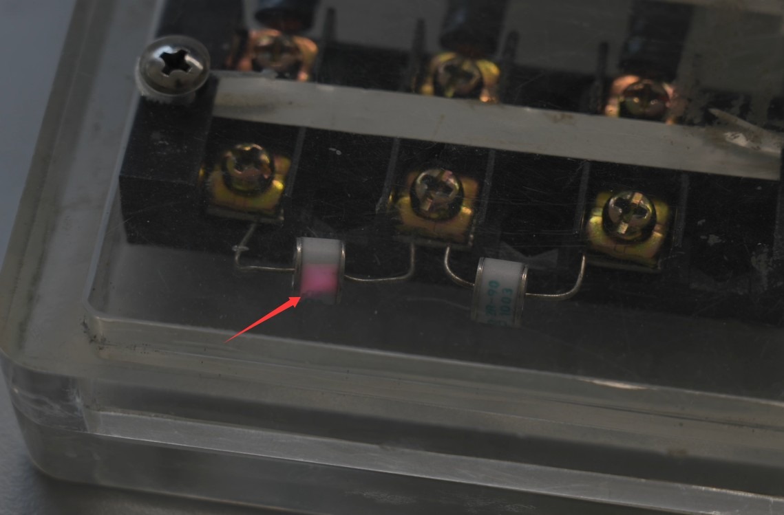
Figure 7
This confirms that the device is indeed experiencing an output surge. If the discharge tube does not flash, please contact customer service.
6. Troubleshooting and Resolving Common Problems
6.1 The device won’t turn on
Symptom: After turning on the power switch, the device does not respond (the indicator light does not come on, and the fan does not spin).
Possible causes: ① The power cord is not properly connected or is damaged; ② Abnormal supply voltage; ③ A blown fuse; ④ A blown varistor (MOV).
Troubleshooting: Ensure the power cord is intact and securely connected. Power supply issues—such as unstable voltage, excessively high voltage, or harmonic interference—can cause the fuse or varistor to burn out. We recommend using a voltage-stabilized, pure sine wave AC power supply to power the device. Replace the fuse or varistor with one of the same type.
The following image shows the fuse locations:
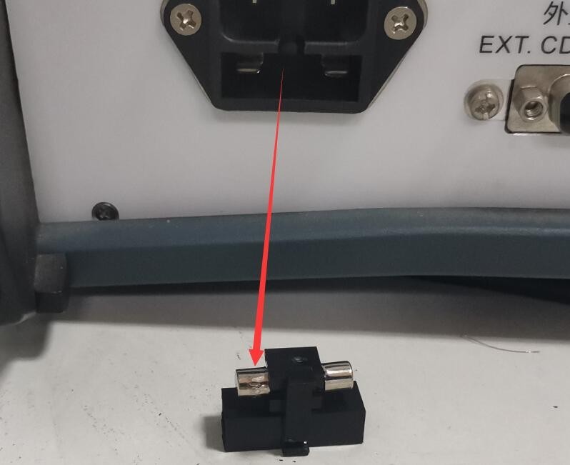
Figure 8
The following figure shows the location of the varistor (MOV) inside the filtered power supply:
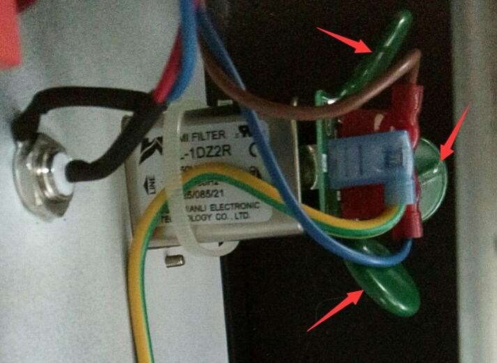
Figure 9
6.2 Automatic Device Restart
Symptom: The device automatically restarts when a surge occurs.
Possible cause: The ground wire is not connected properly.
Solution: Refer to sections 1.3.2 and 2.2.1. Connect the PGND grounding terminal on the back of the host to ground, and ensure that the grounding resistance is ≤4Ω; otherwise, high voltage may not be safely dissipated, causing the device to automatically restart.
6.3 The waveform contains interference
Symptom: When inspecting a standard surge waveform using the built-in digital oscilloscope (CRO port) and zooming in on the waveform, some noise is visible.
Possible cause: The built-in digital oscilloscope and CRO port are designed to make it convenient for users to quickly and easily obtain waveform data, but they may generate a small amount of noise.
Procedure: If you need to obtain the actual output waveform of the surge protection device, or if you want to calibrate the device, use an oscilloscope and a high-voltage probe to directly inspect the waveform at the CDN output terminal.