
 English
 中文简体
中文简体 English
 Русский
 Español
 Português
 Türkçe
 العربية
 Deutsch
 Polski
 Italiano
 Français
 한국어
한국어 ไทย
ไทย Tiếng Việt
 日本語
日本語





























Test For Switches Intended For Self Ballasted Loads
User's Manual
Applicable LISUN models: SBLL-3P20A
Please open all packages and inspect the product according to the instructions in this chapter. If you notice any abnormalities, please contact us promptly.
This equipment is designed and manufactured in accordance with Clause 19.3 of Standard GB16915.1-2014 and Clause 19.3 of IEC 60669-1:2017.
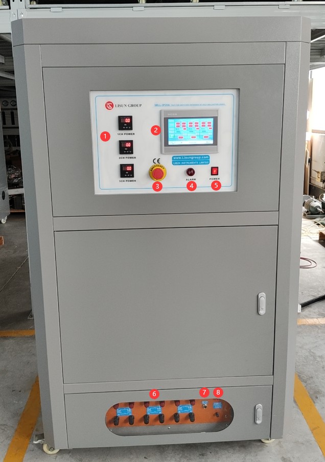
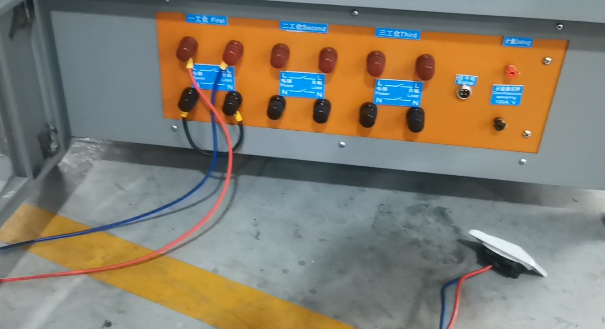
Equipment front panel. = 1 * GB3① Power meter; 3 power meters for 3 workstations; = 2 * GB3② Touchscreen; = 3 * GB3③ Emergency stop; = 4 * GB3④ Alarm; = 5 * GB3⑤ Power switch;= 6 * GB3⑥: 12 terminals in total for 3 workstations; for single-pole switches, short N to L and connect L to the switch; for double-pole switches, connect both L and N to the switch;= 7 × GB3⑦ Signal terminals: Output signals when an alarm is triggered at a corresponding workstation. Pin 1 corresponds to Workstation 1, Pin 2 to Workstation 2, Pin 3 to Workstation 3, and Pin 4 is the common terminal (output signal is a digital signal). These are used to send signals to the switch life tester to control workstation operation;= 8 * GB3⑧ Measurement terminal blocks, used to connect an oscilloscope for equipment measurement.
Note: If = 7 * GB3⑦ and = 8 * GB3⑧ are not connected, it does not affect the operation of the load cabinet’s testing functions.
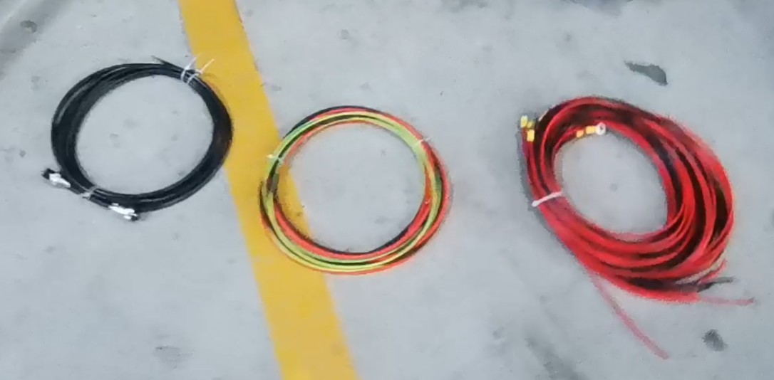
Accessories: Signal cable, power cable, ground cable, and workstation sample cable.
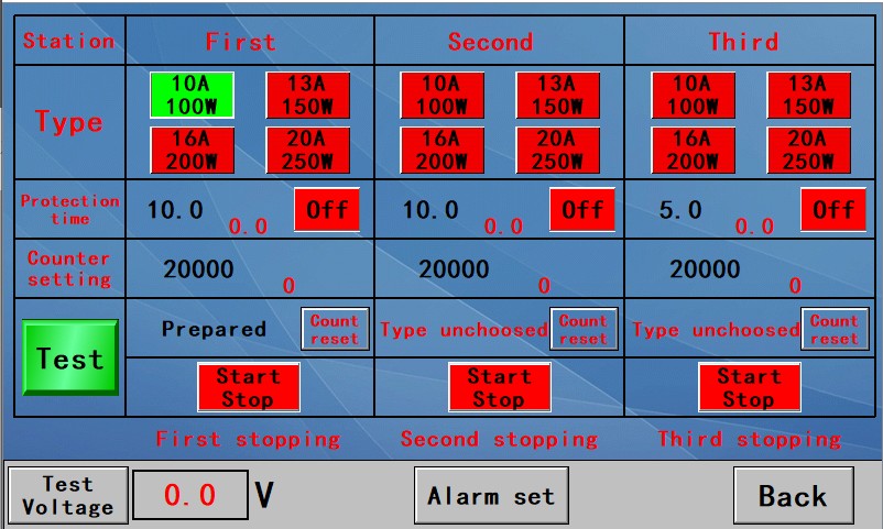
Touchscreen interface.
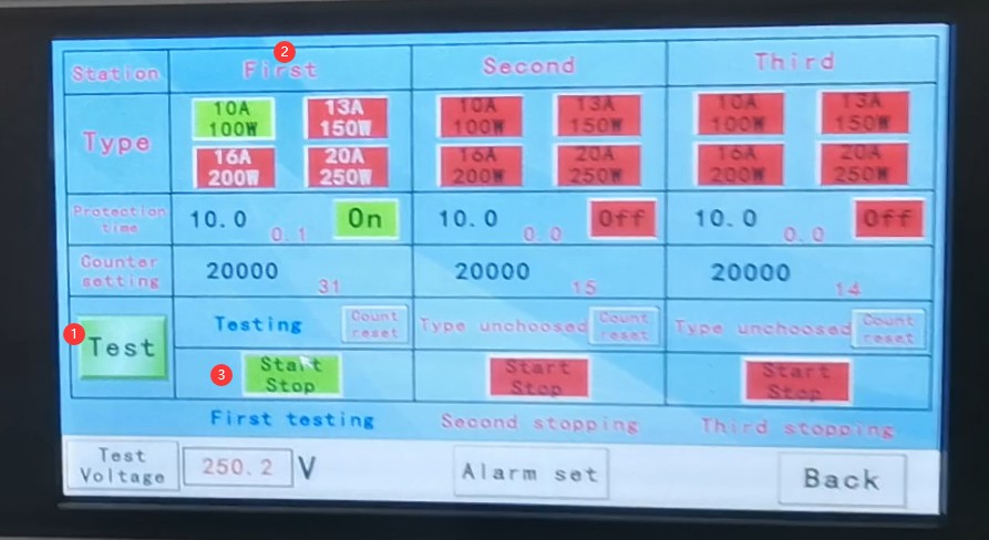
First row: Three-station display.
Second row: Test mode selection. Selected test modes are displayed in green; unselected test modes are displayed in red. To select a different mode for the same station, deselect the current mode and then select the desired mode.
Third row: Alarm delay time. When the device remains in the same state (closed or open) for the corresponding duration, an alarm will sound. When the device starts a test, this setting automatically changes from “Off” to “On” and begins timing; tap it manually to return it to the “Off” state.
Fourth row: Test pass/fail count.
Fifth row: When “Test” is displayed, the instrument is ready to perform normal testing. Click this button to switch the display to “Debug,” which enables metrological calibration of the device. Test start and end buttons.
Sixth row: Workstation status indicator.
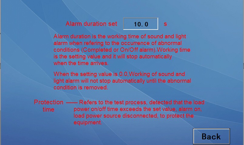
Seventh row: “Test Voltage”—tap to enter the test voltage settings interface. “Alarm Set”—tap to enter the alarm delay time settings.
Test Procedure
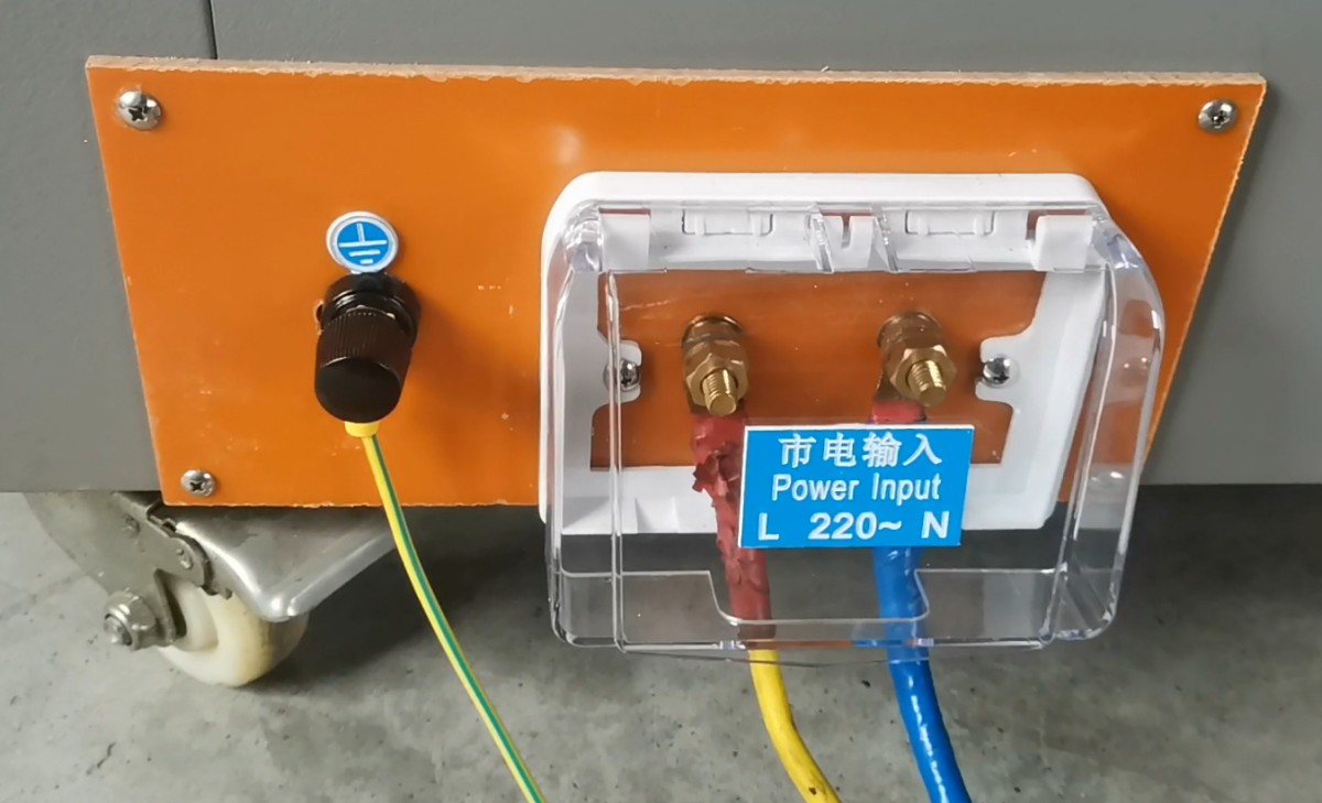
When connecting the device’s power cord, please verify that the input voltage is correct. When connecting the ground wire, please verify that the device is properly grounded.
For a three-station wiring setup, simply connect the wires to the number of stations required. Note: The figure below is for demonstration purposes only; in general, the wires should be connected to a switch life tester.
Turn on the device. Click “Alarm Set” and set the alarm delay time according to your needs.
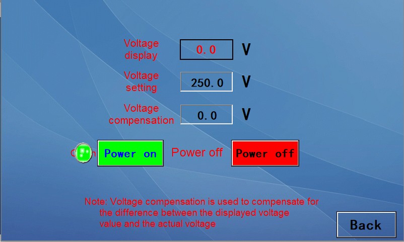
Click “Test Voltage” to set the test voltage to the desired value (250V), then click “POWER ON.” The displayed voltage will gradually adjust automatically to match the set voltage.
Note: “Voltage compensation” generally does not need to be set. If the final displayed voltage does not match the set voltage, please contact us.
= 1 * GB3① Verify that the device is in “Test” mode, = 2 * GB3② Select the desired test setting, = 3 * GB3③ Click to start the test.
When the continuous “on” or “off” state reaches the set alarm delay time, the device will trigger an alarm, and testing for that setting will automatically stop. Click “On” in the image below to reset the device.
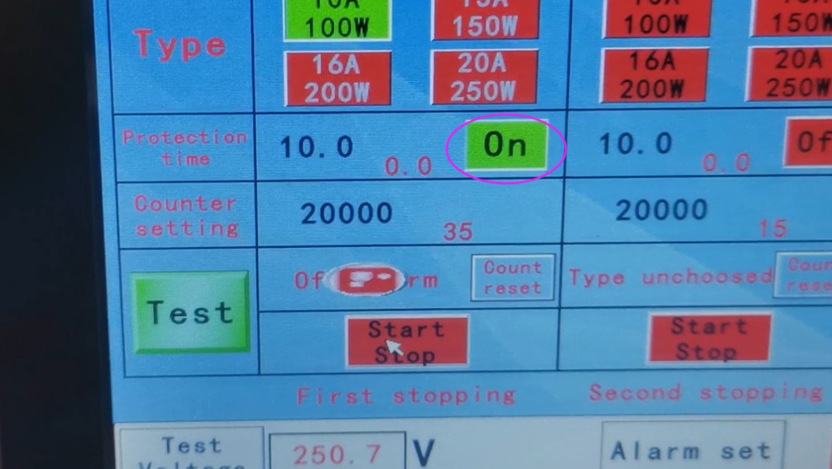
After the test is complete, click “Test Voltage,” then click “Power Off” to turn off the test voltage. Once the test voltage has automatically returned to 0, you may turn off the device’s power.
Debugging and Calibration Procedures
Note: Before adjusting any parameter, be sure to stop the test on the touchscreen first.
Connect the sample leads under normal test conditions.
Using a 1x probe, connect the oscilloscope as follows.
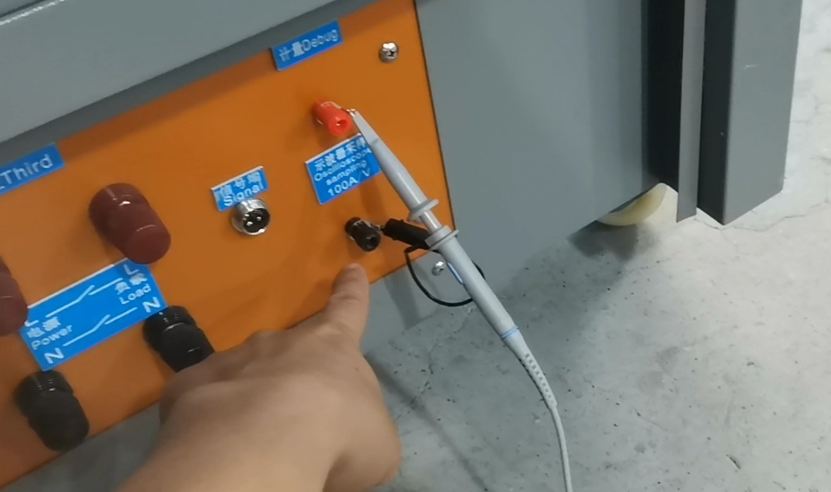
All settings are configured for normal test mode. Click “Test” to switch to “Debug” mode.
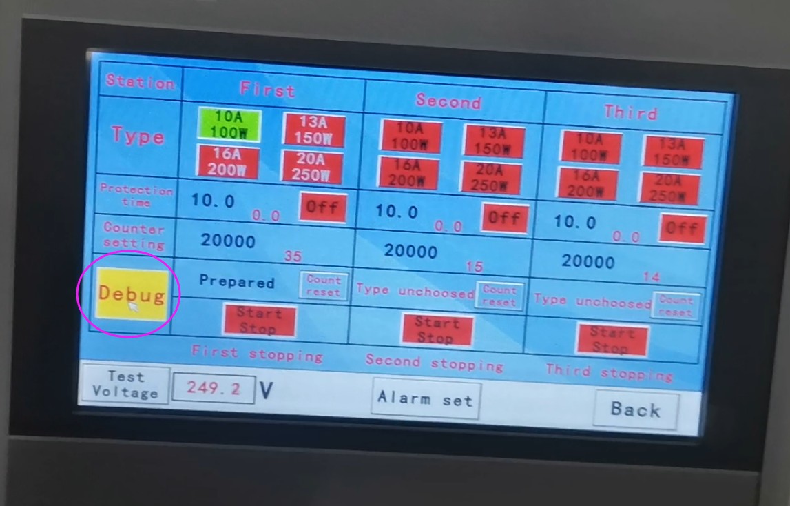
Using a single test station with a 10A test range as an example, click to start the test for the first test station.
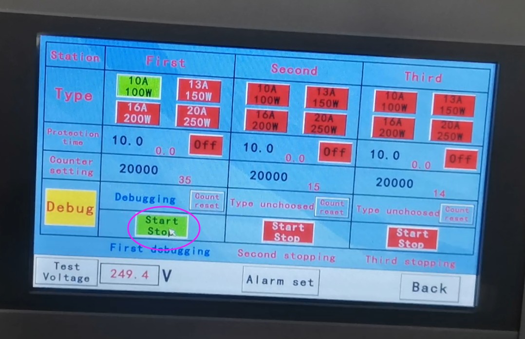
Keep the sample in this station in the closed position at all times. The equipment will automatically apply and remove the surge current for calibration.
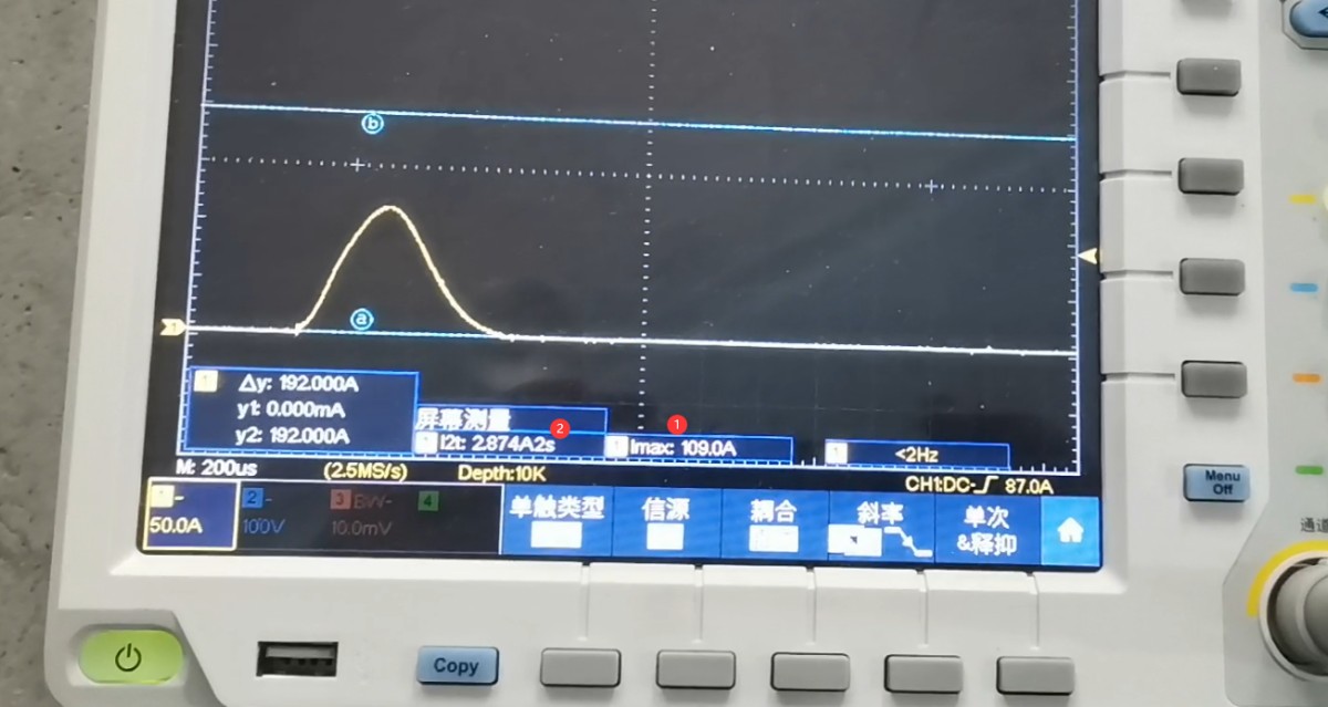
Oscilloscope settings: Trigger mode: Single; Probe multiplier: 1x (1X); Test current: Yes, 100 A/V. Capture the following waveforms and data: = 1 * GB3①Imax (standard value Ipeak is 108) and = 2 * GB3②I2t (standard value is 2.8), with a permissible error of ±5%.
Note: For data on other ranges, please also refer to Clause 19.3 of GB16915.1-2014 and Clause 19.3 of IEC60669-1:2017.
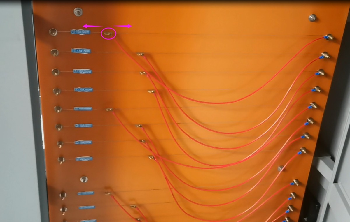
First, adjust the Ipeak surge current. As shown in the figure below, move the slider for the corresponding surge resistance setting to the left to decrease the surge resistance, which will increase the surge current. Conversely, move it to the right to increase the surge resistance, which will decrease the surge current.
After making the adjustments, use the oscilloscope to check the inrush current (Ipeak) again. If it is still incorrect, repeat the steps above.
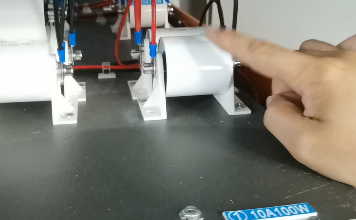
After adjusting Ipeak, proceed to calibrate I2t. As shown in the figure below, you may need to increase or decrease the corresponding capacitance. The capacitance is pre-calibrated at the factory and generally does not require adjustment. If changes are needed, please contact us.
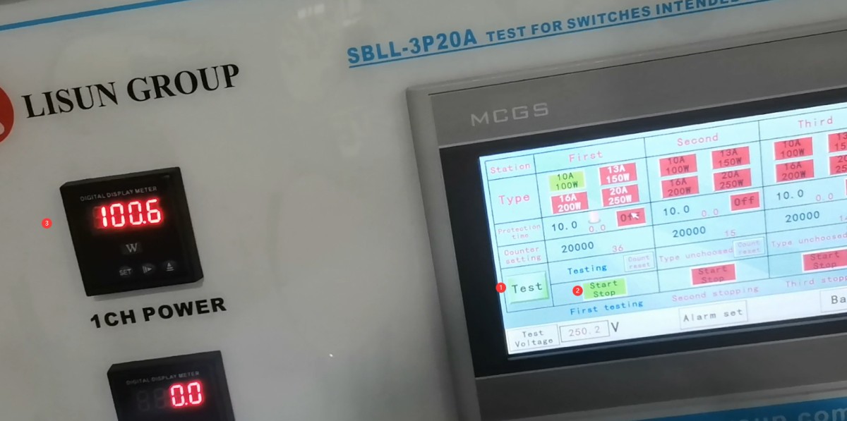
Calibrating the power resistor. = 1 * GB3① Set the device back to “Test” mode, = 2 * GB3② then click “Start Test,” = 3 * GB3③ Once the sample is closed, the corresponding power meter displays the power.
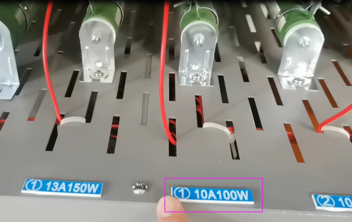
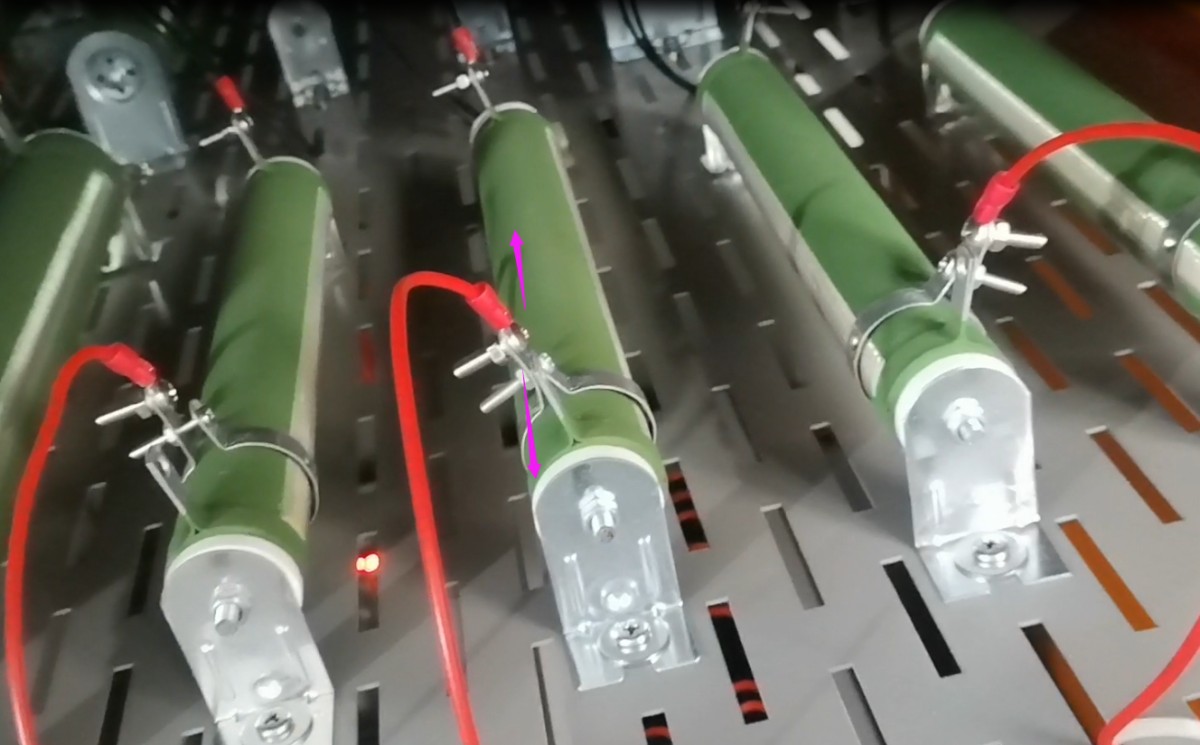
Locate the corresponding power resistor.
See the figure below. If the power is incorrect, loosen the clamp on the corresponding power resistor and slide it inward to reduce the resistance and increase the power; conversely, slide it outward to increase the resistance and decrease the power.
Photometric, Colorimetric, and Safety Performance Testing Solutions for LEDs
Goniophotometer System: LSG-6000, LSG-1890B, or LSG-1800ACCD
Spectroradiometer & Integrating Sphere Test System: LPCE-2 or LPCE-3
LED Life Maintains a Test System in Accordance with LM-84: LEDLM-84PL
Photobiological Radiation Safety Test System: EN 62471-C or EN 62471-P
Lamp Start, Run-up Time, and Flicker Test System: LSRF-3 and LSP-500VARC-Pst
LED Power Driver Testers: LS2090, M9822, and LSP-500VARC
IK Level Tester | Spring Hammer Impact Tester: IK07-10, IK01-06
Electrodynamic Vibration Generator System: LVD-100KG-6D
Electrical Safety Testers: LS9955, ZRS-3H, ZY-3, TTC-1
Environmental Chamber Test Solution for LED Luminaires
Waterproof Test for IPX5 and IPX6: JL-56
Dustproof Testing Machine for IP5X and IP6X: SC-015
High- and Low-Temperature and Humidity Chamber: GDJS-015B
Salt Spray Test Machine: YWX/Q-010
UV Lamp Aging Test Chamber: UV-263LS
Xenon Lamp Aging Test Chamber: XD-80LS
Ozone Test Chamber: OTC-150A
Sulfur Dioxide Test Chamber: SQ-010
EMC and EMI Test Solutions for CFL and LED Luminaires
EMI Test System: EMI-9KB or EMI-9KA
Electrostatic Discharge Simulator: ESD61000-2
EFT Immunity Measurement: EFT61000-4
Surge Generator: SG61000-5
Voltage Dips and Interruptions Generator: CSS61000-11
Ring Wave Generator: RWG61000-12

www. Lisungroup.com
Patents Filed
All rights reserved by Lisun Group
Subject to Change Without Notice