
 English
 中文简体
中文简体 English
 Русский
 Español
 Português
 Türkçe
 العربية
 Deutsch
 Polski
 Italiano
 Français
 한국어
한국어 ไทย
ไทย Tiếng Việt
 日本語
日本語





























Voltage Regulator
User's Manual
Applicable LISUN models: RTEU-SP10K、RTEU-SP15K、RTEU-SP1K、RTEU-SP20K、RTEU-SP5K、RTEU-TP10K、RTEU-TP15K、RTEU-TP20K、RTEU-TP6K、RTUS-SP10K、RTUS-SP15K、RTUS-SP1K、RTUS-SP20K、RTUS-SP5K、RTUS-TP10K、RTUS-TP15K、RTUS-TP20K、RTUS-TP6K
1. Basic Understanding of Equipment
1.1 Product Overview
1.1.1 Model Classification
| LISUN Model | Input Voltage | Output Voltage | Power |
|---|---|---|---|
| RTEU-SP1K | Single-phase / 198–264 V | 0–300 V (adjustable) | 1 kVA |
| RTEU-SP5K | Single-phase / 198–264 V | 0–300 V (adjustable) | 5 kVA |
| RTEU-SP10K | Single-phase / 198–264 V | 0–300 V (adjustable) | 10 kVA |
| RTEU-SP15K | Single-phase / 198–264 V | 0–300 V (adjustable) | 15 kVA |
| RTUS-SP1K | Single-phase/99–132 V | 0–300 V (adjustable) | 1 kVA |
| RTUS-SP5K | Single-phase/99–132 V | 0–300 V (adjustable) | 5 kVA |
| RTUS-SP10K | Single-phase / 99–132 V | 0–300 V (adjustable) | 10 kVA |
| RTUS-SP15K | Single-phase/99–132 V | 0–300 V (adjustable) | 15 kVA |
| RTEU-TP6K | Three-phase / 340–480 V | 0–500 V (adjustable) | 6 kVA |
| RTEU-TP10K | Three-phase / 340–480 V | 0–500 V (adjustable) | 10 kVA |
| RTEU-TP15K | Three-phase / 340–480 V | 0–500 V (adjustable) | 15 kVA |
| RTUS-TP6K | Three-phase / 198–264 V | 0–500 V (adjustable) | 6 kVA |
| RTUS-TP10K | Three-phase / 198–264 V | 0–500 V (adjustable) | 10 kVA |
| RTUS-TP15K | Three-phase / 198–264 V | 0–500 V (adjustable) | 15 kVA |
Formulas for calculating output current: Single-phase output current = rated power × 80% ÷ output voltage; three-phase output current = rated power × 80% ÷ 1.732 ÷ output voltage.
Note: 80% is the long-term load factor; the equipment must not be operated at full load for extended periods.
1.1.2 Product Applications
The RTEU series Voltage Regulators (also known as step-up/step-down adjustable Voltage Transformers) are AC voltage conversion devices, featuring a core wound around a toroidal iron core. With low power consumption and high conversion efficiency, it can convert grid voltages of various specifications into continuously adjustable output voltages, providing a stable and adjustable power supply for various electronic and electrical equipment as well as laboratory testing systems.
1.2 Operating Principle
1.2.1 Operating Principle of a Single-Phase Voltage Regulator
The single-phase Voltage Regulator features an adjustable voltage transformer design, with the coil uniformly wound around a toroidal core; the contact brushes are held tightly against the polished surface of the coil by spring pressure. Turning the adjustment knob on top causes the brush holder to slide along the surface of the coil, changing the contact position of the brushes on the coil and thereby altering the turn ratio on the output side, which enables smooth, stepless adjustment of the output voltage.
1.2.2 Operating Principle of A Three-Phase Voltage Regulator
The three-phase Voltage Regulator consists of three stacked single-phase voltage regulation units. The three brush holders are mounted coaxially, and the windings are connected in a star configuration. When the adjustment knob is turned, the three-phase brushes move synchronously, ensuring synchronous regulation and phase balance of the three-phase output voltage, thereby achieving continuous, synchronous adjustment of the three-phase output voltage.
1.3 Unboxing Inspection and Configuration Verification
1.3.1 Unpacking and Visual Inspection
When unpacking the device, handle it gently to avoid scratching the outer casing with sharp tools. After unpacking, first inspect the exterior of the device to ensure there is no visible deformation or dents, and that the buttons are not damaged or loose. If you notice any abnormalities with the device, please contact us immediately.
1.3.2 Downloading Electronic Documents
Download links for the digital user manual, warranty card, calibration certificate, and other documents have been sent via email. Please download them as soon as possible. If you missed the email, please feel free to contact us to request the download links again.
2. Safety Precautions
2.1 General Safety Guidelines
This equipment should only be wired and operated by personnel with basic knowledge of electrical work. Non-professionals should not disassemble or modify it without authorization.
Before use, be sure to verify that the local power grid voltage matches the device’s rated Input Voltage; connecting to the wrong voltage may cause permanent damage to the device.
High voltage is present inside the equipment while it is running. Do not open the chassis cover under any circumstances to prevent electric shock.
Do not place any objects on the device to avoid blocking the ventilation openings.
If the device emits an unusual odor, makes unusual noises, or emits smoke, immediately disconnect the input power supply, stop using the device, and contact customer service.
2.2 System Requirements
Indoor Use: This device is intended for use only in dry indoor environments. Do not place it outdoors or use it in environments where it may be exposed to rain or splashing water.
Temperature Requirements: The ambient temperature should be maintained between -10°C and 40°C. Avoid placing the device near heat sources or in direct sunlight.
Ventilation and Heat Dissipation: Maintain a ventilation clearance of at least 20 mm around the equipment. Do not cover the sides or top of the equipment—where heat is dissipated—with fabric, cardboard boxes, or other materials.
Placement Requirements: Place the unit on a flat, stable, hard surface to prevent tilting or vibration; do not place it on carpets, soft pads, or other surfaces that are flammable or that prevent heat dissipation.
Humidity and Dust: Avoid using in environments with high humidity, excessive dust, or corrosive gases.
2.3 Electrical Safety Standards
An air circuit breaker or fuse rated for the device’s input power must be installed on the input side to provide front-end protection.
Wiring must be secure and reliable; terminal connections should be tightened to prevent loose connections that could cause overheating or arcing.
The equipment must be reliably grounded, and the grounding resistance must comply with the requirements of national electrical safety standards.
The cross-sectional area of the input and output cables must meet the rated current requirements to prevent cable overload and overheating.
Before plugging in or unplugging the power supply or connecting any wires, you must ensure that the power source at the front end has been completely disconnected.
2.4 Safety Precautions During Operation
Do not exceed the rated power under any circumstances; the total load power must not exceed 80% of the equipment’s rated power. Prolonged operation at full load will accelerate equipment wear and tear and shorten its service life.
Never short-circuit the output terminals; doing so may cause serious damage to the equipment or even result in a fire.
Do not plug in or unplug load cables while the equipment is running; turn off the equipment or turn off the load switch first.
Do not allow foreign objects such as metal shavings, screws, or wire ends to fall inside the equipment, to prevent internal short circuits.
Before cleaning the equipment, you must unplug the input power supply cord or turn off the circuit breaker at the source; cleaning while the equipment is powered on is strictly prohibited.
3. Equipment Overview and Operation
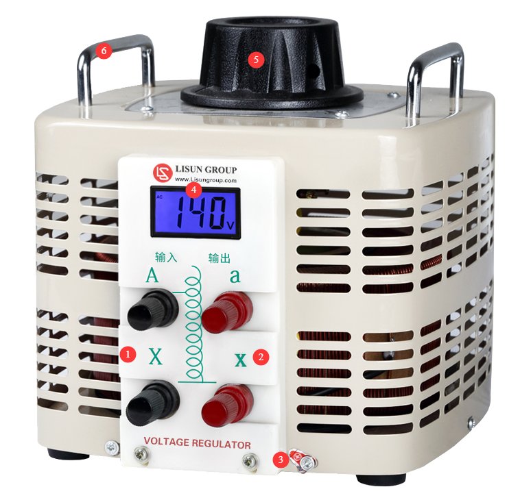
3.1 RTEU-SP Series
See Figure 3-1.
| Number | Note |
|---|---|
| ① | Input side (black terminals): A (input hot wire), X (input neutral wire) |
| ② | Output side (red terminals): a (output hot wire), x (output neutral wire) |
| ③ | Ground Terminal |
| ④ | Output Voltage Display |
| ⑤ | Output voltage adjustment knob with a built-in mechanical limit mechanism that restricts the output voltage adjustment range |
| ⑥ | Metal handles for easy transport and movement of the equipment |
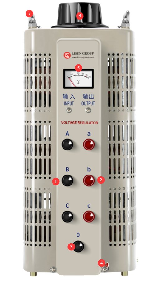
3.2 RTEU-TP Series
See Figure 3-2.
| Number | Note |
|---|---|
| ① | Input Side (Black Terminals): A, B, C (Three-phase live wire inputs) |
| ② | Output Side (Red Terminals): a, b, c (three-phase live wire outputs) |
| ③ | Input and Output Zero Line / Neutral Line Common Terminal |
| ④ | Ground Terminal |
| ⑤ | Dart-type voltmeter, displays the line voltage |
| ⑥ | Output voltage adjustment knob; coaxial control for synchronized adjustment of three-phase brushes; built-in limit mechanism |
| ⑦ | Metal handles for easy transport and movement of the equipment |
3.3 General Operating Procedures
| Procedure | Note |
|---|---|
| ① Verify Power Is Off | Turn off the input power supply, and use a multimeter to verify that there is no voltage at the input terminals. |
| ② Grounding Wire Connection | Make a secure connection between the equipment enclosure’s grounding terminal and the on-site protective grounding conductor. |
| ③ Input-Side Wiring | Connect the input power supply cord to the black terminal. For single-phase systems, pay attention to the live and neutral wires; for three-phase systems, pay attention to the phase sequence. |
| ④ Voltage Pre-adjustment | Turn on the power switch on the input side, turn the voltage adjustment knob, and adjust the output voltage to the desired level before connecting the load. |
| ⑤ No-load operation | When powering on the device for the first time or using it for the first time after a long period of storage, it is recommended to let it run idle for 3 minutes to check for any unusual noises, odors, or excessive heat. |
| ⑥ Confirm Power Is Off | After confirming that everything is operating normally during no-load operation, disconnect the input power supply again and use a multimeter to verify that there is no voltage at the input terminal. |
| ⑦ Output-Side Wiring | Output Wiring: Connect the output load power cord to the red terminal. For single-phase systems, pay attention to the live and neutral wires; for three-phase systems, pay attention to the phase sequence. The neutral terminal is shared by both the input and output. Ensure that the total load power does not exceed 80% of the Voltage Transformer’s rated capacity. |
| ⑧Normal Operation | Turn the input power switch back on; the Voltage Transformer will output power normally. Gradually turn on the load devices. It is recommended to turn on the lower-power loads first, followed by the higher-power loads. |
| ⑨ Operational Monitoring | Check again to see if the Voltage Transformer’s output voltage has changed; if necessary, fine-tune the voltage adjustment knob. |
| ⑩ Turn off the load | When it is necessary to shut down the system, first turn off the power switches for all load devices one by one. |
| ⑪ Shutdown | Finally, disconnect the input power supply. For safety, disconnect all input and output cables and turn the voltage adjustment knob counterclockwise to the lowest position. |
4. Routine Maintenance and Care
4.1 Routine Inspection Items
Conduct a quick visual inspection before and after each use, checking the following: whether the equipment housing is clean and free of water stains or foreign objects; whether the power cord is intact and free of damage or signs of aging; whether there are signs of overheating or discoloration at the terminal blocks; whether the ventilation and heat dissipation openings are blocked by dust or debris; whether the equipment is placed on a stable surface and shows no signs of tilting or shifting;
4.2 Items for Regular Inspection
It is recommended that a professional electrician perform a comprehensive maintenance check on a regular basis: Open the enclosure to inspect the condition of the internal windings, terminal blocks, and protective components; clean out accumulated dust inside, and check the insulation for signs of aging or cracking; test the DC resistance of the Voltage Transformer windings to determine if there are any turn-to-turn short circuits; verify that the operating thresholds of the overload protection devices are accurate; and tighten all internal terminal blocks and connecting bolts.
4.3 Long-Term Storage Requirements
Before storing the equipment for an extended period, it should be thoroughly cleaned and ensured to be dry and free of moisture.
The storage area should be well-ventilated, dry, and dust-free, and should be protected from high temperatures, high humidity, and corrosive gases.
The equipment should be stored in its original packaging or covered with a dust cover to prevent dust buildup.
During storage, power on the unit once every 3 months and let it run at no load for 30 minutes to remove internal moisture.
Before using the device again after a long period of storage, perform the checks and warm-up procedures as part of the initial startup process.
5. Troubleshooting and Resolving Common Problems
5.1 Faults Related to Abnormal Voltage Output
5.1.1 No voltage at the output
| Possible Causes | Troubleshooting Steps | Procedure |
|---|---|---|
| The input power supply is not connected | Check the status of the input-side power switch and fuses, and measure the voltage at the input terminals. | Turn on the power switch and replace the blown fuse. |
| Input Wiring Break / Loose Connection | After turning off the power, check the wiring at the input terminals and test the wires for continuity. | Retighten the terminals, and repair or replace any broken wires. |
| The brush has completely detached from the coil. | After the power is turned off, check the position of the brush holder and verify whether the handwheel has exceeded its travel range. | Return the knob to its normal travel range and check whether the brush holder has come loose. |
| Internal break in the coil | Check the coil for continuity after power is turned off | Contact the manufacturer to have the coil repaired or replaced |
5.1.2 The output voltage cannot be adjusted
| Possible Causes | Troubleshooting Steps | Procedure |
|---|---|---|
| Adjustment Handwheel Sticking or Stripped Threads | Try turning the handwheel to check if it is jammed by a foreign object or if any of the mounting screws are loose. | Remove any foreign objects causing a jam; do not force the unit to turn with excessive force, and tighten the screws securely. |
| Detachment of the Brush Frame Drive Mechanism | After turning off the power, open the cover and inspect the connection between the handwheel and the brush holder. | Reassemble the drive assembly and tighten the fasteners. |
| The brush is stuck against the coil | Check the brushes for cracks, uneven wear, or jamming. | Replace damaged brushes and adjust the brush holder position |
5.1.3 Significant Output Voltage Fluctuations
| Possible Causes | Troubleshooting Steps | Procedure |
|---|---|---|
| Fluctuations in the input power supply itself | Measure the voltage on the input side to verify the stability of the power grid. | Use a stable input power supply, or install a voltage regulator at the front end. |
| Poor brush contact | With the power off, check the brush surfaces and coil contact surfaces for oxidation or stains. | Clean the coil contact surfaces; sand or replace the brushes |
| Loose Terminal Blocks | Check the input and output terminals for looseness or overheating. | Tighten all terminal connections |
| Severe fluctuations in load | Determine whether the load starts and stops frequently or undergoes significant fluctuations | Stabilize the load, or replace the equipment with a higher-capacity model |
5.1.4 The output voltage does not reach the rated maximum value
| Possible Causes | Troubleshooting Steps | Procedure |
|---|---|---|
| Input Voltage is too low | Measure the input power supply voltage to verify whether it is below the lower limit of the rated input. | Raise Input Voltage to within the permissible range |
| Overload | Measure the no-load voltage after disconnecting the load to determine whether the voltage drop under load is excessive. | Reduce the load, or replace the equipment with a higher-capacity model |
| Severe brush wear and poor contact | Check the brushes for wear and ensure they make a tight contact. | Replace the brushes and adjust the spring tension |
| Local Short Circuit in the Coil | Test the coil’s resistance and insulation properties, and check for any burning smell. | Shut down the machine immediately and contact the manufacturer for repairs. |
5.2 Operational Anomalies
5.2.1 Unusual Noises During Equipment Operation
| Possible Causes | Troubleshooting Steps | Procedure |
|---|---|---|
| Electromagnetic Noise from the Iron Core | With the load disconnected, listen for the sound to determine its location and assess whether it is a uniform electromagnetic sound from the core. | A faint, steady electromagnetic hum is normal; if there is a noticeable abnormal noise, turn off the power and tighten the iron core assembly. |
| Noise Caused by Brush Friction | Listen to determine if the sound is caused by friction between the brush and the coil. | Clean the surface of the coil, check whether the brushes are worn unevenly, and adjust the brush pressure. |
| Loose internal parts | Turn off the power and shake the equipment to listen for any rattling sounds caused by loose parts. | Open the cover to inspect and tighten any loose parts |
5.2.2 Excessive Temperature Rise in Equipment
| Possible Causes | Troubleshooting Steps | Procedure |
|---|---|---|
| Long-term Overload Operation | Measure the output current to verify whether the load power exceeds the rated value. | Reduce the load; operate at a derated capacity |
| Clogged ventilation openings, poor ventilation | Check whether the ventilation openings are blocked by dust or foreign objects, and ensure there is adequate space around the device for heat dissipation. | Clean the ventilation openings and ensure there is sufficient space for heat dissipation. |
| Heat Generated by Poor Terminal Contact | Check the terminals for discoloration or overheating. | Disconnect the power supply, tighten the terminals, and polish the oxidized contact surfaces. |
| Local Short Circuit in the Coil | Check the coil’s resistance and insulation, and check for any burning smell. | Shut down the machine immediately and contact the manufacturer for repairs. |
5.2.3 Sparks at the Brushes
| Possible Causes | Troubleshooting Steps | Procedure |
|---|---|---|
| Insufficient brush pressure, poor contact | With the power off, check the spring tension of the brushes and ensure they are making a tight contact. | Adjust the spring tension to ensure the brushes make even contact with the coil. |
| Oxidation and stains on the coil surface | Check the coil contact surfaces for oxidation, dust, or oil residue. | Wipe the coil contact surfaces with clean, anhydrous ethanol, and let them air dry before use. |
| Severe wear and cracking of the brushes | Inspect the appearance and wear of the brushes | Replace with brushes of the same specifications |
| Excessive load, current exceeds limit | Check whether the output current exceeds the limit | Reduce the load current to within the rated range |
5.2.4 Display / Abnormal Header Indication
| Possible Causes | Troubleshooting Steps | Procedure |
|---|---|---|
| The digital display shows nothing | Check whether the input power supply is normal and see if the power supply cables are loose. | Connect to a normal power source; the maintenance display indicates the power supply line. |
| The pointer is stuck, and the reading is inaccurate. | Check whether the pointer is stuck, and use a multimeter to measure the output voltage for comparison. | If the hand is slightly stuck, gently tap the dial to reset it; if the time is inaccurate, calibrate or replace the movement. |
| Significant Deviation in Displayed Values | Measure the output voltage with a high-precision multimeter and compare it to the displayed value. | If the deviation exceeds the tolerance, contact the manufacturer to have the voltmeter calibrated. |